Sungrow SBR Series User guide

GD_202111_Sungrow SBR HV Battery Installation Quick Guide with SHRT _V3.0
Page 1 of 6
© Sungrow Australia Group Pty. Ltd. All rights reserved.
As we continuously improving our services, changes to this document may occur without notice.
Sungrow SBR HV Battery Installation Quick Guide - SHRT series
Sungrow has released high-voltage battery - SBR series (9.6kWh-25.6kWh).
To ensure smooth installation and avoid difficulty on site, please read below checklists and make
sure you are ready before installing SBR HV batteries. If you have any questions, please free to
asking help onsite to reduce urgency.
Check Items
Requirements
Confirm?
Manuals
•Read Sungrow product manuals before the installation.
•Follow the manuals and make sure the operating environment
is suitable for inverter and batteries.
Application
•Check with the distributors or Sungrow team for technical advice
of off-grid application or any other complex scenarios (click here)
•Battery parallel application will not be available until Q3 2021 and
the exact date is to be informed by Sungrow.
Remote
Support
•If it is the first installation of HV battery system, Sungrow advises
installers to book the time for remote support. Our team will
deliver support when you are on site to avoid any difficult to
reachus.
Remote Area
•Installers need to be cautious for the remote installation.
•Installer must take responsibility of the after-sales service.
•Sungrow technical support will be limited if the battery systems
are installed remote areas with no local electrician for service
(click here for remote area policy)
Internet
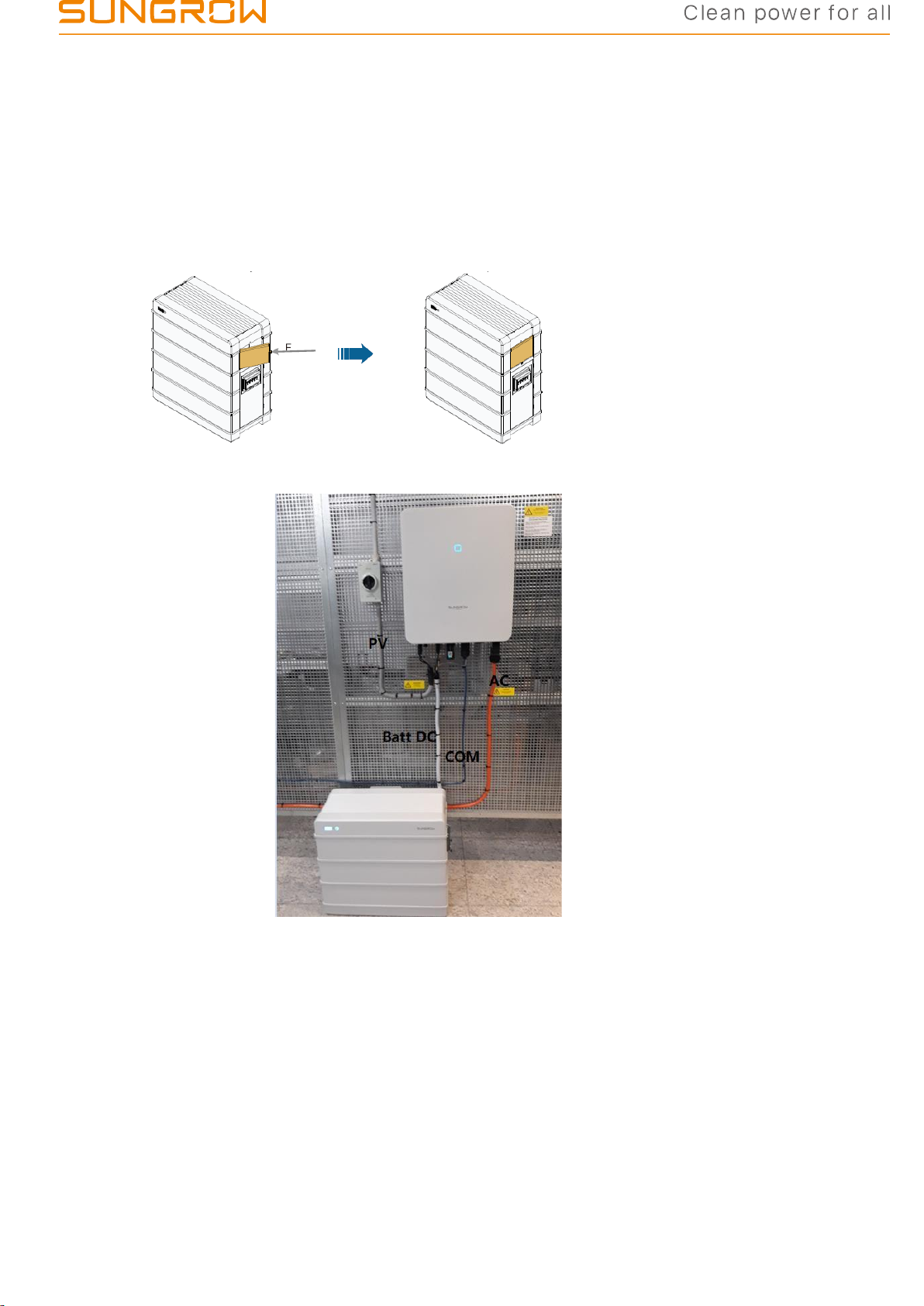
•The system needs to operate with Internet available. otherwise,
Sungrow’s support will be limited and less efficient.
•If there is no Internet connection, please contact the distributors
to purchase 4G dongle for internet access.
Cables/Tools
Prepare tools and cables prior to the installation.
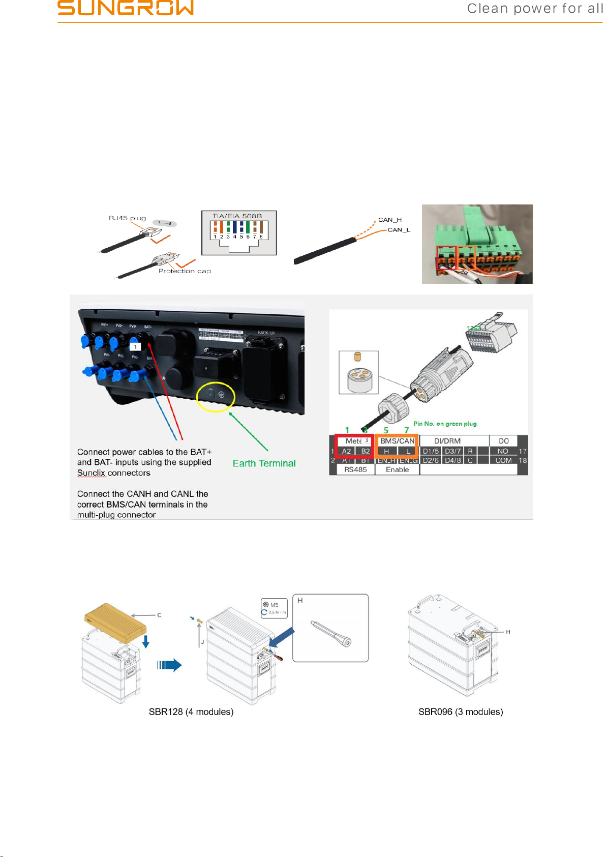
•DC power cables≥11AWG (DCmax=30A, 6mm2recommended)
with the insulation compliant to Australia Standard.
•Earth cables ≥13AWG (4mm2recommended)
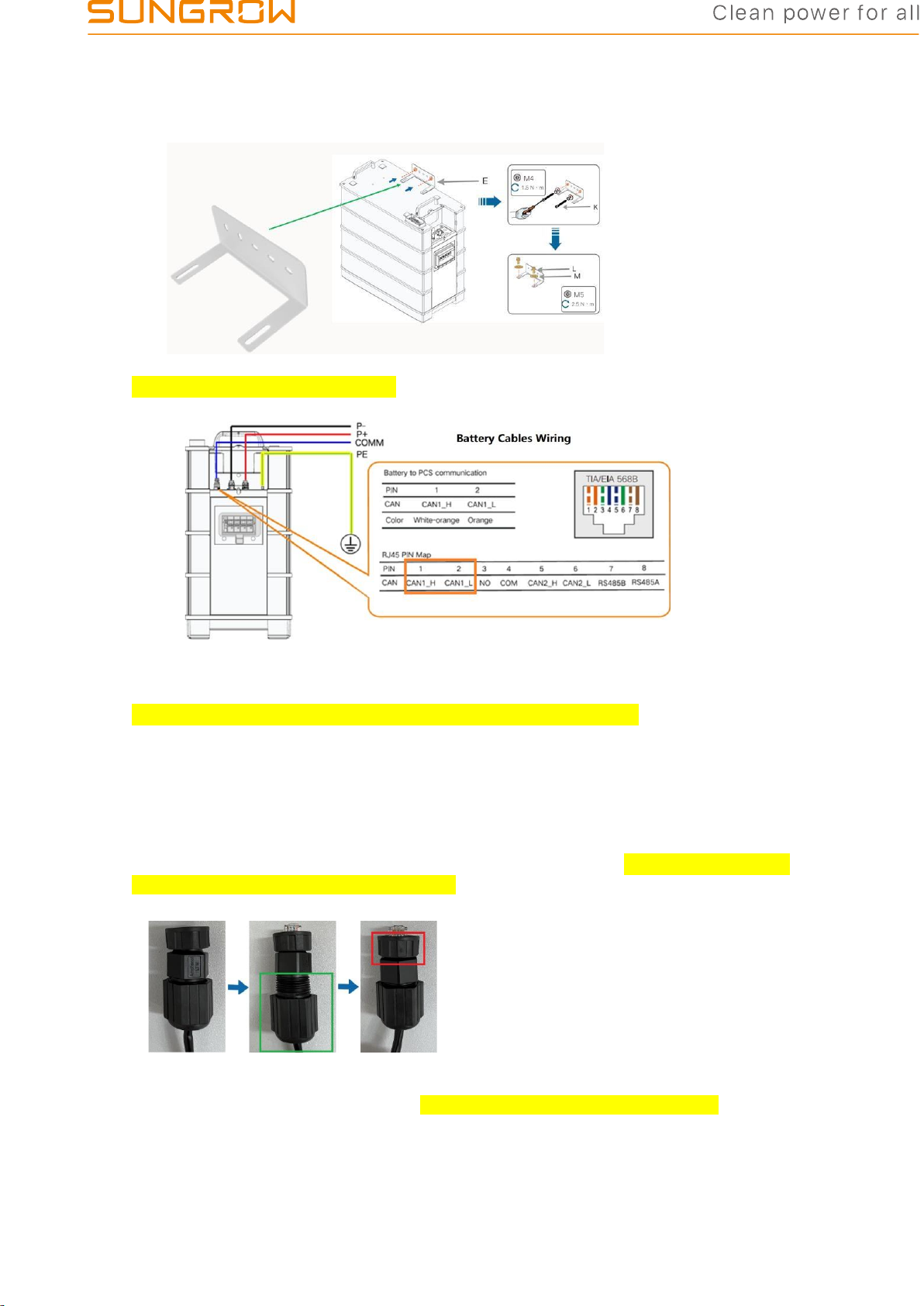
•Tools to make Ethernet cable with RJ45 terminal.
•The latest version of iSolarCloud is necessary to be installed on
mobile or tablet prior to the commissioning and firmware
upgrading.
Comm. Cable
•Long cables (>10 m) could cause communication failure
between the inverter and battery.
•It’s installer’s responsibility to conduct communication
cable continuity test before contacting Sungrow team
Tips
•Follow the installation tips & commissioning tips from the 2nd
page of this document

GD_202111_Sungrow SBR HV Battery Installation Quick Guide with SHRT _V3.0
Page 2 of 6
© Sungrow Australia Group Pty. Ltd. All rights reserved.
As we continuously improving our services, changes to this document may occur without notice.
Sungrow SBR HV Battery Installation Tips
Installation requirements:
Sungrow recommends that the shaded side of the building would be better toprevent
the battery from exposure to the sun, rain, and snow. Battery must not be mounted
in direct sunlight as this affects the internal heat, and therefore efficiency of the
battery and warranty.
Minimum clearances:

GD_202111_Sungrow SBR HV Battery Installation Quick Guide with SHRT _V3.0
Page 3 of 6
© Sungrow Australia Group Pty. Ltd. All rights reserved.
As we continuously improving our services, changes to this document may occur without notice.
Installation process - SBR128 (4 modules) as an example
1.
Screw feet in (Optional and to be available in Q4 2021).
2.
Place the base at the acceptable position in right way (arrows outward).
3.
Stack up battery modules.
4.
Insert BMU (make sure the DC MCB is off) and screw in.

GD_202111_Sungrow SBR HV Battery Installation Quick Guide with SHRT _V3.0
Page 4 of 6
© Sungrow Australia Group Pty. Ltd. All rights reserved.
As we continuously improving our services, changes to this document may occur without notice.
5.
Apply L-bracket to fix the battery to the wall.
6.
Cable’s plug-in and wiring
6-1. DC cables
Two DC cables (6mm2) need to be prepared by installers with Sunclix connectors.
One cable must have the same type of terminals at both ends to make sure
positive-to-positive & negative-to-negative connection.
6-2. Earthing
Green & Yellow earth cable (4mm2) needs to be prepared by installers.
6-3. COMM cable (Example of Sungrow COMM cable)
Sungrow provides battery COMM cable with 568B type, using White-Orange
cable for CAN_H, Orange cable for CAN_L
COMM Connection on battery side
Twist and loosen the green part and push the cable out as much as possible. Then fix
the green part.
Twist and loosen the red part, plug the terminal into battery COMM port and then screw
in to make sure the cable cannot be pulled out.

GD_202111_Sungrow SBR HV Battery Installation Quick Guide with SHRT _V3.0
Page 5 of 6
© Sungrow Australia Group Pty. Ltd. All rights reserved.
As we continuously improving our services, changes to this document may occur without notice.
COMM connection on inverter side
Standard cable provided by Sungrow connected to COM 2 (green plug)
–
Pin 1&3 are for smart meters
–
Pin 5&7 are for battery’s CAN connection
7.
Put on the lid and fix it with the Stud ‘H’.
Note: Directly use the Stud ‘H’ fix the lid, breaker module and the battery if the battery is
SBR096 (3 modules).

GD_202111_Sungrow SBR HV Battery Installation Quick Guide with SHRT _V3.0
Page 6 of 6
© Sungrow Australia Group Pty. Ltd. All rights reserved.
As we continuously improving our services, changes to this document may occur without notice.
8.
Put on the front cover
–
The battery with 3 modules (SBR096) does not need the cover.
–
The battery with 4 modules (SBR128) needs 1 front cover;
–
The battery with 5 modules (SBR160) needs 2 front covers;
⋮
–
The battery with 8 modules (SBR256) needs 5 front covers;
9.
A completed installation is shown below.

GD_202111_Sungrow SBR HV Battery Installation Quick Guide with SHRT _V3.0
Page 7 of 6
© Sungrow Australia Group Pty. Ltd. All rights reserved.
As we continuously improving our services, changes to this document may occur without notice.
Sungrow SBR HV Battery Commissioning Tips
Procedures
Details
1. Create the plant
on iSolarCloud
•Complete the WiFi configuration and put the system online (clickhere).
•Complete the system settings and grid settings.
•If the system keeps ‘under commissioning’ for more than 15min,
please contact Sungrow service team.
2. Battery Inspection
•Make sure the battery is fixed to the wall and notshakable.
•Make sure 4 cables (mentioned above) are correctlyconnected.
•Turn on the battery’s circuit breaker to check if the indicator is on.
3. Communication
check via local
access
Using iSolarcloud to get into local access with the following account and
password and then see the system diagram (click here).
Account: admin
Password: pw8888
•Wait for the compulsory firmware upgrade if there is.
•Tap the battery icon to see if the key parameters are observable –e.g.
voltage, SOC, SOH and etc.
4. Battery Settings
via local access
•Go to ‘More’- ‘Setting’ – ‘System Parameters’ to check the system
information.
•Go to ‘More’- ‘Setting’ – ‘Battery Parameters’ to set SOC upper and
lower limit if needed (5%-100%by default).
•Go to ‘More’- ‘Setting’ – ‘Energy Management Parameters’ to set
charge/ discharge time if needed.
•Go to ‘More’- ‘Setting’ – ‘Operation Parameters’ - ‘Off-grid
Parameters’ to turn on ‘Backup Mode’ if needed.
5. Quick test
(optional)
•Usually if the power flow is visible in the local access, the system
should operate normally.
•If no power flow in/out from battery side, optionally you may follow
the Step 3 & 4 –Go to ‘More’- ‘Setting’ – ‘Energy Management
Parameters’ – General –Change ‘Self-consumption mode’ into
‘Compulsory mode’–set charge/discharge power 1-3 kW
•Back to homepage to see if the power flow in/out the battery.
6. Other issue
•If there is the communication problem, please firstly check the COM
connection between battery and inverter.
•Regarding to the issue at inverter side, please firstly do thefirmware
upgrade (locally) or contact Sungrow service team’s help.
This manual suits for next models
1
Table of contents
Other Sungrow Batteries Pack manuals