manuals.online logo
Brands
  1. Home
  2. •
  3. Brands
  4. •
  5. ASL INTERCOM
  6. •
  7. Batteries Pack
  8. •
  9. ASL INTERCOM BPC65 User manual

ASL INTERCOM BPC65 User manual

Installation Guide
ASL Document Ref.: U-0456-0142.doc
Issue: 03 complete, approved - Date: 25/10/11
Part Number: M0456_67
BPC65 / BDIST / MDIST
Battery Pack, Charger, Battery and Mains Distribution
BATTERY TRAY
(for rack with 800 mm depth)
CHARGER
AND
BATTERY DISTRIBUTION TRAY
BPC65 / BDIST / MDIST – Installation Guide
Copyright © 2011 Application Solutions (Safety and Security) Limited
Application Solutions (Safety and Security) Limited
Unit 17 Cliffe Industrial Estate
Lewes - East Sussex
BN8 6JL - UK
Tel: +44(0)1273 405411 Fax: +44(0)1273 405415
www.asl-control.co.uk
All rights reserved.
Information contained in this document is believed to be accurate, however no representation or warranty is given and Application
Solutions (Safety and Security) Limited assumes no liability with respect to the accuracy of such information.
U-0456-0142.doc – Issue: 03 complete, approved
Page 2 of 20
This equipment is designed and manufactured to conform to the following EC standards:
EMC: EN 61000-6-4:2007, EN 61000-6-2:2005, EN 50121-4:2006, EN 61000-4-13:2002,
ENV 50204:1995, EN 50130-4:1996
Safety: EN 60950-1:2006 (pollution degree 2)
Voice Alarm: When installed in a Voice Alarm system designed in accordance with the
ASL EN 54-16 & ISO 7240-16 System Design Guide (T-0667-0016) and configured as
described in its user documentation, this equipment meets the requirement of
EN 54-16:2008, ISO 7240-16:2007, BS 5839-8:2008, EN 54-4:1997, EN 54-4:1997/A1:2002
and EN 54-4:1997/A2:2006.
Failure to use the equipment in the manner described in the product literature will invalidate the
warranty.
A ‘Declaration of Conformity’ statement to the above standards, and a list of auxiliary equipment used
for compliance verification, is available on request.
This product must be disposed of in accordance with the WEEE directive.
Contents
1General Information ................................................................................................................................................... 3
2Installation ................................................................................................................................................................. 5
3Mechanical Dimensions............................................................................................................................................ 14
4Safety and Precautions............................................................................................................................................. 17
Additional User Documentation:
1. BPC65 Product Manual (U-0456-0143)
2. ASL EN 54-16 & ISO 7240-16 System Design Guide (T-0667-0016)
3. Above documentation and additional reference information are available from the ASL’s website at
www.asl-control.co.uk
BPC65 / BDIST / MDIST – Installation Guide
U-0456-0142.doc – Issue: 03 complete, approved
Page 3 of 20
1 General Information
Technical Specification Summary
BPC65
AC Supply Voltage.........................................................................................................................230 V ±10% RMS 50Hz AC
In-rush Current (worst case) ......................................................................................................................................... 40 A
Maximum AC VA Rating (110 V).................................................................................................................................. 253 VA
AC Supply Fuse Rating............................................................................................................................... T3.15A IEC60127
Output Voltage .............................................................................................................................................. 27.3 V (@ 20°C)
Charger Output Fuse Rating ...................................................................................................... 7.5 A (mini blade type fuse)
Lowest voltage to which the battery can be discharged .................................................................................................21 V
Rated Continuous Maximum Output Current (Imax. a) ................................................................................................... 1.75 A
Rated Maximum Output Current (Imax. b) ........................................................................................................................... 5 A
Minimum Loading of the Equipment (Imin) ................................................................................................................... 50 mA
Maximum value of internal battery resistance
for which rack functionality can be maintained (Ri max)..................................................................................................0.1 Ω
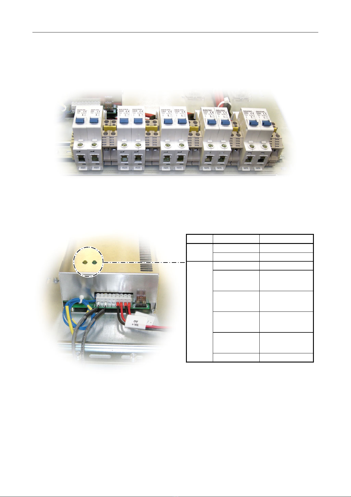
Charger Output Current.................................................................................................... 3 A / Type C Mini Circuit Breaker
Battery Output Current ................................................................................................... 25 A / Type C Mini Circuit Breaker
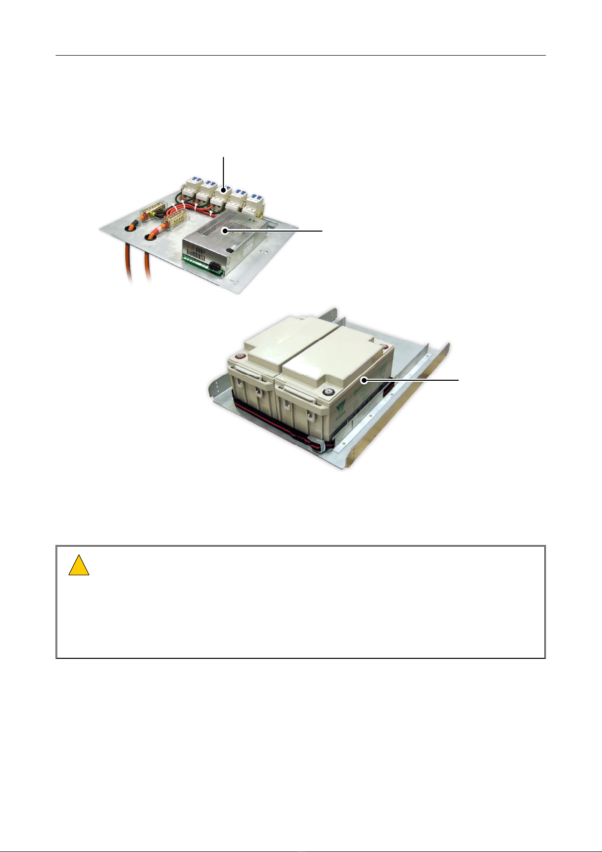
Batteries ....................................................................................................................................2 x Yuasa NPL65-12 (VLRA)
Charging Time..............................................................................................................24 hours to charge to 100% capacity
Temperature Compensation......................................................................................................................... –36 mV/cell/°C
Fault Status Output (Pins 1 and 3)........................................................................... volt-free relay contacts (N/O and COM)
Overall Dimensions (H x W x D) / Weight:
Charger and BDIST Tray.......................................................................................... 80 mm x 450 mm x 385 mm / 5.5 kg
Battery Tray with Batteries (for 800 mm deep rack) ........................................... 176 mm x 476 mm x 660 mm / 55.4 kg
Battery Tray with Batteries (for 600 mm deep rack) ........................................... 176 mm x 476 mm x 460 mm / 51.6 kg
Battery (Yuasa NPL65-12) ...................................................................................... 174 mm x 350 mm x 166 mm / 23 kg
MDIST
Operating Voltage ........................................................................................................................230 V ±10% RMS 50 Hz AC
Input Current ..........................................................................................................................................................32 A max
Output Current (per output)....................................................................................................................................10 A max
General
Temperature ............................................ −20°C to +50°C (storage, fully charged condition) / −10°C to +50°C (operation)
(battery performance is dependent on average operational temperature;
refer to manufacturer’s literature)
Humidity Range.......................................................................................................................... 0% to 93% non-condensing
!
!
At the time of the publication of this Installation Guide, only the BPC65 battery system for Schroff
800 mm Eurorack is EN54-16 and EN 54-4:1997+A1:2002+A2:2006 certified. Please refer to ASL for
further details.
BPC65 / BDIST / MDIST – Installation Guide
U-0456-0142.doc – Issue: 03 complete, approved
Page 4 of 20
Indicators and Controls
Figure 1 BDIST Mini Circuit Breakers
(REAR OF RACK)
BDIST
BDIST: The battery outputs are connected/disconnected to/from the systems by Miniature Circuit Breakers
(MCB) provided with the BDIST at the rear of the charger tray.
Figure 2 Charger indicators
CHARGER
(REAR OF RACK)
LED Status Indication
ON Mains is present
Power
(green) OFF Mains not present
OFF No fault
Single flash
repeated at
regular interval
Mains or charger fail
Two flashes
repeated at
regular interval
Incorrect output
voltage
Three flashes
repeated at
regular interval
High battery
resistance fault
Four flashes
repeated at
regular interval
Battery missing or
reverse battery
Fault
(yellow)
Continuously ON Microprocessor fail
BPC65 / BDIST / MDIST – Installation Guide
U-0456-0142.doc – Issue: 03 complete, approved
Page 5 of 20
2 Installation
2.1 Equipment and Tool Requirements
• BPC65 charger tray, battery tray, battery pack and front panels
• BDIST cable assembly of suitable size for all rack battery power feeds
• MDIST of suitable size for all rack mains feeds
• Flat-bladed screwdriver (small and medium)
• Pozidriv screwdrivers (1, 2 and 3)
• Wire cutters and strippers
• Ferrules and crimping tool
• AF spanner with insulated handle for 6 mm nuts
• AF spanner for 4 mm nuts
• A 19-inch standard rack fitted with supporting rails and wired with power supply, signal, and control
wiring, as required by your specific system design
2.2 Cabling Requirements
Signals Cable Description Termination Suggested Type
Mains supply 1 x 3-core mains
cable Suitable ferrules Suitably rated standard
mains cable
Mains distribution IEC-IEC 10 A
mains lead
• Amplifier Mainframe end:
IEC320-C13 (female)
• MDIST end: IEC320-C14 (male)
ASL MDIST4, MDIST6 or
MDIST8 cable assembly
Battery distribution
(for high current
equipment, e.g.
Amplifier Mainframes)
1 x 1-core red
1 x 1-core black
• Amplifier Mainframe end: 7W2
mixed signal D connector
(female)
• BPC65 end: suitable ferrules
ASL BDIST4-CA,
BDIST6-CA or
BDIST8-CA cable
assembly
Battery distribution (for
low current equipment,
e.g. Routers)
1 x 2-core cable
• VAR4/12/20 end: 2-way
pluggable Wago cage clamp
terminal (male)
• VAR8/VAR8-ACU end: suitable
ferrules
• BPC65 end: suitable ferrules
Suitably rated 2-core
cable
Fault relay 1 x 2-core cable
• VAR4/12/20 end: standard
25-way D connector (male)
• VAR8/VAR8-ACU end: suitable
ferrules
• BPC65 end: suitable ferrules
Suitably rated 2-core
cable

Refer to BS7671:2008 (Requirements for Electrical Installations) or other appropriate local standards
for guidelines on maximum potential cable lengths given the actual installation parameters.
BPC65 / BDIST / MDIST – Installation Guide
U-0456-0142.doc – Issue: 03 complete, approved
Page 6 of 20
2.3 Main Components
Figure 3 BPC65 components (rack with 800 mm depth as example)
CHARGER AND BDIST TRAY
BATTERY TRAY
(for rack with 800 mm depth)
BATTERIES
CHARGER
BDIST
2.4 Recommended Installation Procedure
!
!
1) Please read and observe the instructions and guidelines in Section “4 Safety and Precautions”
(page 17) prior to installation. Failure to follow these instructions and guidelines may cause
personal injury and/or damage to the equipment.
2) Use suitable ferrules for all terminal block connections.
3) This equipment is intended for use in a restricted access location.
4) To prevent injury, the battery backup system must be securely attached to the rack in accordance
with these installation instructions.
BPC65 / BDIST / MDIST – Installation Guide
U-0456-0142.doc – Issue: 03 complete, approved
Page 7 of 20
2.4.1 Battery Backup System Installation
!
!
1) Ensure that all safety precautions detailed in Section “Safety and Precautions” (page 17) are taken.
2) Note the correct polarity when connecting the interlink cable(s):
Red band terminal=Positive and Black band terminal=Negative.
3) For all cable connections use the terminal screws supplied with the batteries and ensure that they
are sufficiently tight.
2.4.1.1 Installing the Battery Tray and Batteries
1. Fit the battery tray to the rack in appropriate position securing it with twelve M6 screws;
see Figure 4.
Figure 4 Installing the battery tray
(Battery tray model varies
to suit the rack type)
3 x M6 POZIDRIV SCREW
3 x M6 WASHER
3 x M6 CAGE NUT
FRONT OF RACK
!
!Ensure that:
1) Three M6 cage nuts and screws are used in
each corner of the tray and that they are
tightly fitted.
2) One (minimum) earthing washer must be
used to ensure that the battery tray is
bonded to the rack.
BPC65 / BDIST / MDIST – Installation Guide
U-0456-0142.doc – Issue: 03 complete, approved
Page 8 of 20
2. Slide the batteries into the tray and then connect the interlink cable noting the layout diagram in
Figure 5.
Figure 5 Fitting the batteries into the tray
12V
FRONT OF
RACK
+
+
-
(Battery tray for rack with
800 mm depth as example)
12V
-
Always use insulated tools!
!
!
Fit protective cap to battery
terminals!
(Depending on the model supplied,
the battery terminal protective caps
must be fitted to the lead before its
connection to the battery terminal.)
!
!
Batteries are heavy (23 kg each).
Please move and handle with care to
avoid personal injuries and/or
damages to the batteries.
!
!
Note the correct polarity when
connecting the interlink cable:
Red band terminal=positive
Black band terminal=negative
!
!
3. Fit a protective cap (supplied) to each of the battery terminals connected to the interlink cable.
BPC65 / BDIST / MDIST – Installation Guide
U-0456-0142.doc – Issue: 03 complete, approved
Page 9 of 20
2.4.1.2 Installing the Charger Tray and Charger
4. Ensure that the AC mains supply to the charger is isolated.
5. Install the charger tray onto the support rails securing it with the M4 screws, nuts and washers
supplied; see Figure 6.
Figure 6 Installing the charger tray
FRONT OF RACK
LEFT-HAND SIDE
SUPPORTING RAIL
RIGHT-HAND SIDE
SUPPORTING RAIL
CHARGER TRAY
M4 PLAIN NUT
PLAIN WASHER SHAKE-PROOF WASHER
M4 PAN HEAD POZIDRIV SCREW
MUDGUARD WASHER
CHARGER TRAY
!
!
Distance from battery tray = 5U
!
!
Ensure that the charger tray is
attached to the rack by six M4
screws and nuts and that they are
tightly fitted.
!
!
Protection cap must be fitted.
6. Connect the charger mains cable to the terminal block marked N-L-E; see Figure 7.
Figure 7 Charger connections (front of rack)
CHARGER
(FRONT OF RACK)
MAINS CONNECTOR
Harmonised Colours:
N = Blue
L = Brown
Earth = Green/Yellow
LNE
Mains supply: 230 V ±10% RMS 50Hz AC
BPC65 / BDIST / MDIST – Installation Guide
U-0456-0142.doc – Issue: 03 complete, approved
Page 10 of 20
7. Connect the fault relay contact of the charger to the required Router contact; see Figure 8.
 Check the system design documentation for connection details.
Figure 8 Fault relay contacts (rear of rack)
CHARGER
REAR OF RACK
1
Terminal Signal Description
1 FLTNO Fault relay N/O contact Volt-free relay contact (for connection to any
available Router contact)
2 FLTNC Fault relay N/C contact Not used
3 FLTCOM Fault relay COM contact Volt-free relay contact (for connection to 0 V from
the Router)
4 OSNO DC power available relay N/O contact
5 OSCOM DC power available relay COM contact Volt-free relay contact (not used)
6 0V Auxiliary DC power supply output: 0V wiring (black)
7 +V Auxiliary DC power supply output: +VE wiring (red) Wired at manufacture to +BATT&-BATT lead pair
8 -BT Battery connection –BATT wiring (black)
9 +BT Battery connection +BATT wiring (red) Wired at manufacture to +VE&0V lead pair
BPC65 / BDIST / MDIST – Installation Guide
U-0456-0142.doc – Issue: 03 complete, approved
Page 11 of 20
2.4.1.3 Connecting the Power Distribution (BDIST)
8. Ensure that all 24 V Mini Circuit Breakers are switched OFF (switch toggle towards the rear of the
rack).
9. ASL BDISTx-CA cable assemblies are cut to length and terminated with a suitable ferrule on one end
and a Power-D connector on the other end for connection to an ASL Amplifier Mainframe.
Note that the Amplifier Mainframes must the fitted into the rack according to the ASL rack layout
specification; please refer to ASL for details.
10. If assembling the 25 A distribution cable, then terminate one end of
the red and black cable to the Power-D connector for connection to
an ASL Amplifier Mainframe (see diagram on the right).
11. Cut the other end of the 10 mm2red and black cable to length, and
terminate it with a suitable ferrule.
1 2
3 4 5
BATTERY +
(RED)
A1 A2
BATTERY -
(BLACK)
MAINFRAME CONNECTOR:
POWER-D CONNECTOR (MALE)
12. Fit the Power-D connector to the related ASL Amplifier Mainframe using the jackscrews provided.
13. Connect the other end of the red cable to a free 25 A MCB output at the BDIST; see Figure 9.
14. Connect the other end of the black cable to a free terminal at the BDIST; see Figure 9.
Figure 9 BDIST connection
(REAR OF RACK)
25
A OUTPUTS3
A OUTPUTS
+24
V
DC: 10
mm2
RED CABLE(S)
0
V
DC: 10
mm2
BLACK CABLE(S)
+24
V DC
0
V DC
TO AMPLIFIER MAINFRAME (S)TO LOW CURRENT EQUIPMENT, e.g. ROUTER
15. If the 3 A output is used, then cable any required low current equipment to the 3 A output(s)
terminating the BDIST end of the cable with a suitable ferrule; see Figure 9.
!
!
1) Note correct polarity at the BDIST:
MCB output = +24 V DC
Adjacent terminal = 0 V DC
2) Ensure that the 3 A current limit will not be exceeded in use.
16. Ensure that all cables are tied back neatly and clear from any sharp edges or other risk of chafing.
BPC65 / BDIST / MDIST – Installation Guide
U-0456-0142.doc – Issue: 03 complete, approved
Page 12 of 20
2.4.1.4 Connecting the Batteries
17. Pass the red terminal lead from the charger through the cable hole down to the battery tray, and
then connect it to the left-hand positive battery terminal at the front of the rack; see Figure 10.
18. Pass the black terminal led from the charger through the cable hole down to the battery tray, and
then connect it to the right-hand negative battery terminal at the front of the rack; see Figure 10.
Figure 10 BPC65 terminal lead connection
12V
FRONT OF RACK
+
+
-
(Battery tray for rack with 800 mm depth as example)
12V
-
0V (BLACK)
+24V (RED)
Note that a small spark is
usually generated when the
negative terminal lead (black)
is connected as the charger
circuitry is energized.

Fit protective cap to battery
terminals!
(Depending on the model
supplied, the battery terminal
protective caps must be fitted
to the lead before its
connection to the battery
terminal.)
!
!
Always use insulated tools!
!
!
19. Fit a protective cap (supplied) to each of the battery terminals.
20. Secure the batteries in position using the strap(s) fitted to the battery tray; see Figure 11.
Figure 11 Securing the batteries (front of rack)
STRAP
FRONT OF RACK
2.4.1.5 Fitting the Front Panel
21. After batteries have been installed and commissioned, fit all front panels using M6 cage nuts, screws
and nylon washers.
22. Fit the supplied caution label to the appropriate front panel.
BPC65 / BDIST / MDIST – Installation Guide
U-0456-0142.doc – Issue: 03 complete, approved
Page 13 of 20
2.4.1.6 Powering the System Up
23. Connect the AC mains supply to the charger.
24. Wait for the batteries to fully charge (24 hours) and then switch the Mini Circuit Breakers on as
required.
2.4.1.7 Commissioning the Battery Backup System at the Router
25. Commission the BPC65 as described in the BPC65 Product Manual (U-0456-0143) available from
ASL’s website at www.asl-control.co.uk
2.4.2 MDIST Installation

MDIST comprises a distribution block and a number of IEC320-IEC320 leads with lengths to suit ASL rack
layout specification; please refer to ASL for details.
1. Ensure that the AC mains supply to the MDIST is isolated.
2. Fit the incoming mains cable through the gland and connect it into the terminal block inside the end
of the distribution block.
!
!
1) Ensure that the incoming mains cable is suitably rated for the load.
2) Ensure that the gland and terminals are tightly fitted.
3. The MDIST distribution block should be mounted behind the charger tray using the fixings provided.
4. Ensure that the earth strap provided on the distribution block is connected to the rack.
5. Connect all required IEC320-IEC320 leads between the distribution block and equipment.
6. Ensure that all cables are tied back neatly and clear from any sharp edges or other risk of chafing.
7. Connect the AC mains supply to the MDIST.
BPC65 / BDIST / MDIST – Installation Guide
U-0456-0142.doc – Issue: 03 complete, approved
Page 14 of 20
3 Mechanical Dimensions
Figure 12 Overall dimensions – Charger tray
CHARGER
BDIST
CHARGER
BDIST
385 mm
245 mm
30 mm
68 mm
42 mm
144 mm
AA
A = 32 mm
450 mm
56 mm
80 mm
CHARGER TRAY (TOP VIEW)
CHARGER TRAY (FRONT VIEW)
CHARGER BDIST
56 mm
80 mm
BPC65 / BDIST / MDIST – Installation Guide
U-0456-0142.doc – Issue: 03 complete, approved
Page 15 of 20
Figure 13 Overall dimensions – Battery tray for rack with 800 mm depth
BATTERY TRAY (FRONT VIEW)
BATTERY TRAY (TOP VIEW)
344 mm
476 mm
660 mm
350 mm
176 mm
TOP OF BATTERY
TOP OF BATTERY
36 mm 36 mm
56 mm
BPC65 / BDIST / MDIST – Installation Guide
U-0456-0142.doc – Issue: 03 complete, approved
Page 16 of 20
Figure 14 Overall dimensions – Battery tray for rack with 600 mm depth
BATTERY TRAY (FRONT VIEW)
BATTERY TRAY (TOP VIEW)
344 mm
476 mm
460 mm
176 mm
TOP OF BATTERY
TOP OF BATTERY
36 mm 36 mm
56 mm
350 mm
BPC65 / BDIST / MDIST – Installation Guide
U-0456-0142.doc – Issue: 03 complete, approved
Page 17 of 20
4 Safety and Precautions
Handling
!
!
Work on the batteries should be carried
out by qualified personnel only.
!
!
Always use insulated tools.
Environmental
Always ensure adequate ventilation of the charger
module and do not obstruct ventilation holes.
The temperature and humidity ranges shown in the
specifications for this product must not be exceeded.
This equipment must not be installed in an area that is
subject to a corrosive atmosphere, excessive moisture
or may allow water or other liquids to come into contact
with the unit or its external connections.
!
!
Batteries can produce hydrogen gas under
certain conditions.
Ensure that adequate ventilation is
provided by the use of front vent panels
and/or appropriate cabinet ventilation.
Do not use open flame or create spark
near batteries at any time.
Installation
!
!
This equipment is intended for use in a
restricted access location.
!
!
To prevent injury, the battery backup
system must be securely attached to the
rack in accordance with the installation
instructions.
Weight Safety
!
!
Batteries are heavy (23 kg each). Please
move and handle with care to avoid
personal injuries and/or damages to the
batteries.
Electrical Safety
!
!
This product contains wiring that is
energised to 230 V RMS AC mains.
Terminals marked with the symbol are
hazardous, and the external wiring
connected to these terminals requires
installation by qualified personnel only.
!
!
Always ensure that the equipment is
correctly earthed by connection to an AC
mains supply with a protective earthing
connection.
Ensure power supply cabling is
adequately rated for the unit’s operating
current and protected, in case of short
circuit, by a correctly rated fuse or circuit
breaker.
!
!
Note that this equipment is intended for
continuous operation and as such does
not contain an internal mains switch.
If this equipment forms part of a system,
which is permanently connected to the
mains, then an all-pole mains switch with
a separation of 3 mm in each pole shall be
incorporated in the electrical installation.
!
!
Always replace blown fuses with the
correct type and rating.
!
!
Always ensure that all 24 V Mini Circuit
Breakers are switched OFF (switch toggle
towards the rear of the rack) before
installing or removing batteries to/from
the unit.
Do not switch any of the 24 V circuit
breakers on until all batteries have been
fully installed.
BPC65 / BDIST / MDIST – Installation Guide
U-0456-0142.doc – Issue: 03 complete, approved
Page 18 of 20
Fire / Burn Safety
!
!
Batteries contained within these units can
deliver very high currents that could
cause fire or burns.
Take care to avoid short-circuits of the
battery terminals or connections by tools
or jewellery.
Do not allow tools or unconnected cables
to rest on top of batteries.
Battery Disposal
!
!
Lead-acid batteries contain substances
harmful to the environment.
Never bury in the ground or incinerate at
end-of-life.
Return all batteries to your supplier, a
licensed ‘spent’ battery dealer or take to
your Council tip for disposal.
Unpacking and Handling
The equipment should be unpacked and inspected
immediately on receipt. If damage has occurred please
advise your carrier or supplier.
It is advisable to retain the original equipment packing
in the event that the equipment ever needs returning for
service.
Ensure that the name and address of the Authorised
Distributor from whom you purchased the unit is
recorded on the “Service and Warranty” page of this
manual for future reference.
Packing for Return for Repair
!
!
All electronics assemblies must be
properly packed in ESD protective
packing for transport, to prevent physical
and ESD damage.
!
!
The filler material used for packing for
return for repair must be antistatic or
static dissipative, as this may come into
contact with exposed connectors, wiring,
or PCB assemblies. The use of non-
conductive filler material may cause
damage to the electronic assemblies
reducing their operational life, or even
destroying them.
Advice on packing the product for return can be
provided by ASL.
U-0456-0142.doc – Issue: 03 complete, approved
Page 19 of 20
Notes
Service and Warranty
Name and Address of Authorised Distributor:
This product carries a full warranty. For full details of warranty
and service agreements, please contact the Authorised
Distributor who supplied the product to you.
Exclusions
The warranty does NOT cover:
1. Customer misuse, including incorrect installation.
2. Damage other than manufacturing defects.
3. Transit / Courier damage.
4. Incorrect voltage or power supply used.
5. Incorrect input signal.
6. Abnormal environmental operating conditions.
7. Damage incurred by accident, fire, lightning or other
hazard.
8. Modification to the unit or inexpert / attempted repair.
9. No fault found – where no fault can be found after extensive
testing, indicating user error or failure in ancillary
equipment.
10. Electronic assemblies which are improperly packed when
returned for repair or service.
Should any of the above apply, Application Solutions (Safety and Security) Limited reserves the right to raise any relevant charges to
the customer.
Application Solutions (Safety and Security) Limited shall not be liable for any indirect, special or consequential loss or damage
(including without limitation any loss of profits) arising from the use of this product or for any breach of this warranty.
In the interest of continual product development, Application Solutions (Safety and Security) Limited reserves the right to make
changes to product specification without notice or liability.

Other manuals for BPC65

1

This manual suits for next models

2

Other ASL INTERCOM Batteries Pack manuals

ASL INTERCOM V2000 User manual

ASL INTERCOM

ASL INTERCOM V2000 User manual

ASL INTERCOM BPC65 User manual

ASL INTERCOM

ASL INTERCOM BPC65 User manual

ASL INTERCOM BPC130 Series User manual

ASL INTERCOM

ASL INTERCOM BPC130 Series User manual

Popular Batteries Pack manuals by other brands

Sandberg ACTIVE 420-38 quick guide

Sandberg

Sandberg ACTIVE 420-38 quick guide

KiloVault Uniti user guide

KiloVault

KiloVault Uniti user guide

Hawaii Energy Connection Kumukit Powerblocks 3.2 General Overview of Operation

Hawaii Energy Connection

Hawaii Energy Connection Kumukit Powerblocks 3.2 General Overview of Operation

NocoXgrid XGB3 user guide

NocoXgrid

NocoXgrid XGB3 user guide

Solax TRIPLE POWER T-BAT-SYS-HV-R2.5 installation manual

Solax

Solax TRIPLE POWER T-BAT-SYS-HV-R2.5 installation manual

Milwaukee M12-18 C Original instructions

Milwaukee

Milwaukee M12-18 C Original instructions

Unitree Go2 user manual

Unitree

Unitree Go2 user manual

RRC RRC2040-2B instruction manual

RRC

RRC RRC2040-2B instruction manual

Bebob V90RM CINE user manual

Bebob

Bebob V90RM CINE user manual

Chloride ONEAC Installation

Chloride

Chloride ONEAC Installation

rivacase RIVAPOWER VA2218 user manual

rivacase

rivacase RIVAPOWER VA2218 user manual

Meec tools 021651 operating instructions

Meec tools

Meec tools 021651 operating instructions

POWERWIN BT10 user manual

POWERWIN

POWERWIN BT10 user manual

EG4 WPOWER-16/280-AW user manual

EG4

EG4 WPOWER-16/280-AW user manual

NOCO Genius BOOST XL GB50 User guide & warranty

NOCO Genius

NOCO Genius BOOST XL GB50 User guide & warranty

Sirona cerec ac operating instructions

Sirona

Sirona cerec ac operating instructions

Deka DURATION DD5300 Installation and user manual

Deka

Deka DURATION DD5300 Installation and user manual

Sony InfoLITHIUM NP-QM91D user guide

Sony

Sony InfoLITHIUM NP-QM91D user guide

manuals.online logo
manuals.online logoBrands
  • About & Mission
  • Contact us
  • Privacy Policy
  • Terms and Conditions

Copyright 2025 Manuals.Online. All Rights Reserved.