Sungrow SH10RT User manual

GD_202201_Sungrow SBR HV Battery Parallel Extension Manual_V1.1 Page 1 of 18
© Sungrow Australia Group Pty. Ltd. All rights reserved.
As we continuously improving our services, changes to this document may occur without notice.
SUNGROW SBR HV Battery Parallel Extension
Manual
Disclaimer
The material in this document has been prepared by Sungrow Australia Group Pty. Ltd. ABN 76 168
258 679 and is intended as a guideline to assist solar installers for troubleshooting. It is not a statement
or advice on any of the Electrical or Solar Industry standards or guidelines. Please observe all OH&S
regulations when working on Sungrow equipment.
Scope
This Manual describes the requirements and installation procedures for SBR battery
parallel configuration.
Note: Maximum 4 batteries can be connected in parallel to compatible inverters.
1.1 Requirement
Hybrid inverter model: SH10RT
Wifi dongle: WiNet
SUNGROW SBR battery combiner box

GD_202201_Sungrow SBR HV Battery Parallel Extension Manual_V1.1 Page 2 of 18
© Sungrow Australia Group Pty. Ltd. All rights reserved.
As we continuously improving our services, changes to this document may occur without notice.
1.2 Scope of Delivery
Item
Name
Quantity
A
Combiner box
1
B
Bracket
1
C
Expansion plug set
3
D
M4 screw set
1
E
COM2 connector
1
F
SUNCLIX connector
1
G
COM1 connector
1
H
Battery connectors
4
I
OT terminal
1
J
M6 screw set
5
K
Mounting ear
1
L
Cord-end terminal
18
* Images are for reference only. The actual products received may differ.
GD_202201_Sungrow SBR HV Battery Parallel Extension Manual_V1.1 Page 3 of 18
© Sungrow Australia Group Pty. Ltd. All rights reserved.
As we continuously improving our services, changes to this document may occur without notice.
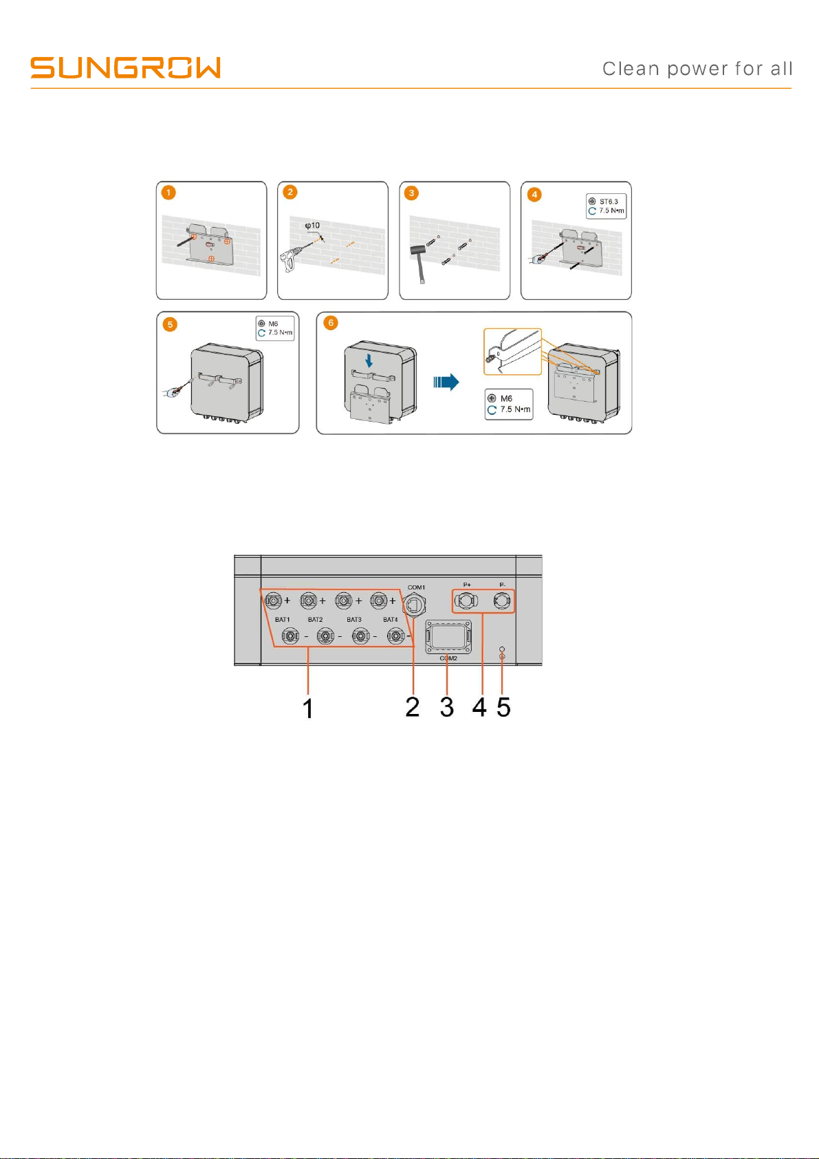
1.3 Mounting the Combiner Box
step 1 Install the wall-mounting bracket and mount the Combiner box to the bracket.
1.4 Terminal Description (Combiner Box)
All electrical terminals are located at the bottom of the combiner box.
figure 1 Terminals at the Bottom of the Combiner Box
* The image shown here is for reference only. The actual product received may differ.
GD_202201_Sungrow SBR HV Battery Parallel Extension Manual_V1.1 Page 4 of 18
© Sungrow Australia Group Pty. Ltd. All rights reserved.
As we continuously improving our services, changes to this document may occur without notice.
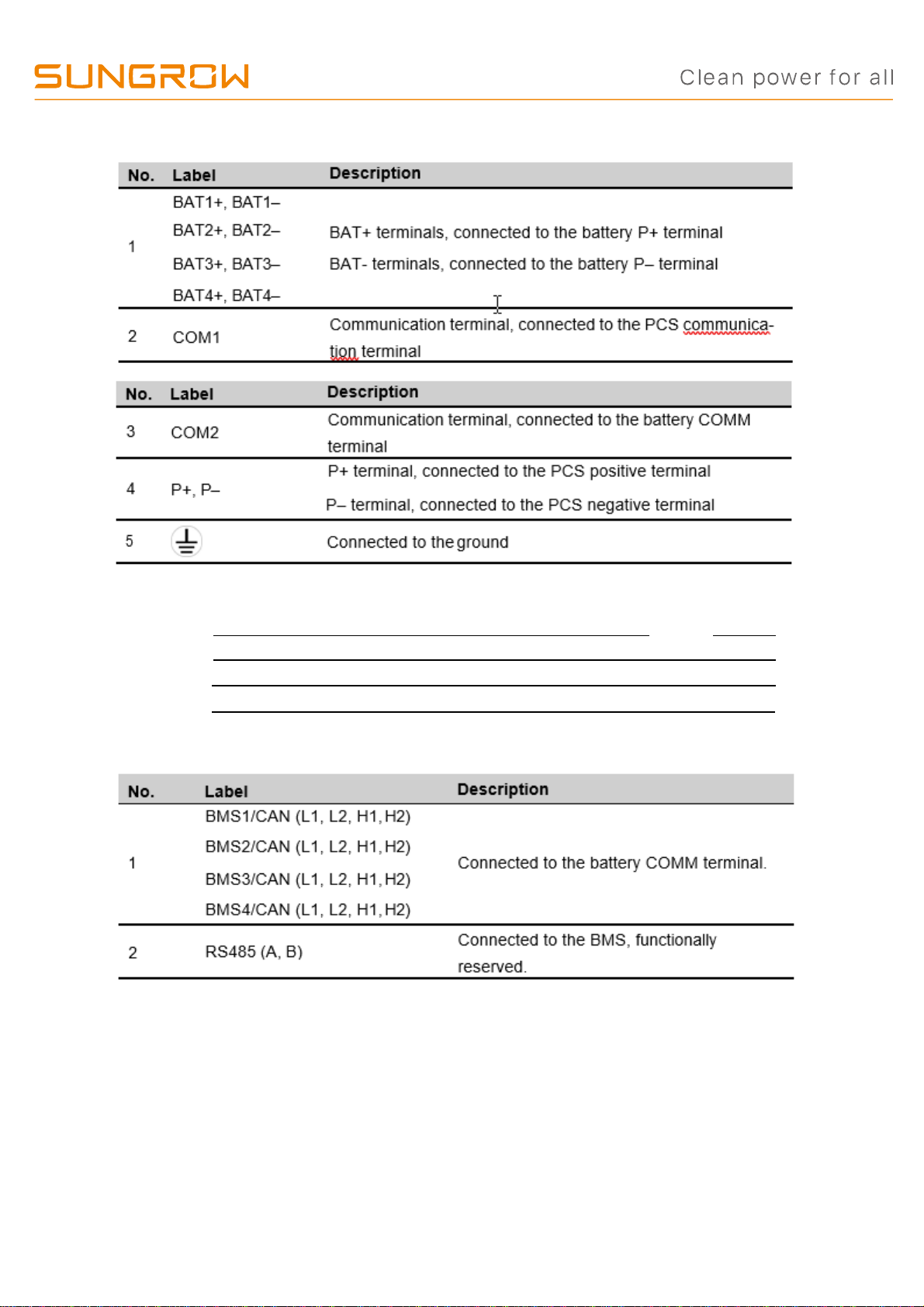
table 5-1 The label description of Combiner Box terminal
table 2 The label of COM2 terminal
L1
L2
L1
L2
L1
L2
L1
L2
A
H1
H2
H1
H2
H1
H2
H1
H2
B
BMS1/CAN BMS2/CAN BMS3/CAN BMS4/CAN RS485
table 3 The label description of COM terminal
GD_202201_Sungrow SBR HV Battery Parallel Extension Manual_V1.1 Page 5 of 18
© Sungrow Australia Group Pty. Ltd. All rights reserved.
As we continuously improving our services, changes to this document may occur without notice.
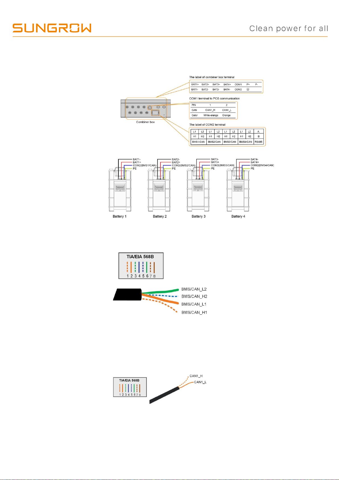
1.5 Connection Diagram in Parallel System
•
The COMM terminal of the battery is connected to the COM2 terminal of the combiner
box. Signal cable 1 white and orange cable is used as BMS/CAN_H1; signal cable 2 or-
ange cable is used as BMS/CAN_L1; signal cable 5 white and blue cable is used as
BMS/CAN_H2; and signal cable 6 green cable is used as BMS/CAN_L2.
•
The groundingterminalof thebattery is connected to the PEterminal of the combiner box.
•
The COM1 terminal of the combiner box is connected to the PCS. Signal cable 1 white
and orange cable is used as CAN1_H; and signal cable 2 orange cable is used as
CAN1_L.

GD_202201_Sungrow SBR HV Battery Parallel Extension Manual_V1.1 Page 6 of 18
© Sungrow Australia Group Pty. Ltd. All rights reserved.
As we continuously improving our services, changes to this document may occur without notice.
1.6 PE Cable Connection
step 1 Prepare an earth cable by shrink tub and lug.
step 2 Remove the screw on the PE terminal and fasten the cable with a screwdriver.
step 3 Apply paint to the grounding terminal to ensure corrosion resistance.
GD_202201_Sungrow SBR HV Battery Parallel Extension Manual_V1.1 Page 7 of 18
© Sungrow Australia Group Pty. Ltd. All rights reserved.
As we continuously improving our services, changes to this document may occur without notice.
1.7 Battery Connection (please use only the SUNCLIX connectors
provided in the box)
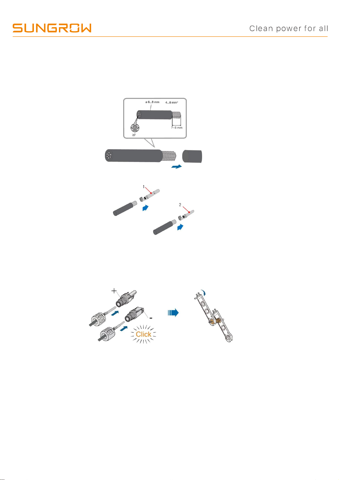
1.7.1 Assembling the Battery Connectors
step 1 Strip the insulation from each DC cable by 7~8 mm.
step 2 Assemble the cable ends with the crimping pliers.
1: Positivecrimp contact 2: Negative crimpcontact
step 3 Lead the cable through cable gland, and insert the crimp contact into the insulator until it snaps into
place. Gently pull the cable backward to ensure firm connection. Tighten the ca- ble gland and the insulator
(torque 2.5 N.m to 3 N.m).
step 4 Check for polarity correctness.

GD_202201_Sungrow SBR HV Battery Parallel Extension Manual_V1.1 Page 8 of 18
© Sungrow Australia Group Pty. Ltd. All rights reserved.
As we continuously improving our services, changes to this document may occur without notice.
1.7.2 Installing the Battery Connectors
step 1 Connect the Battery connectors to corresponding terminals until there is an audible click.
step 2 Seal the unused Battery terminals with the terminal caps.

GD_202201_Sungrow SBR HV Battery Parallel Extension Manual_V1.1 Page 9 of 18
© Sungrow Australia Group Pty. Ltd. All rights reserved.
As we continuously improving our services, changes to this document may occur without notice.
1.8 SUNCLIX Connection
step 1 For the assembly of the SUNCLIX connector, refer to the appendix.
step 2 Remove the waterproof lid from P+ and P–the terminal.
step 3 Plug the connectors into P+ and P–terminals.

GD_202201_Sungrow SBR HV Battery Parallel Extension Manual_V1.1 Page 10 of 18
© Sungrow Australia Group Pty. Ltd. All rights reserved.
As we continuously improving our services, changes to this document may occur without notice.
1.9 COM2 Cable Connection
1.9.1 Assembling the COM2 Cable Connector
The BMS3/CAN terminal is used as an example for description.
step 1 Unscrew the swivel nut from the connector.
step 2 Take out the terminal block.
step 3 Remove the seal and lead the cable through the cable gland.
step 4 Strip the cable with a wire stripper.
step 5 Crimp the cord end terminal 。
Table of contents
Other Sungrow Camera Accessories manuals


Popular Camera Accessories manuals by other brands

Viltrox
Viltrox EF-NEX Mount instructions

Calumet
Calumet 7100 Series CK7114 operating instructions

Ropox
Ropox 4Single Series User manual and installation instructions

Cambo
Cambo Wide DS Digital Series Main operating instructions

Samsung
Samsung SHG-120 Specification sheet

Ryobi
Ryobi BPL-1820 Owner's operating manual


