Sunny INV220 Series User manual

USER MANUAL For Central Battery Systems - INV220V Series

Table of Contents
Part 1 : Overview Central Battery Systems
Features
Technical Specifications
Indicators
Electrical Connector
Part 2 : Installation and Operation
Battery Connection
Steps for Connecting the Input and Output
Device Initialization
Part 3 : Maintenance
Device Maintenance
Initial Trouble Shooting
Important Note on Using the Unit
Testing the Unit’s Operability
1
Page
2
3
4
5
6
7-9
10-11
12
12
12
1.1
1.2
1.3
1.4
2.1
2.2
2.3
2.4
3.1
Part 4 : Terms for Warranty and Service
Terms for Warranty and Service 13
4.1
3.2
3.3

Part 1
Overview Central Battery Systems

Central Battery Systems by Inverter 220V is used to detect any abnormalities of the main power distribution
system. In case of error or emergency, the unit will convert the battery voltage stored in the chemical form into the
electric power and supply it to the inverter where the DC voltage from the battery will be converted into the AC
voltage at 220VAC 50Hz to turn on the emergency light. On the other hand, when the main power distribution
system resumes its normal operation, the unit will stop supplying the backup power and start recharging the battery
for later use in case of another error or for the emergency light test.
Central Battery Systems by Inverter 220V Series has 2 function modes of operation.
1.1
1
Transformer
DC
AC
Display
Rectifier Controller Power Inverter
Transfer
Transfer
Battery
Maintained
System
Non - Maintained
System
AC Input
220-240VAC
1.1 Features
1. MAINTAINED (Providing lighting constantly throughout the period when the AC line lights are in the normal
status and when the AC Line lights are off.)
2. NON–MAINTAINED (Providing emergency lighting only when the AC line lights are off.)

1.2 Technical Specifications
2
Model
Rated Capacity
(Wattage)
Mode of Operations
Input
Voltage
Frequency
Output
Voltage
Frequency
Output Wavefrom
Terminal Output
Maximum Load @ PF=1
(Wattage)
Efficiency
Battery Type
Battery Rated Voltage
Protections
Operate of
Temperature
Size L x W x H (mm)
INV220 Series
200 300 400 500 700 1000 1200 1500 2000 2500 40003000
2000 2500 40003000
Maintained and Non - Maintained
220 -240VAC
50Hz
AC220V± 2%
50Hz ± 1%
(Battery Mode)
2 Output
200 300 400 500 700 1000 1200 1500
>80%
Sealed Lead – Acid Battery
24V48V
10°C to50°C
440x230x660 600x250x810 640x250x970 620x400x1200 620x600x1200
(Battery Mode)
Pure Sine Wave
-Overload & Short circuit
-Battery Low voltage cut-off
-AC Input Low Voltage Protections
800x600x1500

1AC. VOLTMETER
2DC.VOLTMETER
3LED
AC. Input
4LED DC. Input
5LED Operate
6LED Testing
7LED Charging
8LED Battery Fail
9LED Charge Fail
Indicating the input and output voltage.
Indicating the battery voltage.
Indicating the status of the input voltage of 220-240VAC.
Indicating the status of the battery power into the device.
Indicating the operation status of the inverter unit.
Indicating automatic battery discharge status.
Indicating charging status.
Indicating the failure status of the battery.
Indicating the failure status of the battery charging.
1.3 Indicators
3
1
2
3
4
5
6
7
8
9
No. Symbol Description

1AC.INPUT 220VAC
2
3
1 BATT
2AC.INPUT 220VAC
3
4
1.4 Electrical Connector
4
MAINTAINED
NON - MAINTAINED
AC.INPUT 220VAC MAINTAINED NON-MAINTAINED
BATT
MAINTAINED
NON - MAINTAINED
Terminal for connecting power to the device
Terminal Maintained for Continuous Power Supply Mode
Terminal Non-Maintained for Use in Emergency Power Supply Mode
No. Symbol Description
Circuit Breaker for Battery Operation On/Off
Circuit Breaker for On/Off Power Supply to the Device
Circuit Breaker for On/Off Output Power

Part 2
Installation and Operation

4 Batteries in Series (48V)
Since the inverter operates at a voltage of 24 Volts and 48 Volts, for maximum efficiency the batteries
are connected together to increase its voltage from 12 Volts to 24 and 48 Volts as shown in the diagram
connecting the battery with the battery in the box connecting the positive (+) and negative (-) cables correctly.
1. Set all the breakers to Off prior to connecting the batteries.
2. Connect the cables to the correct battery terminal following the wiring diagram.
3. Do not short-circuit the battery terminals.
4. Check the Voltage of the battery after the connection to make sure if it is the desired 24 Volts or 48 Volts.
Warning
2 Batteries in Series (24V) 2 Parallel Sets of Batteries in Series (24V)
4 Batteries in Series (48V) 2 Parallel Sets of Batteries in Series (48V)
2.1 Battery Connection
5

1.) Test the readiness of the output load, for example, check for any short-circuits or if the total wattage
exceeds the acceptable load. (Caution: The Output Line and Neutral circuit should be independent from
other circuits otherwise damage could occur to the inverter.)
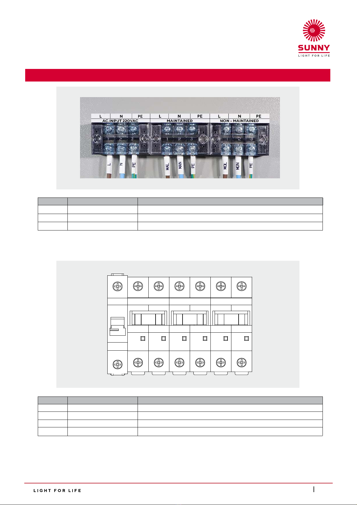
2.) When connecting to the Load Output in the circuit box there will be 2 outputs to choose from, which are
2.1 Output Maintained. This connection will provide a constant 220Vac 50Hz current. This is suitable
for uses that requires a constant current both during normal conditions and during power outages,
for example, providing power for emergency exit signs without a built-in battery or lights that need to be
constantly on such as lights installed in fire escapes or in parking lots.
2.2 Output Non-Maintained. This connection will not provide a 220Vac 50Hz during normal conditions.
The connection will only provide power during power outages. This connection is suitable for things such
as emergency illumination lamps.
Caution: For the correct connection the Line should be connected into L, Neutral should be connected to N and
Ground should be connected to PE The cables should be connected securely and no foreign objects should be in
the circuit box that could potentially cause a short-circuit.
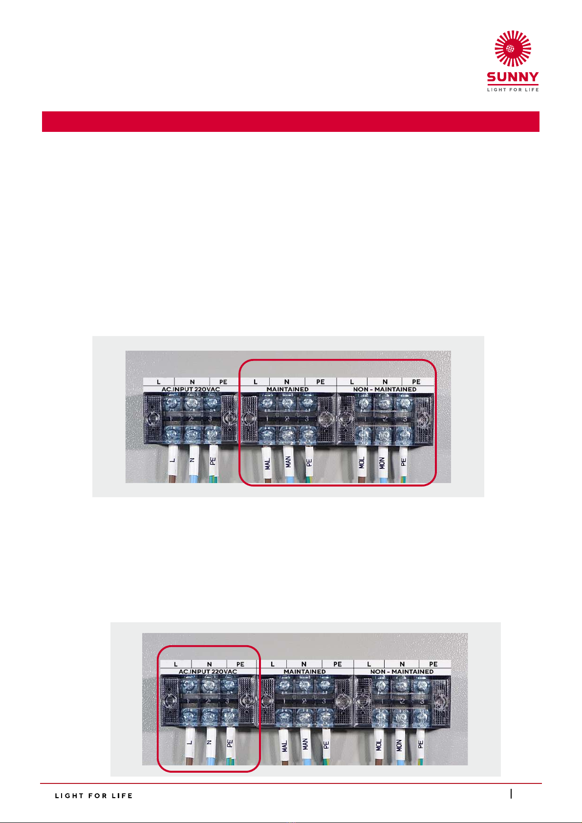
3.) Connect the Input cables to the Input 220VAC terminal inside the red frame inside the circuit box. The Line
cable should be connected to the L terminal, the Neutral cable to the N terminal and the Ground cable to the PE
terminal. The cables should be connected securely and no foreign objects should be in the circuit box that could
potentially cause a short-circuit.
2.2 Steps for Connecting the Input and Output
6

The display of device operation
1.) Turn on the Circuit Breaker BATT and the Circuit Breaker AC INPUT 220VAC (as indicated by the
red frame). The device will begin charging the battery and enter a ready-to-use state. The front of the
device will display the following status:
2.3 Device Initialization
7
DC. VOLTMETER
Shows a battery Voltage at 24V or 48 V.
LED DC. Input
The indicator showing that the battery has been
connected to the unit should be on.
LED Charging
The indicator showing that the battery is charging.
LED AC. Input
The indicator showing that the unit is receiving
a 220-240VAC current should be on.
AC.INPUT 220VAC MAINTAINED NON-MAINTAINED
BATT
AC. VOLTMETER
Shows the current level at the Input to be
about 220-240VAC.

The display of device operation
2.) Set the Breaker AC.Input 220VAC to Off, the inverter will start operation as the same time set the
Breaker MAINTAINED, NON-MAINTAINED to On (shown in the red marking), the unit should now be
providing power to the load.
8
AC. VOLTMETER
Shows the current level at the Output to be
about 220VAC.
DC. VOLTMETER
Shows a battery Voltage at 24V or 48 V.
LED DC. Input
The indicator showing that the battery has
been connected to the unit should be on.
LED Operate
The indicator showing that the inverter is
operational should be on.
AC.INPUT 220VAC MAINTAINED NON-MAINTAINED
BATT

9
AC.INPUT 220VAC MAINTAINED NON-MAINTAINED
BATT
3.) Test to see if the overall current level and load stability is at a normal level.
4.) Set the Breaker AC.Input to ON (shown in the red marking), after the unit should stop using the inverter
and use the main power supply to provide power instead.
The display of device operation
DC. VOLTMETER
Shows a battery Voltage at 24V or 48 V.
LED DC. Input
The indicator showing that the battery has been
connected to the unit should be on.
LED AC. Input
The indicator showing that the unit is receiving
a 220-240VAC current should be on.
AC. VOLTMETER
Shows the current level at the Input to be
about 220-240VAC.
LED Charging
The indicator showing that the battery
is charging.

2.4 Testing the Unit’s Operability
1.) To test the unit, the user can set the Circuit Breaker AC Input 220VAC to OFF (shown in the red markings),
the unit should start providing backup power to the emergency lights immediately.
2.) To stop the test, the user can set the Circuit Breaker AC Input 220VAC back to ON. The inverter should
stop operating and the unit should return to standby mode.
3.) The unit has a built-in self-testing system that will perform 30 minutes self-tests every 30 days.
This self-test system should start working once a current from AC. Input is provided to the unit.
10
AC.INPUT 220VAC MAINTAINED NON-MAINTAINED
BATT
The display of device operation
DC. VOLTMETER
Shows a battery Voltage at 24V or 48 V.
LED DC. Input
The indicator showing that the battery has been
connected to the unit should be on.
LED AC. Input
The indicator showing that the unit is receiving
a 220-240VAC current should be on.
AC. VOLTMETER
Shows the current level at the Input to be
about 220-240VAC.
LED Testing
The indicator showing that the unit automatically
testing itself.

4.) If during the self-tests the battery is found to be faulty and cannot hold a charge or less charge that
normal the unit will show a “Battery Fail” warning.
Note: You can reset the alert by turning off and on the Circuit Breaker AC INPUT 220VAC and Circuit Breaker BATT.
5.) In the event that there is an abnormality in the battery charging system, such as over-charging voltage,
inability to charge, and charging for more than 24 hours, the unit will display the "Charging Fail" status.
Note: You can reset the alert by turning off and on the Circuit Breaker AC INPUT 220VAC and Circuit Breaker BATT.
11
LED Battery Fail
An LED will blink 3 times every 15 seconds
to indicate that the fail battery.
LED Charge Fail
An LED will blink 4 times every 15 seconds
to indicate that there is a problem charging
the battery
The display of device operation
DC. VOLTMETER
Shows a battery Voltage at 24V or 48 V.
LED DC. Input
The indicator showing that the battery has been
connected to the unit should be on.
LED AC. Input
The indicator showing that the unit is receiving
a 220-240VAC current should be on.
AC. VOLTMETER
Shows the current level at the Input to be
about 220-240VAC.

Part 3
Maintenance

1.) Keep ventilation fan of the unit clean.
2.) The unit has an Automatic testing system, automatically enabling 30 minute test every 30 days. If your unit
does not have a self-test system you should manually test the unit once a month for 30 minutes to make
sure the unit is fully operational and to help extend the life of the battery.
3.1
3.2 Central Battery Control Unit
1.) Please read the manual carefully before installation and operation
2.) Installation area should be good ventilation.
3.) Do not connect the battery in reverse polarity.
4.) Check the power load before installing the unit.
5.) Do not use with the power load when it is in an unstable condition.
6.) The power load must be an emergency light only. Do not use with the other power load that is
not approved by the manufacturer.
7.) The unit should be stored in temperatures under 25 Degree Celsius and the battery should be
charged every 3 month to maintain its operational life.
3.3 Important Note on Using the Unit
- 220-240 VAC Power not getting to
the unit.
- The Backup power supply of the unit
has failed.
- Emergency light only turns on for
a short time after the power went out.
- The power socket might not have any
power.
- Circuit Breaker AC. Input is in the
OFF status.
- Circuit Breaker DC. Battery is in
the OFF status.
- Circuit Breaker AC. Output is in
the OFF status.
- The battery is not fully charged.
- The battery has degraded.
- Check to make sure that the power socket of
the home or building is providing a 220VAC
current.
- Check to make sure that theCircuit Breaker
AC. Input is in the ON position.
- Check to make sure that the Circuit
Breaker DC. Battery is in the ON position.
- Check to make sure that the Circuit
Breaker AC. Output is in the ON position.
- Fully charge the battery.
- Contact customer service to replace
the battery.
3.2 Initial Trouble Shooting
3.1 Device Maintenance
12
Cause Problem What to do

Part 4
Terms for Warranty and Service

13
3.1
4.1 Terms for Warranty and Service
1. The Warranty will only be covered if the customer fills in the “warranty registration form” and
mail the return part back to the company within 7 days from the day of purchase. If this is not
carried out the warranty will be considered void.
2. The warranty only covers the unit’s internal parts. The conditions and durations for the warranty of
each part is as specified and the duration of the warranty is calculated from the date of purchase.
3. Please show your warranty card every time you contact our service center or the dealer you
purchased the product from.
4. Products that fall into the following category are considered not covered by the warranty.
4.1 The product was used in a way not specified in the manual.
4.2 The product was used with accessories not meeting the required specifications specified in
the manual.
4.3 The product seems to have been damaged from being dropped or from strong impact, for
example, the parts are loose, dented, scrapped or misshapen.
4.4 The product has been repaired or modified by personnel not authorized by our company.
4.5 The Warranty Void sticker is torn or removed.
4.6 The product is damaged from careless use or incorrect maintenance, for example, the battery
is swollen from overcharging, quick charging was used on the battery, the battery terminals
have been short-circuited, the unit was used until the battery was completely discharged and
not recharged immediately, the product was stored for long periods until the Battery Checker
warning activates and still it is not plugged-in to charge or taking the battery to normal
temperature conditions and not recharging it every 1 month.
4.7 The product was stored in an unsuitable environment, for example, a location with moisture
or water vapor.
4.8 The product was supplied with a faulty AC power supply such as electrical overvoltage,
electrical current surges, or lightning strikes entering the AC power line.
4.9 Damages from natural causes such as fire, being summered in fluids, humidity, chemicals or
force majeure.
4.10 Damages from insects or animals.
Note : Please read the manual carefully before installation and operation to understand how to
properly operate the unit.

Contact us
Specifications subject to change without notice.
© Ison Import-Export Co.,Ltd. All Right Reserved.
www.sunnyemergencylight.com
ISON IMPORT-EXPORT CO., LTD.
Head Office 2915-2917 Ladprao Road,
Klongjan, Bangkapi, Bangkok 10240
phone 02 378 1034-5
fax 02 370 1672
Table of contents
Popular Power Supply manuals by other brands

Keithley
Keithley 244 instruction manual

Whelen Engineering Company
Whelen Engineering Company ISP94A installation guide

Crestron
Crestron CSA-PWS10S-HUB-ENET installation guide

Matsusada Precision
Matsusada Precision EJC Series instruction manual

Rigol
Rigol DP800 Series quick guide

Wetekom
Wetekom 82 14 63 instruction manual