SunnyBrook Mobile Scout Titan 2006 User manual


Table of Contents
Introduction . . . . . . . . 3
Obtaining Service . . . . . . . . 4
Tow Vehicle Recommendations . . . . 5
Trailer Loading . . . . . . . . . 5
Hitch Connection . . . . . . . . . 8
Suspension & Tires . . . . . . . . . 10
Brake Systems . . . . . . . . . 15
Electrical Systems . . . . . . . . 17
Fresh Water System . . . . . . . . . 19
Holding Tanks & Drainage System . . . 21
Propane Gas System . . . . . . . . 22
Operation . . . . . . . . . . 25
Interior Care . . . . . . . 27
Exterior Care . . . . . . . . . . 27
Storage . . . . . . . . . . 29
Maintenance . . . . . . . . 30
Additional Precautions . . . . . 32
Rev. 0805


Introduction
SunnyBrook RV’s management and employees welcomes
you to our growing family of Travel Trailer and Fifth
Wheel owners. Since SunnyBrook RV’s inception in 1992,
our goal has been to provide towable recreational vehicles
designed and engineered to give many years of enjoyment
to our customers, who love the great outdoors. This manual
has been compiled to assist campers, both novice and
experienced in set-up, use, and preventative maintenance
for continued like-new appearance and performance from
their travel trailer or fifth wheel.Like finely crafted
furniture or highly engineered automobiles, SunnyBrook
& Mobile Scout travel trailers and fifth wheels require
care and regular maintenance to retain maximum
performance characteristics. If, after taking delivery of
your new trailer, it requires additional adjustment, please
return the trailer to your dealer as soon as possible. This
Owner’s Manual, along with information provided in your
Owner’s Information Package, outlines important areas
of maintenance and provides maintenance schedules to
ensure safe, trouble-free service. Knowledge of trailer
usage, components and maintenance will help you enjoy
many miles and years of recreational living.
INITIAL DEALER RESPONSIBILITY
SunnyBrook RV employees assemble travel trailers and
fifth wheels to standards, which meet or exceed local, state
and national codes. Each trailer has been thoroughly
inspected at our facilities prior to shipment. Every
SunnyBrook & Mobile Scout dealer has the responsibility
to re-inspect and to prepare every travel trailer and fifth
wheel during the pre-delivery phase of the sale. Dealership
personnel will provide instruction in basic trailer use and
features plus complete a pre-delivery inspection with you.
Dealership pre-delivery instruction and inspections should
be supplemented by a thorough review of all material
furnished with the trailer by SunnyBrook RV and
component and appliance manufacturers.
The dealer/customer pre-delivery instruction and
inspection should review:
§TOW VEHICLE/TRAILER CONNECTIONS
§TRAILER CONNECTION MAINTENANCE
§COUPLING & UNCOUPLING
§BREAKAWAY SWITCH
§TRAILER LOADING
§EXTERIOR INSPECTION
§INTERIOR DÉCOR INSPECTION
§EMERGENCY EXITS
§FIRE EXTINGUISHER
§DOOR, WINDOW & LOCK OPERATIONS
§FRESH WATER SYSTEM OPERATION
§WATER PUMP OPERATION
Pre-Delivery Inspection (Cont.)
§WASTE WATER SYSTEM OPERATION
§WATER HEATER OPERATION
§LAVATORY AND TUB/SHOWER CARE
§CONVERTER FUNCTION & OPERATION
§GROUND FAULT INTERRUPTER (GFI)
§CIRCUIT BREAKERS
§INTERIOR LIGHTS, SWITCHES & RECEPTACLES
§REFRIGERATOR OPERATION
§RANGE OR RANGE/OVEN OPERATION
§FURNACE OPERATION
§OPERATION OF OTHER APPLIANCES
§MONITORING PANEL FUNCTIONS
§PROPANE GAS SYSTEM & PROPANE
LEAK DETECTOR
§TV ANTENNA & RELATED COMPONENTS
§AWNINGS
§BED CONVERSIONS
§CURTAINS, CARPET & COUNTERTOPS
§TABLE SETUP & STORAGE
§SPARE TIRE CARRIER
§EXPLANATION OF SUNNYBROOK WARRANTY
§EXPLANATION OF COMPONENT & APPLIANCE
WARRANTIES
§ACCEPTANCE OF TRAILER CLEANLINESS
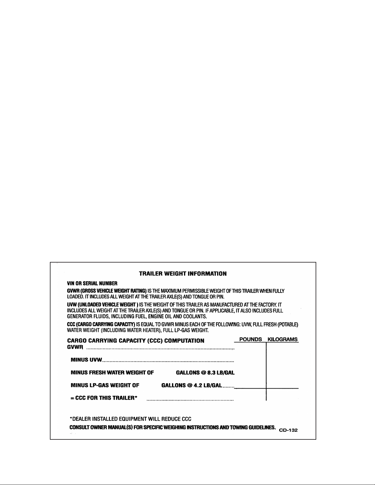
§WEIGHT DISTRIBUTION
GENERAL INFORMATION
The Owner’s Manual will provide general information and
instruction. Product information or instruction may not
apply, may be excluded or may be generalized because:
§Equipment and features described or shown may
be optional or unavailable on some models.
§Ongoing design changes may not be included
because of continuous product improvement.
§Specifications may change without notice.
Descriptions or photographs in this manual are
representative of function and may not specifically depict
actual equipment, fabrics, interior or exterior décor or
design options as installed with your trailer.
THIS PRODUCT IS DESIGNED FOR
RECREATIONAL USE AND SHORT-TERM
OCCUPANCY ONLY.
SunnyBrook travel trailers and fifth wheels are not
designed or intended to be used as permanent housing.
Using this product for long term or permanent occupancy
may lead to premature deterioration of appliances,
plumbing, interior finishes, fabrics, carpeting and drapes.
Damage or deterioration due to long term occupancy is
not considered normal, and constitutes misuse or abuse
under the warranty terms, therefore voiding your warranty
protection.
3

Obtaining Service
Make an Appointment
Always make an appointment in advance with the service
center. Schedule as far in advance as possible, then confirm
the appointment as the date approaches. Do not show up
without an appointment for service and expect that the
service center will be able to “fit you in”. Arriving without
an appointment may cause additional aggravation when
your request is met with “I’m sorry but our schedule is
full for the next four weeks.”
Preparation for an Appointment
If you have made an appointment to have warranty service,
be sure to have the correct papers with you. Take your
Warranty Registration paperwork and owner’s packet with
you to your appointment. Not all work to be performed
may be covered by the warranty. Keep a maintenance log
of your trailer’s service history. This can often provide a
clue to the current problem.
Prepare A List . . .
Make a written list of your trailer’s problems or the specific
work you would like completed. If you’ve had an accident,
or work done that is not on your maintenance log, let the
service advisor know. Don’t keep secrets.
Be Reasonable With Requests . . .
If you list a number of items, and you must have your
trailer by the end of the day, discuss the situation with the
service advisor and list the items in order of priority. Please
do not expect to add to the list for service beyond what
you have previously scheduled when you arrive for your
appointment. Even though the service center may be able
to complete the additional requests, their schedule has been
determined based or your original request.
If You Need Assistance . . .
SunnyBrook RV and our dealers are vitally interested in
your satisfaction. We want you to be happy with our
products and services.
Your selling dealer is best equipped and most anxious to
provide prompt resolution for any warranty issue or related
matter that you may experience. SunnyBrook RV dealers
have the facilities, trained technicians, special tools and
the latest information to assure your trailer is fixed
correctly and in a timely manner.
If special circumstances arise, always talk to your dealer’s
service manager first. Most matters can be resolved with
this process. If for some reason your are still not satisfied,
talk to the general manager or owner of the dealership.
They want to know if you need assistance. If your
dealership is unable to resolve the concern, you may
contact SunnyBrook Customer Service.
Any communication to SunnyBrook Customer Service
should include the following information:
qOwner’s Name and Address
qOwner’s Telephone Number
qDealership Name
qTrailer Identification Number
qTrailer delivery date
Inspecting Repairs
SunnyBrook RV and your servicing dealer want you
to be satisfied with any repair. After a repair is per-
formed, inspect the workmanship carefully. Check
your service list and go over the repairs with the ser-
vice center representative. Once satisfied, sign the
SunnyBrook RV claim form. In the event a problem
should reoccur after you have left the dealership, con-
tact the repair center or SunnyBrook RV as soon as
possible, so that the situation can be resolved in a
timely manner.
4

Tow Vehicle
Recommendations
MANUFACTURER SPECIFICATIONS
SunnyBrook RV travel trailers and fifth wheels can be
towed by many types of vehicles. When selecting a tow
vehicle for travel trailers and fifth wheels, complying with
vehicle manufacturer specific recommendations
concerning towing capabilities and restrictions is critical.
Many vehicle manufacturers and dealers can provide
special towing packages based on specific requirements,
such as trailer size, maximum trailer load and tow vehicle
demands during travel (i.e. terrain, trip lengths, etc.).
VEHICLE TUNE-UP
Proper vehicle maintenance is necessary including engine
tune-ups and lubrication. An engine may overheat on long
upgrades, which may be prevented with a larger, heavy-
duty radiator and proper care.
BATTERY AND ALTERNATOR
During travel the tow vehicle battery and alternator must
support some of the trailer’s electrical equipment including
taillights, turn signals, brake lights, clearance lights and
electric brakes. The battery and alternator must be in good
condition and able to handle this load.
HITCHES
Many types and ratings of trailer hitches are available.
Important factors when selecting the proper hitch are:
§Follow the tow vehicle manufacturer’s and the hitch
manufacturer’s recommendations to ensure proper
installation and size requirements.
§Keep the tow vehicle and the trailer level to maintain
equal weight distribution and ensure maximum
steering control.
§Heavier springs and/or overload shock
absorbers will help increase hitch load capacity.
ELECTRONIC BRAKE CONTROLLERS
Many types of electronic brake controllers are available.
Consult your dealer to determine specific needs. Insist that
any electronic brake controller be installed per the
manufacturer’s instructions. It may be necessary to install
a resistor in the trailer’s braking system. If the trailer skids
or the brakes grab, a resistor in the circuit may remedy the
problem. Follow the individual resistor’s instructions. Do
not use more than one resistor in the circuit.
REAR VIEW SIDE-MOUNTED MIRRORS
Rear view, side-mounted mirrors on both driver and
passenger sides of the tow vehicle are a necessity. Side-
mounted mirrors provide a clear view of following traffic
and an unobstructed view of the trailer action. They should
be properly extended offering an unobstructed view of the
rear of the trailer and possible traffic hazards.A travel
trailer chassis (springs, wheels, tires axles, frame and
tongue) is engineered to carry certain maximum load.
Trailer Loading
WEIGHT DISTRIBUTION
Proper weight distribution between axles and tongue is
also critical to safe towing. Factors to consider when
evaluating proper weight distribution are:
§On travel trailers, tongue proportion of the GROSS
VEHICLE WEIGHT should be approximately 10%
to 15% for tandem axle trailers. Depending on the
tow vehicle, 11% to 12% tongue-weight is ideal.
Hitch weight proportion on fifth wheels is a larger
percentage of the GROSS VEHICLE WEIGHT.
§Proper distribution required for towing stability, assures
the trailer is not rear, front, or side heavy.
§A light tongue weight or heavy weight placed at the
rear end of the trailer may cause trailer sway.
Too much weight on the tongue can overload the tow
vehicle, and cause poor tow vehicle stability and handling,
poor braking, poor cornering, and may damage the trailer
frame.
TRAVEL TRAILER EQUALIZER HITCHES
Travel trailer load equalizer hitches can add 33% plus or
minus of hitch weight to trailer axles when the trailer and
tow vehicle are level. If the tow vehicle tilts front or rear,
the tension on the equalizer bars will affect the amount of
weight distributed to the axles.
REAR BUMPER LIMITATIONS
The rear bumper of a travel trailer or fifth wheel is not
intended to be a weight bearing structure. The bumper is
not capable of supporting any additional weight beyond
that of the tire carrier and spare tire. Besides being unable
to support added weight, adding weight to the rear of the
travel trailer will affect the hitch weight and the stability
of the trailer while towing.
WARNING: The rear bumper of travel trailers and
fifth wheels are not intended to be used as steps and
are not designed to support more than 70 pounds.
5

WEIGHT RATINGS
The Trailer Weight Information label (located inside the
kitchen sink cabinet door on almost all trailers and fifth
wheels) provides weight data critical to understanding
the maximum load of a travel trailer or fifth wheel:
GROSS VEHICLE WEIGHT RATING (GVWR) is
the maximum permissible weight of the trailer. The
weight of the empty trailer, plus weight added in the form
of water, food, clothing, and anything else in or attached
to the trailer must not exceed the GVWR. In other words,
the GVWR is equal to or greater than Unloaded Vehicle
Weight plus the Cargo Carrying Capacity.
The UNLOADED VEHICLE WEIGHT (UVW) is the
weight of the travel trailer or fifth wheel as manufactured.
This is the weight on the trailer axles and tongue or pin.
CARGO CARRYING CAPACITY is the maximum
weight of personal belongings, food, fresh water,
PROPANE gas tools, accessories, etc. that can be loaded.
The GROSS AXLE WEIGHT RATING (GAWR)
represents the allowable empty vehicle’s axle weight plus
Cargo Carrying Capacity excluding the hitch weight. The
weight is divided between each axle and each has its own
GAWR. The total of axle load plus the tongue weight
must not exceed the trailer GVWR. The GAWR is located
on the manufacturer’s Federal ID label on the left sie
front corner outside the trailer.
DETERMINING TRAILER WEIGHT
To determine the weight of a loaded trailer:
1.Locate public weight scale.
2.Park your trailer and disconnect it on the scale. Both
wheels and jacks should be on the scale.
3.The reading will be the Gross Vehicle Weight of the
trailer and should not exceed the GVWR as indicated
on the manufacturer Federal ID tag.
To determine Gross Axle Weight - Both Axles:
1.Leave trailer connected to the tow vehicle.
2.Be certain the trailer is level.
3.Leave the tow vehicle off the scale.
4.Roll forward far enough so both trailer axles are on
the scale.
5.The reading will be the Gross Axle Weight for both
axles.
To determine Gross Axle Weight - Each Axle
1.Leave trailer connected to the tow vehicle.
2.Be certain the trailer is level.
3.Leave the tow vehicle off the scale.
4.Roll forward far enough so only rear trailer axle (two
tires) is on the scale.
5.The reading will be the Gross Axle Weight for the
rear axle.
6.Subtract the total Gross Axle Weight from the rear
axle weight to calculate the front axle weight.
Sample Trailer Weight Information Label
This label is affixed inside a lower sink cabinet door in most travel trailers & fifth wheel
6

To determine hitch weight:
1.Subtract the total Gross Axle Weight reading from the
Gross Vehicle Weight reading. This figure is the loaded
hitch weight.
2.If equalizer equipment is installed, this will affect both
hitch and axle weight
IMPORTANT:
§Determine hitch and axle weights with both vehicles
level.
§Tilting the trailer forward will add front axle weight.
§Hitch weight and tension of the equalizer bars will
be affected by leveling the trailer and tow vehicle.
§Have the tow vehicle level if equalizers are used.Have
tire pressure up to specifications as indicated on the
tire sidewall.
Consider load weights when determining weight
distribution. Proper trailer positioning and loading
are important not only for ease of hauling, but for
safety. Remember: 10% to 15% of a travel trailer’s
weight should be on the hitch. A fifth wheel will be
slightly more as a percentage.
Heavier items should be placed over the axles. Avoid
placing too much weight at the front or rear of the trailer.
Excess weight in/on the rear of the trailer can have a
negative effect on the stability of both vehicles.Stability
and weight can be affected if waste is in the holding tanks
or water in the fresh water holding tank.
CAUTION: Do not attach such items as motorcycles,
fuel or water containers, etc. on the rear of your trailer.
SECURE FOR TRAVEL
Before starting out, make certain everything is secure in
the trailer.
§Check cabinets and drawers; make sure nothing can
spill in cabinets or refrigerator.
§Ensure that the refrigerator latch is engaged.
§Lock windows and rockguards.
§Close roof vents.
§Secure loose chairs and other items.
§Disconnect all hoses and close all valves.
§Make sure electrical cords and adapters have been
disconnected and put away.
7

Hitch Connection
Using the proper hitch on the tow vehicle is critical for
maximum safety when towing a travel trailer. Load-
leveling or load-equalizing hitches with anti-sway bars are
recommended for added stability and maneuvering.
Several factors need to be considered when selecting the
proper hitch including:
§Gross weight of the trailer.
§Tongue weight.
§A welded or bolted weight-carrying hitch on the frame
or body of the tow vehicle.
§A 2 5/16 inches hitch ball. (Lubricate the hitch ball
periodically).
Consult your dealer and/or a representative of your tow
vehicle manufacturer in selecting a hitch and accessories
for your trailer.
SAFETY CHAINS
The Department of Transportation federally mandates use
of safety chains on travel trailers. Safe towing
recommendations include:
§Attach safety chains to the tow vehicle separate from
the hitch.
§Leave only enough slack in each length of chain to
permit the vehicle to turn during normal driving.
§The chains should not contact the ground or road
surface.
§Cross the chains from the trailer hitch to the tow
vehicle.
§When all connections are secure, be certain the 7-pin
electrical connector cord and the breakaway switch
lanyard cable are longer than the extended safety
chains.
§Should the hitch ball become disengaged from the
coupler, the safety chains will extend, the 7-pin
connector should remain connected to the tow vehicle
for braking and the breakaway switch should not
engage.
VEHICLE & TRAILER HOOK-UP
Connecting the tow vehicle hitch to the coupler on the
travel trailer or fifth wheel is a simple procedure, described
by the following:
TRAVEL TRAILERS
1.Before dropping the coupler over the hitch ball, the
coupler-locking arm must be in an unlocked position.
2.The coupler should be slightly behind the ball (away
from the tow vehicle), permitting the coupler to slide
down over the ball positively.
3.After locking the coupler over the ball, be certain the
ball is fully engaged with the coupler.
4.Attach the safety chains to the tow vehicle. Be sure to
cross the chains from the trailer hitch to the tow
vehicle. Be careful to leave slack in each length of
chain to permit the vehicle to turn during normal
driving.
5.Check the vehicle’s turning capabilities.
6.Attach the connector plug on the trailer to the electrical
connection on the tow vehicle. Be sure there is slack
in the cord to make sharp turns.
7.The breakaway device is located on the trailer tongue.
It has a steel cable fastened to it, which will reach to
the frame of the tow vehicle. The steel cable (lanyard)
should be attached to a secure part of the tow vehicle,
separate from the hitch, such as the frame.
8.The breakaway device is connected to the trailer
battery and will operate independently to apply the
trailer brakes should the trailer become disconnected
from the tow vehicle.
9.Apply trailer brakes only and proceed very slowly to
confirm proper engagement of the hitch and brake
operation.
10.Test all exterior lights on the trailer.
FIFTH WHEELS
1.Open the hitch locking device in the truck.
2.Lower the tailgate of the truck. NOTE: If not required,
the rear tailgate can be removed to simplify coupling
and uncoupling.
3.Back the truck to engage the kingpin in the hitch latch
plate. It is important the pinbox and hitch latch plate
are as level as possible.
4.Latch plates will engage the kingpin automatically on
some hitches, but the handle grip must be pushed to
the locked position (see manufacturer’s instructions
for full details). On other hitches, the lever will be
used to engage the kingpin (manually) and to lock it
in position.
5.Visually check that the hitch is locked to the small
diameter portion of the kingpin.
6.Raise the tailgate of the truck.
7.Raise the front jacks of the fifth wheel trailer.
8.Plug the electrical connector cord into the receptacle
on the truck.
9.Attach the safety cable for the breakaway device to
part of the truck hitch. Keep the cable in a straight
line with the switch on the trailer as much as possible
and allow enough slack for turns.
10.Apply trailer brakes only and proceed very slowly
to confirm proper engagement of the hitch.
11.Test operation of all exterior lights on the trailer.
8

BREAKAWAY DEVICE
Should your trailer become completely disconnected while
being towed, the breakaway device is designed to actuate
the trailer brakes and bring it to a stop, preventing a
runaway trailer. The switch has a pull-pin linked to the
tow vehicle with a steel cable; the cable pulls the pin free.
This causes two contacts in the device to go together,
immediately closing the circuit between the trailer battery
and the trailer brakes.
CAUTION: Never tow a trailer without the trailer battery
being hooked up and fully charged. Attach the breakaway
lanyard cable so it is longer than the safety chain. When
connected to the vehicle, the pull on the pin is in a straight
line with the cable. Do not hook the cable over the trailer
ball.
9

Suspension & Tires
The suspension system of your new travel trailer or fifth
wheel consists of tandem axles, leaf-type springs, wheels,
tires and electric brakes on each wheel. The following is
an overview of these components:
AXLES & LEAF SPRINGS
Our travel trailers and fifth wheels axles are suspended
on heavy-duty, double-eye leaf springs designed to absorb
sharp jolts from the road, prevent jolts from being
transmitted to the trailer and maintain full tire contact with
the road.
Spring shackle mounts are welded to the frame of travel
trailers. Adjustable, multi-hole, plate mounts are welded
to fifth wheel frames. The springs and shackle bolts are
self-lubricating. Check the shackle bolts periodically for
tightness. Do not reuse shackle bolts/nuts, if an axle must
be removed. Self-locking nuts must be replaced if removed.
TIRES
We use only premium quality radial tires. All tires meet
or exceed load and wear specifications for trailers. Proper
inflation pressure must be maintained for safe trailer
stability and maximum tire life. Load range and maximum
cold inflation pressure are stamped on the sidewall.
Always inflate the tires to this maximum pressure.
A tire gauge should always be part of your tool kit. Check
tire pressures before starting out, when the tire is cold.
Do not bleed air out of warm tires. Inflation specifications
are for cold tires.
Inflate the rear tires of the tow vehicle to the maximum
cold inflation pressure stamped on the tire sidewalls.
Higher rear tire pressure improves tow vehicle stability.
WARNING: CHECK TIRE PRESSURES OFTEN. ALWAYS
CHECK PRESSURE WHEN TIRES ARE COLD. DO NOT
EXCEED MAXIMUM RECOMMENDED PRESSURE
.WARNING: KEEP TIRES PROPERLY INFLATED. TIRES MAY
LOSE AIR SUDDENLY AND/OR CATCH FIRE, IF DRIVEN FOR
LONG DISTANCES OR AT HIGH SPEEDS WHILE SERIOUSLY
UNDER INFLATED. TIRES COULD OVERHEAT WHERE
DAMAGE TO THE VEHICLE, CONTENTS AND/OR
PERSONAL INJURY MAY OCCUR.
CHANGING TIRES
1.Turn on the tow vehicle’s hazard warning flashers.
2.Set up flares or warning lights.
3.Chock the opposite tire and unhitch the trailer from
the tow vehicle, or eliminate tension on equalizer bars,
if applicable.
4.Place scissors-type or hydraulic jack on a block of
wood directly under the frame, close to the tire you
intend to change.
CAUTION: When using bottle-type jacks, a metal plate
or block of wood to relieve stress against the steel frame
should be inserted between jack and frame. DO NOT
use a bumper jack. It may damage the sidewalls or
floorboard of the trailer.
5.Raise the jack to take weight off the tire.
6.Loosen the lug nuts.
7.Raise the jack until the tire clears the ground.
8.Remove the lug nuts and old tire and put the spare on
the hub.
9.Replace and tighten the nuts.
10.Lower the jack until the tire touches the ground.
11.Tighten the lug nuts to a torque of 90 to 95 ft. lbs.
12.Lower and remove the jack.
13.Hook up equalizer bars, if applicable.
14.CHECK THE TORQUE IMMEDIATELY.
The National Traffic Safety Administration (NHTSA)
has published a brochure (DOT HS 809 361) that
discusses all aspects of Tire Safety, as required by CFR
575.6. This brochure is reproduced in part below. It
can be obtained and downloaded from NHTSA, free
of charge, from the following web site:
http://www.nhtsa.dot.gov/cars/rules/
TireSafety/ridesonit/tires_index.html
Studies of tire safety show that maintaining proper
tire pressure, observing tire and vehicle load limits
(not carrying more weight in your vehicle than your
tires or vehicle can safely handle), avoiding road
hazards, and inspecting tires for cuts, slashes, and other
irregularities are the most important things you can
do to avoid tire failure, such as tread separation or
blowout and flat tires. These actions, along with other
care and maintenance activities, can also:
• Improve vehicle handling
• Help protect you and others from avoidable
breakdowns and accidents
• Improve fuel economy
• Increase the life of your tires.
10

This manual presents an overview of tire safety,
including information on the following topics:
• Basic tire maintenance
• Uniform Tire Quality Grading System
• Fundamental characteristics of tires
• Tire safety tips.
Use this information to make tire safety a regular part
of your vehicle maintenance routine. Recognize that
the time you spend is minimal compared with the
inconvenience and safety consequences of a flat tire
or other tire failure.
Safety First–Basic Tire Maintenance
Properly maintained tires improve the steering,
stopping, traction, and load-carrying capability of your
vehicle. Underinflated tires and overloaded vehicles
are a major cause of tire failure.
Therefore, as mentioned above, to avoid flat tires and
other types of tire failure, you should maintain proper
tire pressure, observe tire and vehicle load limits, avoid
road hazards, and regularly inspect your tires.
Finding Your Vehicle’s Recommended Tire
Pressure and Load Limits
Tire information placards and vehicle certification
labels contain information on tires and load limits.
These labels indicate the vehicle manufacturer’s
information including:
• Recommended tire size
• Recommended tire inflation pressure
• Vehicle Capacity Weight (VCW–the maximum
occupant and cargo weight a vehicle is designed
to carry)
• Front and rear gross axle weight ratings (GAWR–
the maximum weight the axle systems are
designed to carry).
Both placards and certification labels are permanently
attached to the trailer on the forward half of the left
side, and are easily readable from outside the vehicle
without moving any part of the vehicle.
Vehicle manufacturers determine this number based
on the vehicle’s design load limit, that is, the greatest
amount of weight a vehicle can safely carry and the
vehicle’s tire size. The proper tire pressure for your
vehicle is referred to as the “recommended cold
inflation pressure.” (As you will read below, it is
difficult to obtain the recommended tire pressure if
your tires are not cold.)
Because tires are designed to be used on more than
one type of vehicle, tire manufacturers list the
“maximum permissible inflation pressure” on the tire
sidewall. This number is the greatest amount of air
pressure that should ever be put in the tire under
normal driving conditions.
Checking Tire Pressure
It is important to check your vehicle’s tire pressure
at least once a month for the following reasons:
• Most tires may naturally lose air over time.
• Tires can lose air suddenly if you drive over a
pothole or other object or if you strike the curb
when parking.
• With radial tires, it is usually not possible to
determine underinflation by visual inspection.
For convenience, purchase a tire pressure gauge to
keep in your vehicle. Gauges can be purchased at tire
dealerships, auto supply stores, and other retail outlets.
The recommended tire inflation pressure that vehicle
manufacturers provide reflects the proper psi when a
tire is cold. The term cold does not relate to the outside
temperature. Rather, a cold tire is one that has not been
driven on for at least three hours. When you drive,
your tires get warmer, causing the air pressure within
them to increase. Therefore, to get an accurate tire
pressure reading, you must measure tire pressure when
the tires are cold or compensate for the extra pressure
in warm tires.
Steps for Maintaining Proper Tire Pressure
• Step 1: Locate the recommended tire pressure on
the vehicle’s tire information placard, certification
label, or in the owner’s manual.
• Step 2: Record the tire pressure of all tires.
• Step 3: If the tire pressure is too high in any of the
tires, slowly release air by gently pressing on the tire
valve stem with the edge of your tire gauge until you
get to the correct tire pressure. These missing pounds
of pressure are what you will need to add.
11
Understanding Tire Pressure and Load Limits
Tire inflation pressure is the level of air in the tire that
provides it with load-carrying capacity and affects the
overall performance of the vehicle. The tire inflation
pressure is a number that indicates the amount of air
pressure– measured in pounds per square inch (psi)–a
tire requires to be properly inflated. (You will also
find this number on the vehicle information placard
expressed in kilopascals (kPa), which is the metric
measure used internationally.)

• Step 4: If the tire pressure is too low, note the
difference between the measured tire pressure and the
correct tire pressure. These “missing” pounds of
pressure are what you will need to add.
• Step 5: At a service station, add the missing pounds
of air pressure to each tire that is underinflated.
• Step 6: Check all the tires to make sure they have
the same air pressure (except in cases in which the
front and rear tires are supposed to have different
amounts of pressure). pressure.
If you have been driving your vehicle and think that a
tire is underinflated, fill it to the recommended cold
inflation pressure indicated on your vehicle’s tire
information placard or certification label. While your
tire may still be slightly underinflated due to the extra
pounds of pressure in the warm tire, it is safer to drive
with air pressure that is slightly lower than the vehicle
manufacturer’s recommended cold inflation pressure
than to drive with a significantly underinflated tire.
Since this is a temporary fix, don’t forget to recheck
and adjust the tire’s pressure when you can obtain a
cold reading.
Tire Size
To maintain tire safety, purchase new tires that are the
same size as the vehicle’s original tires or another size
recommended by the manufacturer. Look at the tire
information placard, the owner’s manual, or the
sidewall of the tire you are replacing to find this
information. If you have any doubt about the correct
size to choose, consult with the tire dealer.
Tire Tread
The tire tread provides the gripping action and traction
that prevent your vehicle from slipping or sliding,
especially when the road is wet or icy. In general, tires
are not safe and should be replaced when the tread is
worn down to 1/16 of an inch. Tires have built-in
treadwear indicators that let you know when it is time
to replace your tires. These indicators are raised
sections spaced intermittently in the bottom of the
tread grooves. When they appear “even” with the
outside of the tread, it is time to replace your tires.
Another method for checking tread depth is to place a
penny in the tread with Lincoln’s head upside down
and facing you. If you can see the top of Lincoln’s
head, you are ready for new tires.
Tire Balance and Wheel Alignment
To avoid vibration or shaking of the vehicle when a
tire rotates, the tire must be properly balanced. This
balance is achieved by positioning weights on the
wheel to counterbalance heavy spots on the wheel-
and-tire assembly. A wheel alignment adjusts the
angles of the wheels so that they are positioned
correctly relative to the vehicle’s frame. This
adjustment maximizes the life of your tires. These
adjustments require special equipment and should be
performed by a qualified technician.
Tire Repair
The proper repair of a punctured tire requires a plug
for the hole and a patch for the area inside the tire that
surrounds the puncture hole. Punctures through the
tread can be repaired if they are not too large, but
punctures to the sidewall should not be repaired. Tires
must be removed from the rim to be properly inspected
before being plugged and patched.
Tire Fundamentals
Federal law requires tire manufacturers to place
standardized information on the sidewall of all tires.
This information identifies and describes the
fundamental characteristics of the tire and also
provides a tire identification number for safety
standard certification and in case of a recall.
12

P- The “P” indicates the tire is for passenger vehicles.
NOTE: Passenger car tires are not recommended for use on trailers, because the capacity ratings are not marked on the side walls of
these tires. In the event a passenger car tire is used, the capacity must be derated by 10%.
Next number (Positions 2, 3 & 4) - This three-digit number gives the width in millimeters of the tire from sidewall edge to sidewall
edge. In general, the larger the number, the wider the tire.
Next number (Positions 5 & 6) - This two-digit number, known as the aspect ratio, gives the tire’s ratio of height to width. Numbers of
70 or lower indicate a short sidewall for improved steering response and better overall handling on dry pavement.
R - The “R” stands for radial. Radial ply construction of tires has been the industry standard for the past 20 years.
Next number (Positions 8 & 9) - This two-digit number is the wheel or rim diameter in inches. If you change your wheel size, you will
have to purchase new tires to match the new wheel diameter.
Next number (Position 10, 11 and/or 12) - This two- or three-digit number is the tire’s load index. It is a measurement of how much
weight each tire can support. You may find this information in your owner’s manual. If not, contact a local tire dealer. Note: You may not
find this information on all tires because it is not required by law.
M+S - The “M+S” or “M/S” indicates the tire has some mud/snow capability. Most radial tires have these markings.
Speed Rating - The speed rating denotes the speed at which a tire is designed to be driven for extended periods of time. The ratings
range from 99 miles per hour (mph) to 186 mph. These ratings are listed below. Note: You may not find this information on all tires
because it is not required by law
Letter Rating Speed Rating
Q 99 mph
R 106 mph
S 112 mph
T 118 mph
U 124 mph
H 130 mph
V 149 mph
W 168* mph
Y 186* mph
* For tires with a maximum speed capability over 149 mph, tire manufacturers sometimes use the letters ZR. For those with a maximum
speed capability over 186 mph, tire manufacturers always use the letters ZR.
U.S. DOT Tire Identification Number - Begins with the letters “DOT” and indicates that the tire meets all federal standards. The next
two numbers or letters are the plant code where of manufacture, and the last four numbers represent the week and year the tire was built.
For example, the numbers 3197 means the 31st week of 1997. The other numbers are marketing codes used at the manufacturer’s
discretion. This information is used to contact consumers if a tire defect requires a recall.
Tire Ply Composition and Materials Used - The number of plies indicates the number of layers of rubber-coated fabric in the tire. In
general, the greater the number of plies, the more weight a tire can support. Tire manufacturers also must indicate the materials in the tire,
which include steel, nylon, polyester, and others.
Maximum Load Rating - Indicates the maximum load in kilograms and pounds that can be carried by the tire.
Maximum Permissible Inflation Pressure - This number is the greatest amount of air pressure that should ever be put in the tire under
normal driving conditions.
Information on Passenger Vehicle Tires
13

Tires for light trucks have other markings besides those found on the sidewalls of passenger tires.
LT - Indicates the tire is for light trucks or trailers.
ST - Indicates the tire is for trailer use only.
Max. Load Dual kg (lbs) at kPa (psi) Cold - Indicates the maximum load and tire pressure when the tire is used
as a dual; that is, when four tires are put on each rear axle (a total of six or more tires on the vehicle).
Max. Load Single kg (lbs) at kPa (psi) Cold - This information indicates the maximum load and tire pressure
when the tire is used as a single.
Load Range - This information identifies the tire’s load-carrying capabilities and its inflation limits.
Vehicle Load Limits
Determining the load limits of a vehicle includes more
than understanding the load limits of the tires alone.
A Federal certification label is located on the forward
half of the roadside (left) of the unit.
The certification label will indicate the vehicle’s gross
vehicle weight rating (GVWR). This is the most
weight the fully loaded vehicle can weigh. It will also
provide the gross axle weight rating (GAWR). This is
the most a particular axle can weigh. If there are
multiple axles, the GAWR of each axle will be
provided. In the same location as the certification label
described above, there is a vehicle placard. This
placard provides tire and loading information. In
addition, this placard will show a statement regarding
maximum cargo capacity.
Cargo can be added to the vehicle, up to the maximum
weight specified on the placard. The combined weight
the cargo is provided as a single number. In any case,
remember: the total weight of a fully loaded vehicle
can not exceed the stated GVWR.
The weight of fully filled propane containers is
considered part of the weight of the RV before it is
loaded with cargo and is not considered part of the
disposable cargo load. Water however, is a cargo
weight and is treated as such. If there is a fresh
water storage tank of 100 gallons, this tank when
filled would weigh about 800 pounds. If more cargo
is being transported, water can be off-loaded to keep
the total amount of cargo added to the vehicle within
the limits of the GVWR so as not to overload the
vehicle
Distribute the cargo evenly when loading to prevent
overloading front to back and side to side. Heavy
items should be placed low and as close to the axle
positions as reasonable. Too many items on one
side may overload a tire. The best way to know the
actual weight of the vehicle is to weigh it at a public
scale. Talk to your RV dealer to discuss weighing
methods needed to capture the various weights
related to the RV. This would include weights for
the following: axles, wheels, hitch or pin (in the
case of a trailer) and total weight.
14

Brake Systems
BRAKE SYSTEM COMPONENTS
Tow Vehicle Battery.
The primary power source for the trailer braking system
is the tow vehicle battery. The connection is made at the
positive post of the battery, or at the tow vehicle starter
solenoid battery terminal.
Brake Controller.
Electric trailer brakes are automatically applied by the
brake controller, which is usually mounted within easy
reach of the driver. Connect an electric brake controller to
the brakes with 12 gauge, stranded wire. Some controllers
are connected to the tow vehicle’s hydraulic brake system,
and are actuated when tow vehicle brakes are applied.Other
information about brake controllers:
§Most experienced drivers prefer the trailer brakes to
be set to engage slightly before the tow vehicle brakes.
§During rainy weather or slippery road conditions, if
the tow vehicle brakes first, the trailer will have a
tendency to push the tow vehicle or possibly
“jackknife”.
§Lag time can be adjusted by turning the brake controller
knob. The new setting will be retained until a new
adjustment is made.
§Brake controllers usually have a manual feature,
allowing the trailer brakes to be applied independently
of the tow vehicle brakes.
§Consult instructions supplied with the controller for
further information.
WARNING: DO NOT INSTALL A FUSE IN THE CIRCUIT
BETWEEN THE TOW VEHICLE BATTERY AND AN
ELECTRIC OR ELECTRONIC BRAKE CONTROLLER.
A BLOWN FUSE WOULD CAUSE THE CONTROLLER
TO CEASE FUNCTIONING, CAUSING TRAILER
BRAKING LOSS WITH NO ADVANCE WARNING.
CIRCUIT PROTECTION SHOULD BE INSTALLED PER
THE BRAKE CONTROLLER MANUFACTURER’S
INSTRUCTIONS.
Connector Plug.
The 7-pin connector on the trailer hitch transfers 12 Volt
DC electrical power from the tow vehicle battery to the
trailer brakes, exterior lighting system, and battery. After
hitch connections have been made the 7-pin connector must
be longer than the extended safety chains. extended
connector life:
§Keep the plug clean, tight and protected from the
elements.
§Inspect the plug carefully every time you hitch up.
§Always connect a 10 gauge, stranded, insulated copper
“charge line” from the alternator on the tow vehicle
to the trailer’s 12-volt connector. The “charge line”
will keep the trailer battery charged while traveling.
§A 30-amp circuit protector should be installed near the
alternator connection.
Breakaway Switch.
This device is a vital component of the trailer’s braking
system. The breakaway switch is located on the trailer
tongue. The basic concept of a breakaway switch is:
1.A steel cable (lanyard) is fastened to the switch, which
should connect to the frame of the tow vehicle.
2.When connected to the tow vehicle frame, the lanyard
cable should be longer than the extended safety chains.
3.It automatically applies the trailer brakes if the tow
vehicle and trailer become uncoupled while in motion.
4.The breakaway switch operates when a pull pin linked
by a cable to the tow vehicle separates from the switch.
5.As the switch closes, the trailer battery supplies power
to apply the brakes.
6.The steel lanyard must be anchored to the tow vehicle
when the trailer is hitched. Secure this cable loop to
the permanent frame of the tow vehicle, or a non-
removable part of the hitch.
7.Do not fasten the breakaway switch lanyard to the
hitch ball or any other removeable part of the hitch.
Remove the pull pin every three months and lubricate it
with light oil. Before reinserting the pin, spray the inside
of the switch with an electrical contact cleaner to prevent
corrosion.Test breakaway switch operation before each
trip, as follows:
1.Hitch the trailer to the tow vehicle.
2.Pull out the pull pin.
3.Test the breaker by attempting to drive away. If the
breakaway switch is functioning properly, the trailer
brakes will be activated.
4.If the brakes are not activated, check to make sure
that the trailer battery is connected and fully charged,
and the trailer brakes are properly adjusted.
5.If the trailer brakes do not operate after making these
checks, contact your dealer for repair.
6.Reinsert the pull pin before towing the trailer.
WARNING: DO NOT TOW A TRAILER WITH A
MALFUNCTIONING BREAKAWAY SWITCH.
DO NOT LEAVE THE PULL PIN OUT OF THE
BREAKAWAY SWITCH FOR MORE THAN A FEW
MINUTES, OR THE BATTERY WILL BE DRAINED.
DO NOT USE THE BREAKAWAY SWITCH FOR A
PARKING BRAKE.
15

Trailer Brakes.
Travel trailer and fifth wheel brakes are actuated by 12V
electrical energy, converted to mechanical energy,
providing power for smooth, safe, stops. Greater electrical
current from the brake controller will provide greater
braking force applied to the trailer brake drums.
Grounding.
Only proper grounding back to the tow vehicle can
complete the 12V electrical circuit within a travel trailer
or fifth wheel brake system. A poor ground circuit from
the brakes to the tow vehicle battery can be as detrimental
to efficient braking as a poor primary circuit from the
battery to the brakes. Do not rely on the hitch ball/coupler
for a good ground. Run a ground in the 12-volt connector
to the tow vehicle battery negative post, or the tow vehicle
frame. The ground conductor must be the same wire size
as the “charge line”.
BRAKE INSPECTION & ADJUSTMENT
Complete the following inspections before using the travel
trailer or fifth wheel:
§Inspect all external braking system components.
§Inspect all wiring connections and test the breakaway
switch as outlined previously.
§Inspect the brake drums and internal components each
time the wheel bearings are repacked. (See
manufacturer’s Maintenance Schedule provided with
your Owner’s Packet).
§The magnets and linings should not show excessive or
uneven wear.
§The magnets should move freely on their mounts.
§After replacing the hubs on the axle, adjust the brakes
as follows, using a standard automotive brake tool:
1.Remove the rubber plug from the adjustment hole
at the base of the brake drum backing plate.
2.Raise the wheel off the ground. Place the jack under
the axle only.
3.With the adjusting tool, turn the adjusting screw
while spinning the wheel. When the wheel begins
to drag heavily, back off the screw just enough for
the wheel to spin freely.
4.Replace the adjustment hole plug. Lower the wheel,
remove the jack and repeat the sequence for the
other wheels.
BRAKING TIPS
Never use the trailer brakes alone for extended periods.
§They were designed to stop the trailer, not the tow
vehicle.
§Such use places excessive loads on the brakes, causing
overheating, fading, and premature wear of magnets,
brake shoe linings and drums.
Never use the tow vehicle brakes alone.
§The weight of a loaded travel trailer or fifth wheel will
more than double the load placed on the vehicle’s
brakes.
§Driving control is adverely affected when tow vehicle
brakes are used alone, due to the force of the trailer
pushing against the tow vehicle. This is especially
true on slippery pavement or loose gravel, and
jackknifing can occur.
Always use the automatic brake controller.
§The synchronized braking system enables safe driving
with both hands on the steering wheel.
§If the brake controller is properly adjusted, there will
be a slight “lead” on the trailer brakes. This braking
resistance, combined with the tow vehicle’s engine
pulling power, helps keep the two vehicles correctly
aligned and help bring them to a safe, straight stop.
PARKING & LEVELING
Park on a wide, level spot whenever possible, never on a
steep slope. Leveling is necessary for comfort and for
correct operation of your refrigerator and monitor panel.
SIDE TO SIDE SITE LEVELING
To level the trailer from side to side:
§Use a step ramp, which can be constructed from several
lengths of 2x6 lumber
§Place under the wheels on the low side of the trailer.
§Use a bubble level to determine when the trailer is
level.
FRONT TO REAR LEVELING
To level the trailer from front to rear:
§Block the wheels so that the trailer cannot roll.
§Uncouple the trailer from the tow vehicle.
§Level the trailer front-to rear, with the dolly wheel jack
(Travel Trailers) or landing gear (Fifth Wheel).
§Stabilizer jacks should be placed under the frame after
the trailer has been leveled. Front and rear for travel
trailers. Rear only for fifth wheels.
§Some models will require stabilizer jack placement in
slightly different locations.
§Stabilizer jacks are not intended to support the entire
weight of the trailer, but to steady it while the weight
is supported by the dolly wheel jack and running gear
(Travel Trailer) or landing gear (Fifth Wheel).
16

Electrical Systems
12VOLT CHASSIS ELECTRICAL SYSTEM
A trailer chassis electrical system includes:
•Trailer battery
•Charging system
•Brake system
•Taillights
•Turn signals
•12 volt convenience outlets
•12-volt power vents
•Fans
•Motors
•Fresh water pump
•Any 12-volt entertainment equipment
•All 12-volt interior lighting fixtures
•Other vehicle lights and accessories.
The tow vehicle’s 12-volt battery, the trailer’s 12-volt
battery or the AC/DC power converter may provide twelve-
volt power. The battery’s charge is maintained by the tow
vehicle alternator, or by the charging circuit included in
the power converter.
12-VOLT FUSE BLOCK PANEL
The 12-volt fuse block panel for DC circuits is located in
a cabinet in various locations by model. Fuses are
automotive type and should always be replaced with the
same type and amperage rating. Replace bulbs with same
type or equivalent.
The fuse block panel also includes a 12-volt power cutoff
switch. The cutoff switch when disconnected will avoid
constant drain on the trailer battery when not in use.
WARNING: DO NOT INSTALL 12-VOLT FUSES
WITH AMPERAGE RATINGS GREATER THAN
THAT SPECIFIED ON FUSE BOX LABEL.
12-VOLT CIRCUIT BREAKER & RESET
In all units, 30-amp circuit breakers have been installed to
protect the trailer’s 12-volt electrical system.
Travel trailers circuit breakers with reset switches will be
located inside a covered junction box attached inside the
front cross member of the A-frame. Additional circuit
breakers may be used for slide-out switch protection.
Those circuit breakers will be located inside a plastic
junction box in a cabinet near the slide-out wall switch.
Fifth wheel circuit breakers with reset switches will be
located inside a covered fuse box attached inside the off-
door side baggage compartment with additional 30-amp
breakers for slide-out protection and other 12-volt circuits.
NOTE: Not all 30-amp circuit breakers are equipped with the
reset switch as shown in the picture above. Resets on 30-amp
circuit breakers for slide-out motors are automatic reset
switches.
120 VOLT AC SYSTEM
The 120-volt AC system provides grounded electrical service
for the refrigerator and optional appliances such as air
conditioners, microwave ovens, water heaters, TV, etc. Other
appliances such as toasters, lamps, etc. may also operate on
the 120-volt system.
The 120-volt system also provides a power source for the power
converter. The trailer is equipped with a heavy-duty power
cord to connect to an external 120-volt, 30-amp rated AC
service.
•The cord and connector are molded together to form a
weatherproof cable assembly.
•Do not cut or alter the cable in any way.
•Do not remove the cable connector ground pin or bypass
the ground circuit of the trailer.
•Be sure the ground is maintained if an adapter is used to
plug into an electrical service,
•Do not use a two-conductor extension cord, or any cord or
cable that does not assure appropriate and adequate ground
continuity.
•NEVER plug the 120-volt cord into an ungrounded
receptacle.
WARNING: DO NOT OPERATE THE 120-VOLT
ELECTRICAL SYSTEM WITHOUT A PROPER
GROUND.
THE POWER CONVERTER
The power converter is the nerve center of the 12-volt DC and
the 120-volt AC system.
•The power center will supply 12-volt requirements when
operating on 120 AC volts.
•The onboard battery will gradually be brought to a full
charge and maintained by the 6-amp battery charger as
long as 120-volt power is available.
•The propane leak detector and other 12-volt components
continually consume small amounts of current even when
switched “OFF”. The trailer’s battery will fully discharge
within 72 hours if not recharged during that period or if
the power center is not connected to a 120-volt AC source.
DISCONNECT THE BATTERY IF YOU ARE NOT
USING YOUR TRAILER.
17

GROUND FAULT INTERRUPTER
Kitchen, bathroom and patio 120V electrical outlets are
protected by a Ground Fault Interrupter (GFI). This device
is provided in compliance with ANSI A119.2/NFPA 501C
requirements, and is intended to protect against hazards
of line to ground electric faults and electrical leakage
shocks possible when using electrical appliances in the
bathroom or damp areas.
1.Insulation materials for appliances and devices can
deteriorate over time or develop cracks allowing
electric current to “leak” through insulation.
2.Should a circuit or appliance (electric shaver, hair
dryer, etc.) develop shock hazard of this type, the GFI
device will disconnect the outlet (and other outlets on
the same circuit), limiting exposure to current leakage
to ground.
3.The GFI device does not prevent electric shock,
nor does it protect a person who touches both “hot”
and neutral sides of the circuit. It does not protect
against electrical circuit overloads.
Test the GFI at least once a month while operating on 120
volts AC. To test the GFI:
1.Push the “TEST” button. The “RESET” button should
pop out, indicating that the protected circuit has been
disconnected.
2.IF THE “RESET” BUTTON DOES NOT POP
OUT WHEN THE “TEST” BUTTON IS PUSHED,
A LOSS OF GROUND FAULT PROTECTION IS
INDICATED. DO NOT USE THE OUTLET OR
OTHER OUTLETS ON THE SAME CIRCUIT.
3.HAVE THE TRAILER ELECTRICAL SYSTEM
CHECKED AT AN AUTHORIZED SERVICE
CENTER OR BY A QUALIFIED ELECTRICIAN.
4.DO NOT USE THE SYSTEM UNTIL THE
PROBLEM HAS BEEN CORRECTED.
5.To restore power, push the “RESET” button.
18

Fresh Water System
FRESH WATER STORAGE TANK
Water is stored in an on-board storage tank and is
distributed to the various faucets by an automatic, self-
priming pump which is operated by the 12V electrical
system. This pump will function when power is available
and the pump switch is “ON”.
This water storage tank is filled through a special filler
cap outside the vehicle.
1.Before filling the tank, turn the pump switch to “OFF”.
2.Open the filler cap on the outside of the trailer.
3.Pour the water in from a bucket, or use a hose.
4.When the tank is full, close the cap before turning the
pump switch to “ON”
CAUTION: Overfilling the fresh water tank from
a pressurized source may cause serious damage
to the water tank or structural components.
Monitor water tank filling continuously.
CITY WATER
Water, under pressure, is provided when the trailer is
connected to a park or city water supply. Connect the
trailer as follows:
1.Turn the 12V water pump to “OFF”.
2.Remove the protective cap on the city water fill, and
connect a hose between the city water supply and the
city water fill on the trailer.
3.An in-line 60 psi pressure regulator is recommended
to protect the trailer’s water system.
4.Open the city water supply valve.
5.Open the faucets in the trailer and let the water run a
few minutes to clear the lines.
NOTE: As long as the water system is hooked
up to a city water supply, the on-board storage
tank and the 12V pump are isolated from the
system. Do not turn the pump to “ON” until the
city water supply is disconnected in order to
avoid damage to the pump.
FRESH WATER SYSTEM SANITIZING
Sanitize the fresh water tank and piping at least once a
year or whenever the trailer sits for a prolonged period.
This will discourage the growth of bacteria and other
organisms that can contaminate the water supply. Use a
chlorine/fresh water rinse as follows:
1.Prepare a solution of ¼ cup liquid chlorine bleach
(5% sodium hypochlorite) to one gallon of water for
each 15 gallons of tank capacity.
2.Close drain valves and faucets, pour chlorine solutions
into the fresh water tank filler, and complete filling with
fresh water.
3.Turn water pump switch “ON”. (Be sure you have 12-
volt DC power.) Open all faucets individually until water
flows steadily, then turn off. This will purge any air from
the lines.
4.Fill water tank with fresh water and wait three hours.
5.Drain the entire system by opening all fresh water tank
valves, faucets, and plumbing line drain valves.
6.Flush the system with drinking quality water. Let the
fresh water flow through the system for several minutes
to flush out the chlorine solution.
7.Stop the flow of water, close the tank valve, the faucets,
and drain valves.
8.Fill with fresh water and the system is ready to use.
WARNING: DO NOT use a contaminated system until
it has been cleaned and thoroughly flushed (4-6
flushes), with water. Keep children away from unit
until the water is safe to drink.
CAUTION: DO NOT run the pump without water in
the system. Always keep the pump switch “OFF”
when the system is empty or when connected to city
water. Running the pump dry can damage it and void
the warranty.
DRAINING THE WATER SYSTEM
If the trailer is to be stored in temperatures below freezing, the
fresh water system and the waste water system should be
drained as follows:
1.Empty the fresh water storage tank by opening the drain
valve located on the tank.
2.Turn the pump to “ON” and open cold water faucets.
3.Open the drain petcocks on the hot and cold water pipes
located in various locations depending on the model.
4.Open the drain valve on the bottom of the water heater (7/
8" wrench required) as well as the water heater safety
valve.
5.Open all the faucets and depress the flush pedal on the
toilet to promote drainage.
6.Drain the holding tanks using the outlined procedures in
the following section.
19
Table of contents