02/2023CR919
INTRODUCTION
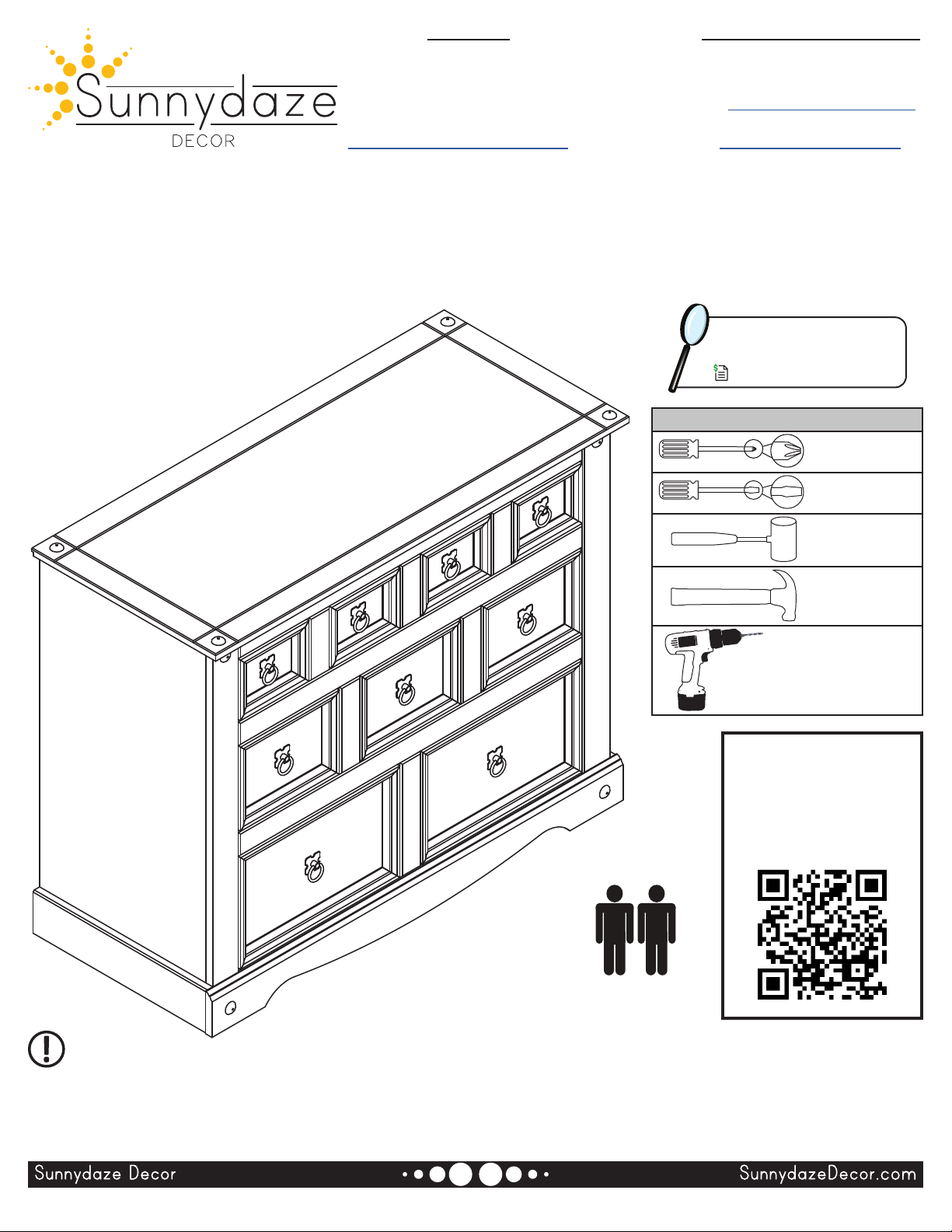
Instrucciones
Instructions
Read the manual carefully to ensure you fully understand
all use, care, assembly, and safety information.
Read this manual carefully and
follow the assembly instructions
in the order listed. Pay close
attention to assembly drawings.
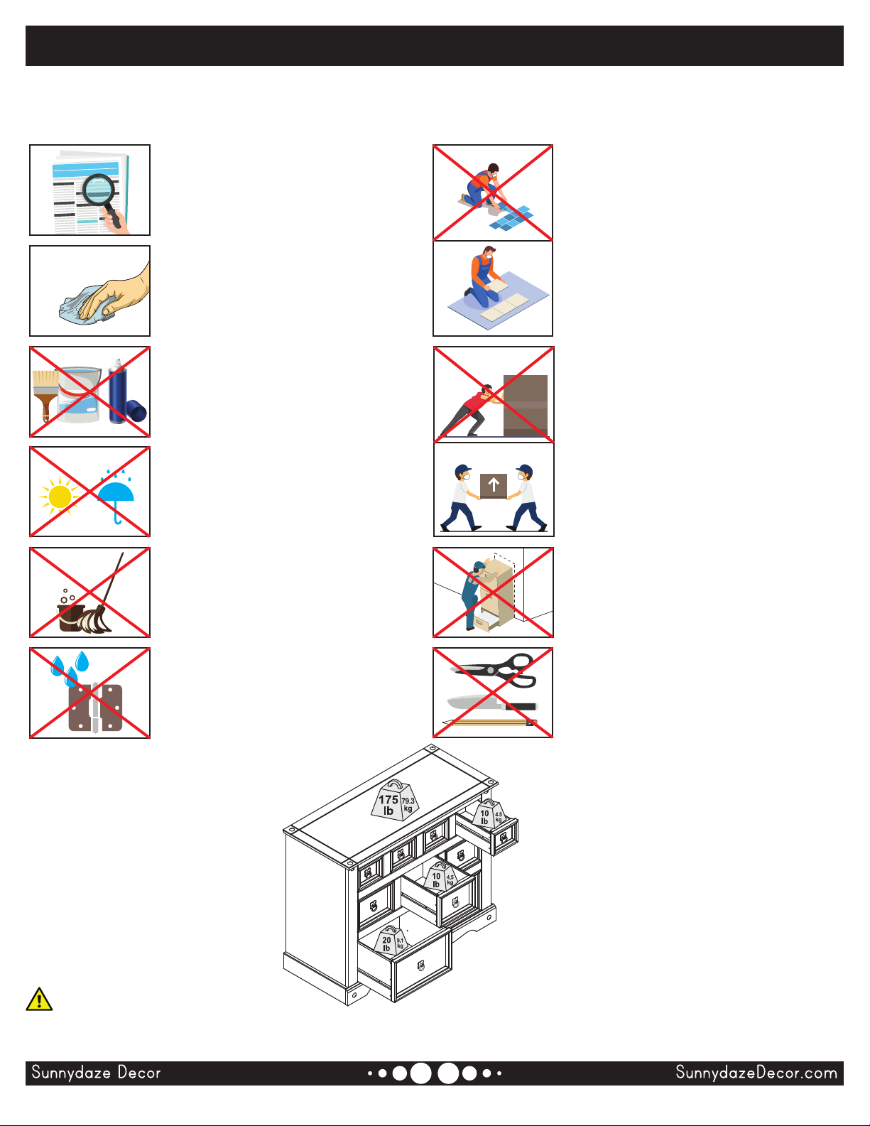
Regularly clean with a clean
microber cloth to prevent dust
accumulation.
Do not paint the unit.
Do not use abrasive materials or
cleaners to clean the furniture.
Indoor use only.
Do not expose the furniture to
heat or humidity.
When cleaning nearby the
furniture, do not allow contact
with water or cleaners as it may
deteriorate the furniture.
Do not allow metal components
to come in contact with water or
cleaners as it may cause rust and
staining.
Assemble on a soft, at, clean, and
dry surface.
Use a soft, protective barrier when
assembling the furniture.
TIP: Use the box carton as a
protective layer to separate and
protect the parts from scratches and
other damage during assembly.
Do not push or drag furniture as
doing so may damage the unit.
Only move furniture when it is empty.
Always ask for help when moving
furniture.
Avoid Accidents - Do not climb, sit
or stand on the furniture.
Do not allow children to play on or
inside the furniture.
Keep sharp objects away as they
may scratch or damage the unit.
Do not use the furniture as a writing
surface without a padded barrier.
Page 2 / 17
WARNING:
Manufacturer and seller expressly disclaim any and all liability from personal injury, property damage or loss, whether direct or