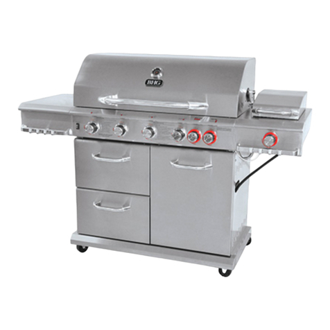
Sunshine HORIZON 4600 Installation instructions

Ver.2.0
CE845
Made In China For
ARLEC BARBEQUES PTY LTD
274 Maroondah Hwy
Mooroolbark, VIC 3138
Australia
!" #$
%!&$$'! (!&
!!! !)%!'
Retain These Instructions For Future Use

2
SAFETY PRECAUTION
•This grill is designed for outdoor use only THIS APPLIANCE SHALL
NOT BE INSTALLED OR USED INDOORS.
•The area surrounding your new grill should be kept clean, and free
from flammable liquids and other combustible materials such as
mops, rags, brooms, as well as solvents, cleaning fluids, and gasoline.
•Never locate this appliance in an enclosed room or under sealed
overhead structure or any type of enclosed area such as a garage,
shed, or breezeway. Keep clear of trees and shrubs.
•Never let clothing, potholders or other flammable materials come in
contact with or close to any grate, burner or hot surface until it has
cooled. Fabric may ignite and result in personal injury. Certain
materials or items, when stored under or near the appliance, will be
subjected to radiant heat and could be seriously damaged.
•BURNERS: Check to ensure no insects or blocking the venture tubes.
Use a special venture brush to clean. Use a pin or a toothpick to clean
the orifice on the gas valve. DO NOT ENLARGE THE HOLE.
SAFETY INSTRUCTION
•FOR OUTDOOR USE ONLY.
•READ THE INSTRUCTIONS BEFORE USING THE APPLIANCE.
•WARNING! : ACCESSIBLE PARTS MAY BE VERY HOT. KEEP
YOUNG CHILDREN AWAY. This appliance gets very hot. Take
special care when children or elderly people are present. Particular
care must be taken when removing the drip tray. Hot fat causes
severe injuries.
•DO NOT MOVE THE APPLIANCE DURING USE.
•TURN OFF THE GAS SUPPLY AT THE GAS CYLINDER AFTER
USE. Turn off all burner controls valves after use.
•ANY MODIFICATION TO THE APPLIANCE MAY BE DANGEROUS.

3
•THIS APPLIANCE SHALL BE KEPT AWAY FROM FLAMMABLE
MATERIALS. There should be no combustible materials less than
600 mm from the sides of barbecue and less than 1500 mm above the
cooking surface of the barbecue.
•Protective gloves should be worn if hot parts or utensils are to be
handled.
•People with flammable clothing such as nylon should keep well away
from the barbecue when alight.
•DO NOT allow unburned gas to build up.
•In the event of gas leak, TURN OFF GAS SUPPLY AT THE
CYLINDER.
•In the event of fat fire, DO NOT DOUSE WITH WATER. Turn off gas
supply at the cylinder.
•Every time the cylinder is reconnected, do a leak test.
•Never leave burners on high for more than 10 minutes unless cooking.
NATIONAL AUTHORITY REQUIREMENTS
All gas fitting work, service and repairs (including works on any part of
the gas circuit) can only be performed by an authorized gas fitter in
accordance with national regulations. All replacement parts must meet
Sunshine specification.
GAS TYPES
The barbecues are both category I3+(28-30/37) and I3B/P(30) appliances.
Gas consumption, inlet pressure and injector orifice sizes are shown in the
following tables.
HZ46 HZ47 Side Burner
Gas LPG LPG LPG
Inlet Pressure (mbar) 28 28 28
Heat Input (kW) 14 14 3
Injector Orifice (mm) 1.00 1.00 0.92
Gas Rate (g/h) 1020 1020 219
Note: The size of the injector orifice is stamped on one of the hexagon faces (eg:
“100” for 1.00 mm injector). LPG = Butane or Propane gas, propane is
recommended for use all year round. Butane for warmer climates/summer only.

4
ASSEMBLY INSTRUCTION
Inspect all components for damage before assembly begins. If damage is
present please contact your local dealer. Replace the damaged components
with original manufacturers’ parts only.
The cart panel, door, condiment assembly and main BBQ body have been pre
assembled for convenience and ease of assembly. Some assembly will be
required to complete this unit.
Assemble the barbecue trolley following steps as indicated below.
NB: some models have a round hole in the base for small gas bottles. In UK/Europe regulations
prohibit the use of gas bottles inside the BBQ cabinet, please locate bottle outside. The internal
hole can be used as a storage/rubbish bin and will fit standard bucket type bins.
Step 1
Assemble bottom shelf with trolley left hand
panel by sliding the front and rear legs of
panel onto the front and rear legs of bottom
shelf as illustrated.
Note : Make sure the black plastic inserts are
located on the left side facing down and the
door latches are facing the front. No screw
required for this step
Step 2
Install the trolley right hand panel on the
opposite side of the bottom shelf with the
same procedure.
Note : No screw required for this step
Step 3
Remove castor from the packaging and place
lockable castor on LH leg assembly and fixed
castor on RH leg assembly under the bottom
shelf. To secure lockable castor, make sure
the lockable castor is in lock position. Screw
castor into the black plastic inserts and hand
tight. Release brake when finished.
Note : No screw required for this step

5
Step 4
Attach the horizontal support rail to the front
legs. Then align the holes on both ends of the
support rail with the threaded holes on the
legs. Tighten with two M5 screws.
Step 5
Insert four M5 screws into the LH and RH
rear legs with hand tighten. Make sure to
loosen the screws to slide in the rear panel.
Step 6
Attach rear panel between RH and LH rear
leg. Align the slots on the rear panel on the
srews and push with a gentle downward
pressure as illustrated. Tighten all four
screws.
Step 7
Place door assembly in front of LH cart
assembly, ensure that the door handle are on
top position. Slide the bracket located at the
back of door assembly onto the LH stud on
the front of the trolley left hand panel as
illustrated.

6
Step 8
Place condiment shelf assembly in front of
the trolley right hand panel, ensure that the
condiment shelf handle are on top position.
Slide the bracket located at the back of
condiment shelf assembly onto the RH stud
on trolley right hand panel as illustrated.
Step 9
Place front trimming infront of RH and LH
trolley assembly. Align bolt holes located on
the inside RH/LH trolley assembly and secure
using four M5 long bolts.
Step 10
Attach LH side shelf assembly to LH trolley
assembly, slide LH side table assembly onto
front/rear legs of the L/H frame with
downward pressure as shown. Secure with
three bolts and nuts. Make sure the table is
slotted in equally during assembly.
NB: Different models come with different side shelf
units. These units may (or may not) include
side burner, marinating bowl, ice chest/sink or
lid.

7
Step 11
Attach RH side burner assembly to RH cart
assembly, slide RH side burner assembly
onto front/rear legs of the RH frame with
downward pressure as shown. Tighten with 2
bolts and nuts only to the outsides holes only.
Step 12
Attached cylinder hook under RH panel bar. Align the hole and secure with
bolt and nut.
Step 13
Remove bbq body assembly from the
packaging and take out grill plate, hot plate,
warming rack, flame tamer and all
accessories inside the bbq to reduce weight.
Lift the bbq body over the trolley assembly
and carefully lower onto the trolley until the
BBQ body rests on the upper side section of
side shelf.

8
Step 14
Place the grill plate flame tamers on right
lower level of bbq body assembly directly
above burners between the location tabs on
the bbq chassis.
Step 15
Insert the warming rack and place cast iron
grill plate directly above flame tamers and hot
plate on support ribs as illustrated.
Step 15
Slide the drip tray on bottom of barbecue
body as illustrated. Make sure the drip tray is
seated properly inside the location tabs. The
drip container fits under the drip tray run off
hole.
Assembly of the barbecue is complete.
Please read all cautions and warnings before
using your barbecue

9
LIGHT
Every HORIZON BBQ has been equipped with tested LED located inside the
hood handle. The LED provided, produces a unique light effect in forward
direction for convenience at night time. The battery compartment is located on
the left hand side of handle.
To install the batteries, unscrew counter clockwise the battery compartment
from handle as indicated in Figure below. The battery compartment houses
three size “C” batteries. Check for correct polarity alignment as indicated in the
battery compartment. Once batteries are installed, replace the battery
compartment. Turning it clockwise until it stops.
CAUTION! Do Not Over Tighten, and do not use battery compartment to lift
hood.
CAUTION!
•There are no user serviceable parts for this LED unit. Do not attempt any
repairs yourself, doing so will void the manufactures warranty. In the
unlikely event, your unit may require service. Please contact your nearest
Arlec Sunshine Barbecue dealer.
•Do not modify the circuit. This circuit is already optimized and confirmed
by tests and by measurements.
GAS SUPPLY CYLINDER
LP gas cylinders used with this appliance must have a cylinder capacity of at
LEAST 6 kg if propane or 13 kg if Butane.
GAS REGULATOR
A gas regulator conforming to the national standard must be fitted to the gas
cylinder to provide the appropriate gas pressure.
WARNING! : NEVER ATTEMPT TO OPEN OR ADJUST THE REGULATOR
Consult your gas dealer if you think the regulator is not working properly.

10
SUPPLY HOSE
A hose conforming to the national standard must be connected at one end to
the regulator outlet and at the other to the barbecue inlet nipple using hose
clips. The hose length must not exceed 1.5 m.
CONNECTING THE GAS SUPPLY
1. Screw the female flared fitting of the hose and regulator onto the bbq
inlet fitting at one side and side burner inlet fitting on the other side,
tighten using two adjustable wrenches. These fittings should be
tightened in a clockwise direction. Be sure that the connection is tight
(do not over tighten).
Ensure that all connecting threads and surfaces
are undamaged, clean and free from oil and dirt.
When fitting the hose, ensure that it is free from torsional (twisting)
stress, kinks or sharp bends. Protect the hose from dripping grease
and do not allow it to touch any hot surfaces, or sharp edge.
2. Attach the regulator to the gas cylinder. Refer to the instructions
supplied with the regulator for details regarding fitting.
3. Test for gas leak. Do a test leak each time the cylinder is installed,
whether it has been refilled or not. Check all other joints at least once
a year. If the hose shows deterioration or damage, leak test the entire
outer surface while under pressure. Replace at first sign of leak or age
cracking. Remember to turn the cylinder valve OFF before removing
hose.
CHECKING FOR LEAKS
Turn the gas on at the cylinder, or make sure gas is
available to the barbecue, but do not turn the burners on.
This fills the gas lines with gas. Now brush or pour some
soapy water onto all connections. If there Is a leak.
bubbles should appear within about 20 seconds. If you

11
find any leaks, tighten the connection. If the leaks persist, contact an
authorized agent.
DO NOT USE NAKED FLAME FOR LOCATING GAS LEAKS.
IF A LEAK PERSIST, CALL AN AUTHORISED GAS FITTER. DO NOT USE
APPLIANCE UNTILL ALL LEAKS ARE CORRECTED.
LIGHTING INSTRUCTIONS
Please read the SAFETY PRECAUTIONS section in this manual before you
start the unit for the first time or when the gas supply has been turned off or
when ever the gas cylinder has been changed. Make sure the orifices,
venturis, and main burners are free from obstructions. Perform a gas leak
check as described on this manual.
Before lighting ,
•Make sure the cylinder is filled.
•Make sure the gas is turned on at the cylinder, or that gas is available
to the barbecue.
•Make sure all gas connections are securely tightened.
•Open the BBQ hood/lid.
IGNITION:
1. The unit is equipped with a automatic ignition system that will ignite
each burner with a flame thrower type ignitor.
2. Ensure that all burner control knobs are in the “OFF” position.
3. Push in the gas control knob and turn counter clockwise to the high
flame setting. To light other burners repeat the process.
4. Ensure that the burner is lit and check the flame for proper
appearance and operation.
IF THE BURNERS DO NOT IGNITE, turn gas knobs to the “OFF” position and
wait 5 minutes to clear any gas that could have accumulated in and around
the barbecue.
MANUAL IGNITION:
In an unlikely event that all the automatic igniter does not work, place a long
lighted match through a hole located on the side towards the back of bbq.
Keep your hand below the bottom of the burner while doing this. Now turn the
gas control of desired burner to HI position. If any one burner can be lit, the
rest of the burners can be lit by crossing over. The burner to be lit must be
adjacent to the one that is already lit.

12
TEMPERATURE SETTING:
The temperature settings on this barbecue are labeled high (or ON) to low
flame and the control knob can be set any where in this temperature range on
all burners. To pre-heat this unit, close the lid and monitor the thermometer
located on the lid. Once pre-heated open lid to avoid overheating, unless
roasting.
CLEANING AND MAINTAINANCE
The HORIZON gas barbecue is designed to withstand the high temperatures
under normal operating conditions. Never scrape or scratch the hot painted
surfaces. Never dose the hot surfaces with water. If there is any excess fat or
grease, it is best removed while the barbecue is still warm.
COOKING SURFACES: The cooking grills have been porcelain enameled for
durability and ease of cleaning. These grills may be cleaned with a normal
NON abrasive household cleaning solution designed for kitchen use.
PORCELAIN ENAMEL CASTINGS: Periodic cleaning with a dry or damp
cloth or soft brush will keep porcelain enamel surfaces looking new. To clean,
soak in warm water and use only a kitchen appliance cleaner or a polish
designed for use on porcelain enamel surfaces.
DO NOT USE ABRASIVE CLEANERS ON THE PORCELAIN ENAMEL
FINISHES AS THIS WILL PERMANENTLY SCRATCH THESE SURFACES
BURNERS: Periodically inspect the burners blockage or corrosion. These can
be cleaned with a small piece of wire and a wire brush. Ensure that the
aeration screw is secure and that it is set properly.
HOSE: If the hose shows signs of deterioration or damage, use a soap water
solution to test the entire outer surface of the hose while under pressure
checking for bubbles, (this would indicate a leak in the hose). Replace the
hose at the first sign of a leak or if age cracking becomes apparent.
Remember to turn the gas off before removing the hose.
Off is
straight up
To ignite,
push the
knob in and
turn counter
clockwise
Keep turning
to reach the
low position

13
INJECTORS / MAIN BURNER ORIFICES: Injectors should be inspected on a
regular basis to ensure they are not blocked. Cleaning can be performed on
these injectors by removing the injector from the valve assembly. Using a very
small wire or a small pipe cleaner could also be used.
STAINLESS STEEL PANELS: Stainless steel is a very durable material and
should last indefinitely with minimal care. Due to the nature of the brushed
surface minor scratches and discoloration could appear with normal use and
handling. These scratches can be removed with the use of a medium or fine
grade polishing pad. Apply even gentle pressure and always rub with the grain
of the steel. DO NOT rub against the grain as damage could result. DO NOT
use steel wool as pieces will be left behind and these pieces will rust.
CARE OF STAINLESS STEEL PANEL:
Stainless steel is a highly preferred material in the residential and commercial
industries due to its strength, ability to resist corrosion and its ease of
cleaning. Stainless steel is often taken for granted and assumed to be
indestructible. However, care must be taken to ensure long life in your
Stainless Steel barbecue panel. To maintain the original appearance of your
HORIZON barbecue, a regular routine must be followed.
DO NOT:
Use wire wool pads, scrappers, harsh abrasive, scoring materials, bleaches,
or harsh cleaners on your Horizon BBQ stainless steel panel, or allow salt and
vinegar mixtures to remain in contact for a long period of time. This will cause
scratching, scoring, corrosion and pitting of your product. This component is of
non-rusting and non-magnetic stainless steel. There are many types of
stainless steel cleaners on the market today. We recommend that you clean
the external and internal stainless steel components with a cleaner that is
approved for #304 stainless steel and only clean when the grill is cool and in
indirect light. Never use steel wool to clean your grill and never clean the grill
when it is hot. Be especially careful when cleaning the Highlighted (shinny)
areas or your grill. Only clean these areas when absolutely necessary.

14
TROUBLE SHOOTING
PROBLEM POSSIBLE CAUSE SOLUTION
IGNITER
DOES NOT
SPARK
Electrode fouled
Electrode improperly
gapped
Electrode cracked
Lead wire is disconnected
Lead wire is cracked
No spark
Wipe the electrode with a soft clean
cloth.
The electrode should be 3 mm to 5 mm
away from the burner tube and if the
positioned close to the gas ports.
Gently bend the electrode tip into
position. (BE CAREFUL NOT TO
BREAK THE CERAMIC INSULATOR)
If the ceramic insulator on the electrode
is cracked it may short out, Replace the
electrode.
Check to ensure that all leads are
connected to the spark box and to the
electrode.
Split insulation on the wire could cause
the igniter to short out. Replace the wire
lead.
Remove plate and visually check
ignition box for a spark. If there is no
spark, contact authorized service agent.
BURNERS
WILL NOT
LIGHT
Gas supply turned off
Out of LPG
Blockage in gas system
Misarranged burner tube
on to the main orifice.
Improper gas line or
propane hose connection
Turn the fuel supply ON and try again
Detect the flow of gas by sound or smell
for gas being omitted. Allow gas to clear
before trying to re-light.
Check to ensure no insects or blocking
the venture tubes. Use a special
venture brush to clean.
Check under the flame deflectors to
ensure that the burner is properly
installed the main orifices.
Tighten the gas connection at the LPG
tank, HAND TIGHTEN ONLY.
UNIT WILL
NOT STAY
LIT
Wind
Running out of fuel
Try to shelter your gas grill from strong
winds. DO NOT USE IN ENCLOSED
AREAS.
Detect the flow of gas by smell or by
listening for the hiss of gas being
omitted.

15
UNEVEN
BURN
PATTERN
OR
FLASH
BACK
Blockage in the burner or
gas system
Corroded burner
Check to ensure no insects or blocking
the venture tubes. Use a special
venture brush to clean.
Use a pin or a toothpick to clean the
orifice on the gas valve. DO NOT
ENLARGE THE HOLE.
Corrosion of the burner can cause the
solid material between gas ports to
deteriorate resulting in uneven burning.
See your HORIZON dealer for
replacement burner tube.
EXCESSIVE
YELLOW
FLAME
Improper air adjustment Your HORIZON should burn with mostly
a blue flame. If the flame is mostly
yellow adjust the opening on the air
shutter on the burner tube. Open the air
shutter.
FLARE UPS
Excessive fatty foods
Grease build up
Trim all excess fat from meat before
cooking
Ensure that the flame deflectors are
clean of excess grease and that they
are located in the correct location.
Remove any excess grease from the
burn chamber.

16
PARTS IDENTIFICATION
NB: Item 17a or 17b varies depending on BBQ model

17
REPLACEMENT PARTS
Note : Use only original parts. This will protect your warranty coverage for
parts replaced under warranty.
Parts Under Warranty
Contact authorized dealer from whom you purchased this product, call
Sunshine Lifestyle Products Ltd for referral information.
European Distributor:
Sunshine Lifestyle Products Ltd
Unit 9, Oxonian Park
Langford Locks
Kidlington, Oxfordshire
England, OX5 1FP
Tel: +44 845 456 5111
Fax: +44 845 456 5122
e-mail: admin@sunlifestyle.com
www.sunshinebbq.co.uk
This manual suits for next models
1
Table of contents
Other Sunshine Grill manuals