aleo solar GmbH | Marius-Eriksen-Straße 1 | 17291 Prenzlau | Germany | info@aleo-solar.com
Quick Reference Manual Rel. 4.7, 08/2020, EN
Page 10/20
9.5 Parallel and serial connection
PV modules of the same type can be connected in parallel.
The PV modules in this series are fundamentally designed
for series connection.
• Only use PV modules of the same type and output
for parallel connection. Take measures for over-
current protection (e.g. line fuses) if necessary. Never
exceed the specified reverse current loadability of
the PV modules. Maximum number of module strings
that are allowed to be switched in parallel: 2 (fuse
rating / (short-circuit current x1.25)+1)
• Make sure that only PV modules with the same
amperage (Impp) are interconnected for series con-
nection and make sure that the voltages of strings
connected in parallel are the same. Even at low tem-
peratures, never exceed the maximum permissible
system voltage of the PV modules. Maximum number
of PV modules that are allowed to be switched in
series: maximum system voltage / (open circuit
voltage x 1.25), with respect to the temperature
coefficient.
• Make sure that the number and connection of the
PV modules match the electrical values specified by
the devices connected to the photovoltaic system.
• Make sure that the polarity is correct.
10 Details of mechanical mounting
10.1 Aligning the mounting profiles
10.1.1 Permissible alignment
Fig.3 Permissible alignment of mounting profiles
a, b: Parallel profiles for mounting; c: Parallel, aligned
fingers of a mounting system.
10.1.2 Impermissible alignment
Fig.4 Impermissible alignment of mounting profiles
a: Profiles not parallel to one another;
b: Profiles neither parallel nor perpendicular to the
module edges;
c: The profile ends for the sides of a module are not
connected.
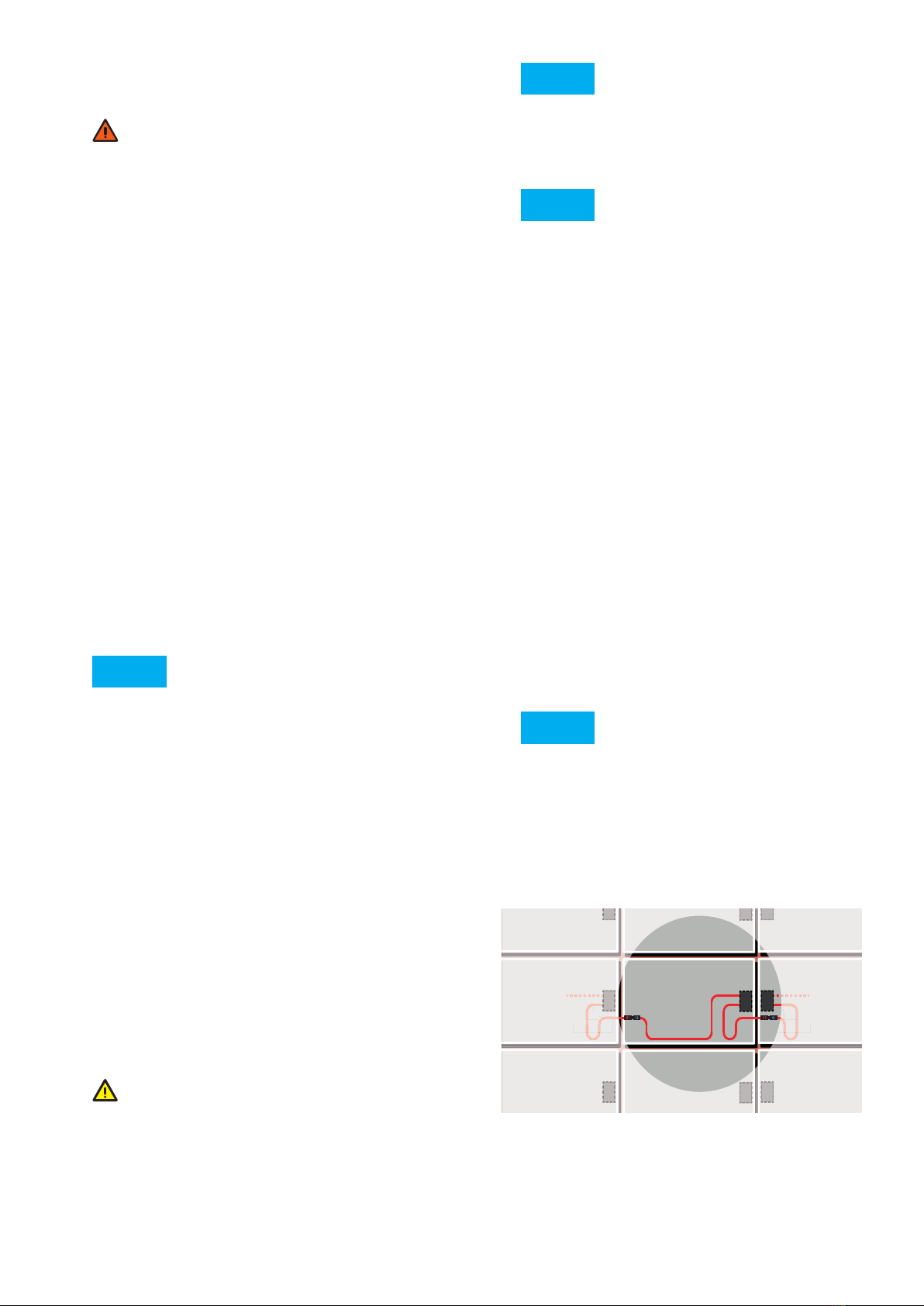
10.2 Clamp mounting for modules with standard
frames
Lay cables carefully to protect against damage from:
• Direct environmental factors, such as precipitation
• movement (e.g. from wind)
• Indirect environmental factors, e.g. snow or ice,
which slip down behind the modules, and
• Chaffing on the insulation due to the cable
moving (e.g. from wind or ice).
9.3 Potential equalisation (earthing) of module
frames
NOTE
• Local regulations may specify potential
equalisation (earthing).
• When earthing the module frame, establish a safe
electrical connection to the earth potential or
earthed sub-structure.
• Observe the requirements and recommendations
of the inverter manufacturer, as well as insurance
policies.
• The module frames are made of aluminium. When
mounting onto other materials, take suitable
measures to prevent electric corrosion, e.g. by
using a coating.
NOTE
Potential equalization does not serve as lightning
protection. Lightning protection may be necessary
in addition to potential equalization.
9.4 Lightning protection
WARNING!
Absence of or inadequate lightning protection.
Risk of fire or electric shock!
• Leave the planning and installation of the external,
and if required internal, lightning protection to be
carried out by qualified technicians at all times.
• It is essential to integrate an arrestor for
connecting the lightning rod with the lightning
protection. This ensures the safety and reliability
of the lightning protection as well as the
photovoltaic system.
• Do not under any circumstances include the
module frame or its earth as an active part of the
lightning protection (e.g. as a lightning arrestor).
_______________________________________________
NOTE
If you earth the module frame, the only task of this
earth is the potential equalisation between the
module frame and the supporting structure.
aleo solar GmbH | Marius-Eriksen-Straße 1 | 17291 Prenzlau | Germany | [email protected] Page 10/19 Quick Reference Manual Rel. 3.0, 07/2014, en-GB-DE (1)
9.4 Lightning protection
WARNING!
Absence of or inadequate lightning protection.
Risk of fire or electric shock!
• Leave the planning and installation of the external,
and if required internal, lightning protection to be
carried out by qualified technicians at all times.
• It is essential to integrate an arrestor for connecting
the lightning rod with the lightning protection. This
ensures the safety and reliability of the lightning pro-
tection as well as the photovoltaic system.
• Do not under any circumstances include the module
frame or its earth as an active part of the lightning
protection (e.g. as a lightning arrestor).
NOTE
If you earth the module frame, the only task of this
earth is the potential equalisation between the mod-
ule frame and the supporting structure.
10 Details of mechanical mounting
10.1 Aligning the mounting profiles
10.1.1 Permissible alignment
Fig.3 Permissible alignment of mounting profiles
a, b: Parallel profiles for mounting; c: Parallel, aligned
fingers of a mounting system.
10.1.2 Impermissible alignment
Fig.4 Impermissible alignment of mounting profiles
a: Profiles not parallel to one another; b: Profiles neither par-
allel nor perpendicular to the module edges; c: The profile
ends for the sides of a module are not connected.
10.2 Clamp mounting for modules with standard
frames
10.2.1 Arranging the clamps
■ Permissible arrangement
Fig.5 55Permissible clamp arrangement for framed
modules
a: Symmetrical clamping on the long sides, b: Asymmetrical
clamping on the long sides (acceptable for certain load
levels), c: Symmetrical clamping on the short sides.
■ Impermissible arrangement
Fig.6 55Impermissible clamp arrangement for framed
modulesPermissible clamp arrangement for
framed modules
Impermissible clamp arrangement for framed modules
(1)a: Missing clamps, b, c: Clamping on both short and long
sides.
Fig.7 Impermissible clamp arrangement for framed
modules (2)
d: Protruding clamps, e: Opposing clamps have different
distances to the module corners, f: Asymmetrical clamps on
the short sides.
10.2.2 Clamp dimensions
Observe the following information for clamp lengths and
depths.
GID AS022b
a b c
GID AS023b
a b c
a b c
GID AS024a
GID AS025b
ab c
d e f
GID AS069b