Sunwoda Atrix 5 Series User manual

1
User Manual
Atrix 5/10/15/20 Series
Version:V1.0

2
Content
1Safety precaution......................................................... 3
1.1 Storage and installation environment............................... 3
1.2 Battery safety guidelines.......................................... 3
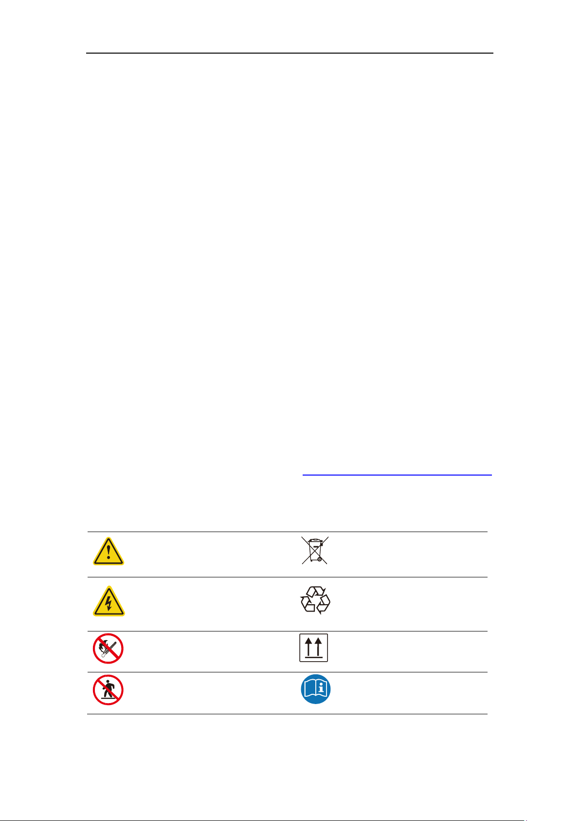
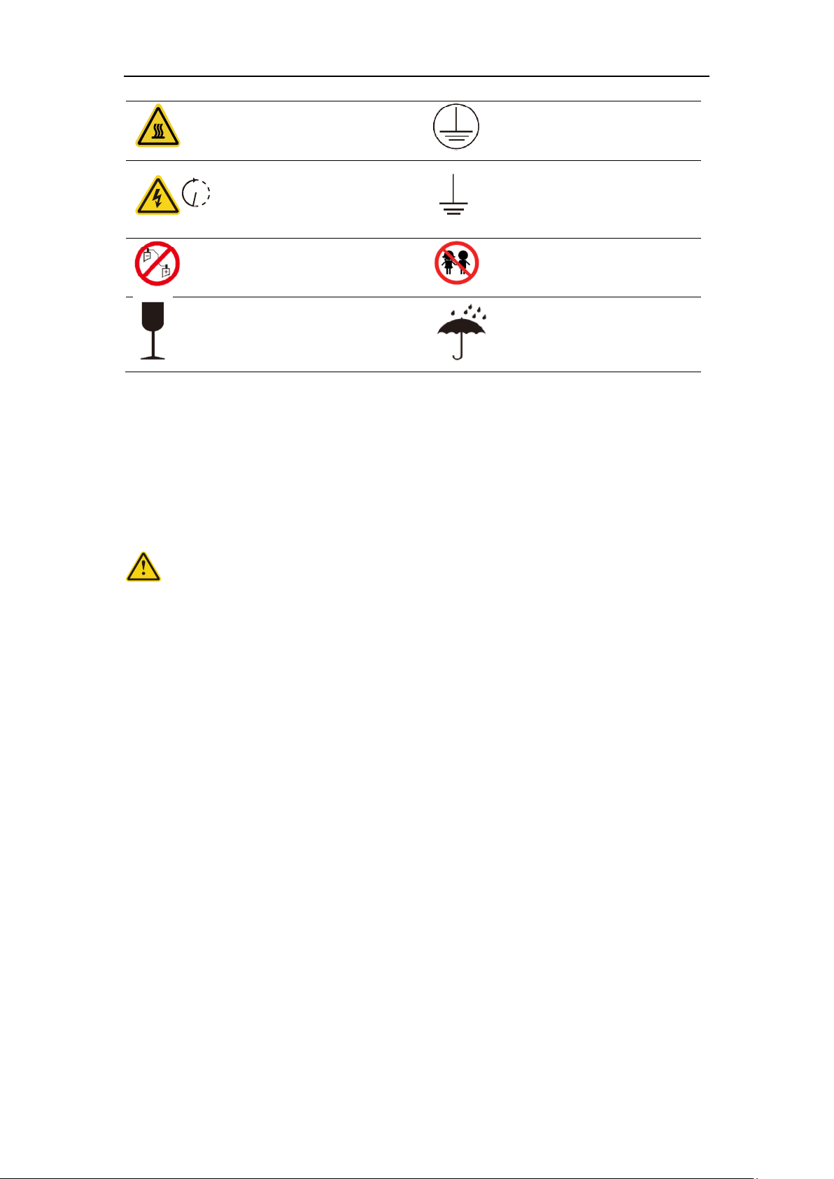
1.3 Warning signs and stickers......................................... 3
1.4 Emergency handling................................................. 4
1Product Description....................................................... 5
1.1 Product Introduction............................................... 5
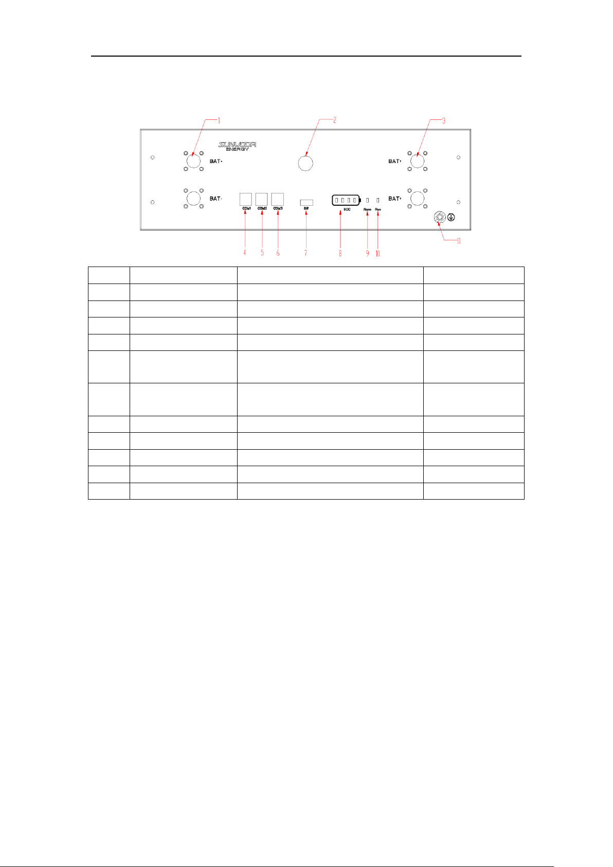
1.2 Product appearance description..................................... 6
2Installation Guide........................................................ 7
2.1 Installation site requirements..................................... 7
2.1.1 Environmental requirements................................... 7
2.1.2 Physical installation requirements........................... 8
2.1.3 Preparation of installation tools............................ 9
2.1.4 Unboxing guide............................................... 9
2.2 Installation steps................................................ 10
2.2.1 Installation step........................................... 10
3Electrical connection.................................................... 14
3.1 Grounding......................................................... 14
3.1.1 Connector installation...................................... 15
3.1.2 Guide of electrical connection.............................. 16
4System commissioning..................................................... 22
4.1 System power on................................................... 22
4.2 System power off.................................................. 23
4.3 System configuration.............................................. 23
5Maintenance and troubleshooting.......................................... 25
5.1 Routine maintenance............................................... 25
5.2 Fault checklist................................................... 26
6Warehouse storage guidelines............................................. 27
6.1 Packaging guidelines.............................................. 27
6.2 Storage........................................................... 28
7Dispose of used batteries................................................ 28
8Detailed parameter....................................................... 28
Battery module parameter................................................ 29

3
1Safety precaution
Read the manual carefully and operate in accordance with the safety precautions. Refer to local
safety regulations on items not covered in this manual. Electrical installation, maintenance must
be performed by professional / qualified personnel.
1.1 Storage and installation environment
Handle the product gently, prevent from dropping
Avoid open flame; keep away from flammables, explosives or corrosive chemicals
Choose cool and dry place for storage and installation
Prevent from water or humid intrusion
Prevent from accidental access (children and animals)
Do not step on the product packaging
Do not place any foreign objects on top of the battery pack
Do not store the battery pack upside down
1.2 Battery safety guidelines
Prevent from electrostatic discharge
Wear insulating gloves when handling batteries.
Do not energize auxiliary power during installation
Check the polarity carefully before switching on the system
Defected or damaged batteries shall not be charged or discharged
Use the product only with inverters authorized by Sunwoda, or consult Sunwoda's product
engineers. For compatible list inverters, please visit: https://www.sunwodaenergy.com/download.
1.3 Warning signs and stickers
Warning generic hazard
DO not mix with domestic
Warning
High Voltage -
Electrical shock hazard
Please recycle
No flame
This side up
No stepping on
User manual

4
Warning
High temperature
Protective Earth
(connector)
Warning
High Voltage
Wait 5 min till fully discharged
Protective Earth
(general identification)
Do not short circuit
(cut off power)
Keep away from children
Fragile
Do not get wet
1.4 Emergency handling
Wear personal protective equipment (PPE) such as goggle, facemask, insulated gloves and boots.
Evaluate the situation before taking remedy action. When it is safe to do so, disconnect external
AC or DC power connection.
Damaged or deformed battery enclosure
Risk of chemical leakage (i.e. electrolyte) and internal short-circuit.
Warning
Deformed or severely damaged battery pack can lead to piercing of cell pouch (chemical leakage)
or internal short-circuit (thermal runaway). The damaged battery pack can release toxic gas. Keep
away from it.
In case of accidental skin contact, wash the skin thoroughly with soap and seek medical advice. For
eye contact, wash under running water (~15 minutes) and require immediate medical attention.
Fire hazard
If the fire is not from the battery or not spread to the battery, use FM-200 or CO2 fire extinguisher
to put out the fire.
If the battery pack catches fire, do not attempt to put out the fire and evacuate immediately.
Seek medical in case of inhalation of pungent and toxic fumes.
Keep damaged batteries isolated and call your local fire department. Contact service for further
support.
Note:
1. If a fire occurs during battery charging, disconnect the battery pack circuit breaker and cut off
the power supply for charging under safe conditions.
2. If the battery string does not catch fire, extinguish the fire before the battery string catches fire.
3. If the battery pack catches fire, do not attempt to extinguish the fire. Evacuate immediately.
5 m in

5
Water damage
Risk of electric shock and internal short-circuit. In case of splash or water spillage, when it is safe
to do so, dry the product. If any part of the battery system is submerged, keep away from water.
Do not reuse the submerged battery. Contact a service for support.
1Product Description
This document mainly introduces the product, installation, commissioning, maintenance,
troubleshooting, packaging, and transportation of the Atrix energy storage system.
1.1 Product Introduction
• This product is a lithium battery energy storage system based on the chemical composition of
Lithium Iron Phosphate (LFP), and adopts a module parallel design.
• A single system consists of a data display box (optional) and multiple battery modules, and
supports up to 4 battery modules in parallel.
• The battery energy storage system can be used with the inverter, and the communication adopts
CAN or RS485.
• The system supports up to 2 single systems connected in parallel, which can be expanded to
40kWh.
• The battery management system provides data collection, status monitoring and control to
ensure safe and reliable operation of the system.
• The system adopts IP20 protection design to support indoor use.
System Diagram

6
1.2 Product appearance description
Product size chart:
The battery module size diagram and effect diagram are shown in the following figure:
Size: W*D*H=443*410*135 mm
Weight: 45kg
Figure 4.3 Dimensions of module
Figure 4.4 battery module diagram

7
Product Front Panel Definition:
NO
Item
Function
Note
1
.BAT-
Battery output negative interface
2
POWER
Battery module switch button
3
BAT+
Battery output positive interface
4
COM1
Communication interface with PCS
RS485&CAN
5
COM2
Automatic addressing and internal CAN
communication interface
6
COM3
Automatic addressing and internal CAN
communication interface
7
SW
One-key open interface
8
SOC
Battery module SOC indicator LED light
9
Alarm
Battery module fault LED light
10
Run
Battery module running LED light
11
PE
Battery module ground hole
2Installation Guide
2.1 Installation site requirements
2.1.1 Environmental requirements
a. Ambient temperature: -10℃~+50℃ (recommended: 10℃~35℃ or 50℉~95℉).
b. Ambient humidity: 10-95%.
c. Altitude <= 2000 meters.
d. For indoor installation
• Avoid direct sunlight
• Avoid rain and snow
• Avoid flood-prone locations
• Install under shed if possible
• 3 feet of clearance from doors, windows, driveways, or other batteries
• Keep away from heating equipment.

8
• Protection against corrosive chemicals
• Prevent water from spilling
e. Consider locations with ventilation fans, smoke, heat or combustible gas detectors.
Warning!
Use of Atrix outside of the temperature range may cause irreversible damage to it
Note: If Atrix is used below 10 degrees or above 40 degrees, the charging and discharging
current of Atrix may decrease.
2.1.2 Physical installation requirements
This simple bracket is optional. Assuming that the client has a cabinet or bracket designed to meet
the standard 19inch and 3U height installation, it is not necessary to choose this suggestion and
ignore the following installation methods.
a. Product installation dimensions
Atrix 5:
Atrix 10:
Atrix 15:
Atrix 20:
BATT
Indoor
BATT
Outdoor

9
b. Weight
2.1.3 Preparation of installation tools
Tools
Electric screwdriver
(M5 sleeve)
Wrench
Personal Protective Equipment
Safety gloves
safety shoes
2.1.4 Unboxing guide
Unpacking checklist
45kg (99.2lbs)
For 2 persons

10
Components
Battery
Data display box
(Optional
accessory
Feet
Racks
M5*10 screw
M6*14ground
Wiring Harness kit Packaging Components Between Battery module
Positive wire harness
X1
Negative wire harness
X1
PCS-RS485/CAN
communication cable
X1
Power on cable X1
System wiring harness kit Packaging Components
Positive wire harness X1
Negative wire harness X1
PCS-RS485/CAN
communication cable X1
2.2 Installation steps
2.2.1 Installation step
1)Feet racket installation
Take out the 4PCS feet and rackets to install.

11
2) Easy racket installation
Install simple rackets on both sides of the battery module (including simple rackets with feet)
3) Battery module installation
a. Lay the battery module with simple racket (including feet) on the horizontal floor (Adjust
feet to make the battery module horizontal if the floor is not flat).
b. Install other battery modules with simple racket one on one. Fix the structure with M5*10
screw after the stack-up.

12
c. A maximum of four battery module are stacked based on the system capacity.
4) Data display box installation (Optional)
Function and operation introduction of data display box:
1) Display control of LCD screen or segment code screen
2) Communication between battery and PCS
3) Remote operation, parameter set, software update
4) Compatible with multi series of rack type of product
5) Optional based on requirement of customer and system
Dimension and appearance of data display box
Dimension: Width*Depth*Height=250*200*35 mm

13
Figure 4.5 Dimension of data display box
Installation step
Take the rain cover and data display box, and as shown in the picture, paste a fixed data display
box on the top battery pack (with glue on the bottom).
Note: Neglect this step if data display box not bought

14
3Electrical connection
3.1 Grounding
Grounding point
Introduce the product ground point to the nearby ground point

15
3.1.1 Connector installation
Schematic diagram of power wiring
Connector installation instructions
The power cable connection is shown in the figure, press and hold the red unlock button, and there
is a clicking sound for the plug connection.
Battery pack
Connector base
Unlock button
Connector plug

16
3.1.2 Guide of electrical connection
Electrical connection for single module shown as follows, PCS: 51.2V input
No.
Electrical connection
Wire specifications
Mark
1
Battery module grounding
Non
With grounding terminal
2
Connect the battery negative with
PCS negative, typical color BLACK
1/0 AWG,2000mm
PCS- to BAT-
3
Connect the battery positive with
PCS positive, typical color ORANGE
1/0 AWG,2000mm
PCS+ to BAT+
4
Connect the battery with PCS-CAN,
typical color GRAY
8P8C Type 5 Shielded
network cable
BAT-CAN to PCS-CAN
5
Terminal Resistance
120Ω
/
—+
CAN
BAT- BAT+
PCS
Terminal
Resistance
2
3
4
1
5

17
One cluster of parallel connection shown as follows, PCS: 51.2V input
No.
Electrical connection
Wire specifications
Mark
1
Battery module grounding
Non
With grounding terminal
2
Connect the battery negative with
PCS negative, typical color BLACK
1/0 AWG,2000mm
PCS- to BAT-
3
Connect the battery positive with
PCS positive, typical color ORANGE
1/0 AWG,2000mm
PCS+ to BAT+
4
Connect the battery with PCS-CAN,
typical color GRAY
8P8C Type 5 Shielded
network cable,2000mm
BAT-CAN to PCS-CAN
5
Terminal Resistance
120Ω
/
6
Connection with one-button power
on function, paired connection
Power on cable,250mm
/
7
Negative wiring between battery
modules, typical color BLACK
1/0 AWG,320mm
BAT- to BAT-
接地
—+
CAN
BAT- BAT+
PCS
4
3
2
1
6
5
4
7
8
9

18
8
Positive wiring between battery
modules, typical color ORANGE
1/0 AWG,320mm
BAT+ to BAT+
9
Connect the battery with BAT-CAN,
typical color GRAY
8P8C Type 5 Shielded
network cable,220mm
BAT-CAN to BAT-CAN
One cluster of parallel connection with data display box shown as follows (Optional for data
display box), PCS: 51.2V input
No.
Electrical connection
Wire specifications
Mark
1
Battery module grounding
Non
With grounding terminal
2
Connect the battery negative with
PCS negative, typical color BLACK
1/0 AWG,2000mm
PCS- to BAT-
3
Connect the battery positive with
PCS positive, typical color ORANGE
1/0 AWG,2000mm
PCS+ to BAT+
接地
4
3
2
1
5
6
7
8
9

19
4
Connect the display box with PCS-
CAN, typical color GRAY
8P8C Type 5 Shielded
network cable,2000mm
BAT-CAN to PCS-CAN
(Display box)
5
Terminal Resistance
120Ω
/
6
Connection with one-button power
on function, paired connection
Power on cable,250mm
/
7
Negative wiring between battery
modules, typical color BLACK
1/0 AWG,320mm
BAT- to BAT-
8
Positive wiring between battery
modules, typical color ORANGE
1/0 AWG,320mm
BAT+ to BAT+
9
Connect the battery with BAT-CAN,
typical color GRAY
8P8C Type 5 Shielded
network cable,220mm
BAT-CAN to BAT-CAN
Two clusters of parallel connection shown as follows, PCS: 51.2V input
No.
Electrical connection
Wire specifications
Mark
1
Battery module grounding
Non
With grounding terminal
2
Connect the battery negative with
combiner box negative bus-bar,
1/0 AWG,2000mm
Bar-bus- to BAT-
—+
CAN
BAT- BAT+
PCS
5
2
(3)
4
1
10
6
11
12
Grounding
7
8
9

20
typical color BLACK
3
Connect the battery positive with
combiner box positive bus-bar,
typical color ORANGE
1/0 AWG,2000mm
PCS+ to BAT+
4
Connect the battery with PCS-
CAN, typical color GRAY
8P8C Type 5 Shielded
network cable,220mm
BAT-CAN to BAT-CAN
5
Terminal Resistance
120Ω
/
6
Connection with one-button
power on function, paired
connection
Power on cable,250mm
/
7
Negative wiring between battery
modules, typical color BLACK
1/0 AWG,320mm
BAT- to BAT-
8
Positive wiring between battery
modules, typical color ORANGE
1/0 AWG,320mm
BAT+ to BAT+
9
Connect the battery with BAT-
CAN, typical color GRAY
8P8C Type 5 Shielded
network cable,220mm
BAT-CAN to BAT-CAN
10
Combiner box
/
11
Connect the combiner box with
PCS negative, typical color BLACK
1/0 AWG,2000mm
BAT- to BAT-
12
Connect the combiner box with
PCS positive, typical color ORANGE
1/0 AWG,2000mm
BAT+ to BAT+
Two clusters of parallel connection with data display box shown as follows, (Optional for data
display box), PCS: 51.2V input
This manual suits for next models
3
Table of contents