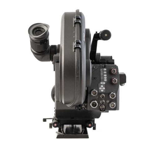
ARRI ICS-1 User manual

ICS-1 •SFHC-1
Instruction Manual
Singleframe Hand Control SFHC-1
Integrated Capping Shutter ICS-1
As of: November 26th 1998

EXPOSURE key
LED EXPOSURE
LED CAP CLOSE / OPEN
LED CAP Manual
CAP MANUAL key
SF OFF / ON switch
CAP MAN / AUTO switch
1/SEC / SEC switch
1x / INT switch
READY
LED
ICS-guide
slide-in mask
singleframe-
film recognition
module
light-tight cover
for pull-down
claw slits
Integrated Capping Shutter
control knob
hex-screw for
adjusting
locking grip
LED READY /
OPEN / CLOSE
socket for SFHC-1
cable to the
26 pin
camera-socket
SFHC-1
exposure time
interval time
HRS:MIN / MIN:SEC
INT. switch
BURST FRAMES

3
Contents
1. Contents
1. Contents 3
2. Safety Instructions 5
3. General Description 7
4. Modifying the ARRIFLEX 435
for Singleframe Takes 9
4.1 General ............................................. 9
4.2 Preparing the Film Gate ..................... 10
4.3 Attaching the Singleframe Film
Recognition Module........................... 12
4.4 Attaching the Integrated Capping Shutter .. 15
4.5 Attaching the Singleframe
Hand Control Unit SFHC-1 ................. 18
5. ARRIFLEX 435 in Normal Operation 21
6. Integrated Capping Shutter 23
6.1 Light-Tightness ................................... 23
6.2 Operating the Integrated Capping Shutter .. 25
7. Singleframe Hand Control Unit SFHC-127
7.1 Switching on Singleframe Operation ... 28
7.2 Recording Singleframes
(Photographic Mode) ......................... 29
7.3 Intervallometer Operation................... 32
7.4 Remote Operation ............................. 36
7.5 External Capping Shutter.................... 38
7.6 Light Control ..................................... 41
8. Indicators on the Camera Display 47
8.1 Configuring Mode 1
of the Camera Display ....................... 47
8.2 Framecounter .................................... 48
8.3 Burstcounter ...................................... 48
8.4 Interval Time ..................................... 49

5
Safety Specifications
2. Safety Instructions
Warnings
Note: Operational error possible!
Danger of injury or damage to the equipment!
General Safety Instructions
Attention! Danger of injury! Never
reach into the lens mount receptacle,
the interior of the camera or the ma-
gazine while the camera is running.
• To ensure safe, proper operation, please familiarise
yourself with this instruction manual.
• Assembly and initial operation should be carried out
by trained personnel only!
• Never run the camera without a lens or protective cap
on the lens mount receptacle!
• Never operate the movement locking mechanism while
the camera is running!
• Ensure that the camera is in a stable position!
• Remove the battery cable before transporting the camera!
• Remove the battery cable before carrying out maintenance
or cleaning!
• Repairs should only be carried out by authorised
service centers!
• Use only original ARRI spare parts and accessories!
Important Instructions
• In wet weather precautions must be taken to protect
electrical equipment.
• Avoid operational errors!
• Do not remove any screws which are secured with paint!

6
Safety Specifications
Product Specifications
In case of enquiries or when ordering, always state the
model and serial numbers.
Explanation of the Symbols
in this Instruction Manual
➪ photo indicates objects shown in the photographs.
Note on Compliance:
This product and the accessories recommended by the
manufacturer comply with the requirements of EU-
Guideline 89/336/EWG.

7
Introduction
3. General Description
System Overview
The system comprises the following components:
• The Singleframe Hand Control Unit SFHC-1 ➪ photo,
which facilitates setting all important parameters for
singleframe shots.
• The Integrated Capping Shutter (ICS), which ensures that
the camera is light-tight around the mirror shutter for a
period of approx. one hour for taking singleframe shots.
• The Singleframe Film Recognition Module ➪ photo,
which is used instead of the standard film recognition
module or the time code module to reduce the curvature
of the film loop.
• The Singleframe Software, which controls all singleframe
functions in the ARRIFLEX 435.
• The Slide-In Mask ➪ photo and the ICS-Guide ➪ photo
to modify the film gate.
• A light-tight cover ➪ photo for the pull-down claw
slits and the register-pin holes in the film gate.

8
26 pin socket
Installation

9
Installation
4. Modifying the ARRIFLEX 435
for Singleframe Takes
First, check that a 26-pin socket is visible on the right lower
side of the camera, as this is necessary for singleframe takes.
If there is no socket, the camera must be modified by an
authorised ARRI service center.
4.1 General
Due to the design of mirror-reflex film cameras, stray light
may pass around the mirror shutter onto the film when the
camera is not running. For normal film shots this is not a
problem, as the affected images fall into the camera run-
up, which is usually not used anyway. On singleframe shots
however, the stray light which during interval time can fall
onto the film around the mirror shutter can affect the quality
of the exposed singleframes.
The ARRI Integrated Capping Shutter covers the film during
the interval time with a thin metal plate. The metal plate is
pushed into the film gate after exposure. Before the next
exposure the plate is removed.

10
film
gate
locking
lever
Installation
film gate
movement
locking lever
knurled knob
filter
holder
format mask
film gate
shaft
4.2 Preparing
the Film Gate
To accomodate the movement of the pulldown claw during
film-transport, the film gate is designed with vertical slits
on both sides. Furthermore, there are two holes for the
register-pins. These openings must be covered to prevent
stray light from reaching the film.
To enable the shutter plate of the Integrated Capping Shutter
to slide into the film gate, a special guide is inserted into the
film gate in place of the filter holder. The plate then slides
into this ICS-Guide. Due to the form of the ICS-Guide it is
necessary to use special format masks.
• Before removing the film gate turn off the camera’s main
switch and remove the camera from the power supply.
• Turn the knurled knob ➪ photo until its marking
matches that on the movement block.
• Turn the movement locking lever ➪ photo to the “OPEN”
position. This will cause the movement block to swing
away from the film gate.

11
screws
film gate ICS-
format mask
cover
ICS-guide
modified
film gate
Installation
• Press the film gate locking lever ➪ photo towards the
magazine throat assembly and push the film gate ➪
photo towards the movement block, pressing lightly
on the lower end of the film gate ➪ photo and paying
attention that the film gate does not hit the movement
block.
• Grasp the film gate by the filter holder ➪ photo and
remove it by pulling upwards.
• Pull the filter holder sideways out of the film gate.
• Press the format mask ➪ photo on its side plate
backwards slightly and pull out of the film gate.
The filter holder and the format mask are held in position
by leaf springs. These leaf springs are each held by two
screws to the film gate.
• Entirely remove the screws holding the lower single
leaf spring, leaving the spring in place.
• Place the cover for the film gate openings over the
fastening holes of the leaf spring. The cover will
deform slightly. Then screw in the cover and the leaf
spring with the two screws.

12
Installation
• Slide the new singleframe format mask sideways into
the film gate ➪ photo (page 11).
• Slide the ICS-Guide ➪ photo (page 11) sideways into
the film gate.
• Check that the film gate and the film gate shaft are
free of dust and dirt.
• Grasp the film gate by the ICS guide and place it from
above onto the film gate shaft.
• Check that the film gate is placed correctly on its shaft.
• Press the lever towards the magazine throat assembly
and flip the film gate back into its correct position.
• Ensure that the lever swings back fully.
Note: The film gate can only be locked if the format
mask and filter holder are correctly inserted.
Swinging the movement block forwards when
the film gate is not correctly in place can cause
damage to the equipment!
4.3 Attaching the
Singleframe Film
Recognition Module
• The Singleframe Film Recognition Module is used
instead of the standard film recognition module or the
time code module to reduce the loop curvature.
On singleframe shots with the standard film end
recognition module or time code module, the
film curvature can cause unfocused images.
The Singleframe Film Recognition Module may
only be used up to max. 120 fps in normal
camera operation, as otherwise the camera may
switch off while running or damage the film.

13
fixing screws
screws
Installation
• Switch off the main camera switch and remove the
camera from the power supply.
• Remove the three screws from the magazine locking
cover ➪ photo.
• Remove the magazine locking cover.
• Hold the film recognition module tightly to prevent it
from falling onto the movement block and damaging
the module’s surface.
• Unscrew both fastening screws ➪ photo
.

14
TC- or film recognition
module
singleframe film recognition module
Installation
• Remove the film recognition module ➪ photo by
pulling it towards the movement block
.
When attaching the new module, ensure
correct plug positioning as otherwise damage
could be caused to the plug contacts!
• Attach the singleframe film recognition module ➪ photo
.
• Screw tight the two fastening screws ➪ photo (page 13).
• Replace the magazine locking cover and fasten with
the three screws ➪ photo (page 13).

15
screws
Installation
4.4 Attaching the
Integrated Capping
Shutter
To prevent stray light from falling on the film during the
interval time, the ARRI Integrated Capping Shutter covers the
film with a thin metal plate. After each exposure the metal
plate is pushed into the film gate and removed immediately
before the next exposure. The metal plate slides into the
ICS-Guide attached to the film gate. To ensure optimum
operation, the plate of the Capping Shutter must be aligned
with the ICS-Guide.
• Switch off the main camera switch and remove the
camera from the power supply.
• Open the camera door and remove the two fastening
screws ➪ photo. Any spacers between the hinge and
the camera housing should on inside the housing.
• Attach the Integrated Capping Shutter door by its hinge
to the camera housing and tighten slightly the two screws.
• Position the Integrated Capping Shutter door so that
there is an even gap to the housing and the door can
be correctly opened and closed.
• Tighten the two screws ➪ photo.
• Open the Integrated Capping Shutter door by approx.
30°and turn the door lock to the shut position.

16
hex screw
for
height adjustment
shutter platecontrol knob
ICS-guide
Installation
• Press the control knob ➪ photo on the Integrated
Capping Shutter and turn until the black plate reaches
the ICS-Guide.
Note: If the knob cannot be turned check if the door
lock is really in the shut position.
Do not use force to push the plate into the ICS-
Guide, as this could damage the plate or the guide.
• Check that the plate can be pushed into the ICS-Guide
easily and without catching. The height of the plate can
be set on the side of the ICS with the hex key ➪ photo.
Note: If the height of the plate is correctly set but it still
catches when being pushed in, the positioning
of the entire ICS door on the camera should be
re-checked.
• Check again that the plate slides into the ICS-Guide
easily and without catching.

17
door locked
26 pin socket
Installation
• Press the control knob of the Integrated Capping Shutter
and turn it until the black plate disappears in the ICS
door. Close and lock the ICS door.
To prevent inadvertent opening of the camera
door, it can only be opened when the Integrated
Capping Shutter is open.
• Press the control knob of the Integrated Capping Shutter
and turn. The plate will be pushed slowly into the ICS-
Guide. Pay attention to proper and smooth operation.
• Plug the cable of the Integrated Capping Shutter into
the 26-pin socket ➪ photo on the lower right side of
the camera and screw tight.

18
1x / INT switch
SF ON / OFF switch
Installation
4.5 Attaching the
Singleframe Hand
Control Unit SFHC-1
When attaching the Singleframe Hand Control,
damage can be caused to the shutter plate if it
does not slide into the ICS-Guide correctly.
Therefore check manually before attaching the
Singleframe Hand Control to see if the Capping
Shutter plate slides easily into the ICS-Guide
(see chapter Attaching the Integrated Capping
Shutter).
• Turn the SF or CAP switch ➪ photo to the OFF or
MAN position. Turn the 1x / INT switch ➪ photo to
the 1x position.
This switches off singleframe operation and the
Integrated Capping Shutter can later be operated by
the CAP-MANUAL key.

19
CAMERA socket
socket
Installation
• Plug the SF-C1-S cable into the socket marked CAMERA
➪ photo on the Singleframe Hand Control and the
Integrated Capping Shutter ➪ photo.
The LED next to the CAP-MANUAL key illuminates green.

20
This manual suits for next models
1
Table of contents
Other ARRI Camera Accessories manuals

ARRI
ARRI arrilux 400 lighthouse User manual

ARRI
ARRI IVS User manual

ARRI
ARRI SRH-3 Operating instructions

ARRI
ARRI SRH-3 User manual

ARRI
ARRI TRINITY 2 User manual

ARRI
ARRI LMB-6 User manual

ARRI
ARRI IVS User manual

ARRI
ARRI Hi-5 User manual

ARRI
ARRI ALEXA Mini LF SUP 7.1.2 How to use
ARRI
ARRI 535B User manual
Popular Camera Accessories manuals by other brands

Nikon
Nikon AF-S DX NIKKOR 16-85mm f/3.5-5.6G ED VR user manual

ZedCam
ZedCam WireFree Camera user manual

RIDGID
RIDGID SeekTech SR-20 operating instructions

SeaView
SeaView PM5FM38 installation instructions

Axis
Axis TP3201 installation guide

Hoppecke
Hoppecke 5 OPzV 250 Installation, commissioning and operating instructions