Sunwoda SunESS-5H Series User manual

User manual
SunESS-5H/10H/15H/20H series
Version:V1.0

Content
1 Safety precaution ...........................................................................................................................1
1.1 Storage and installation environment.................................................................................1
1.2 Battery safety guidelines.....................................................................................................1
1.3 Warning signs and stickers ..................................................................................................1
1.4 Emergency handling............................................................................................................2
2 Product description........................................................................................................................3
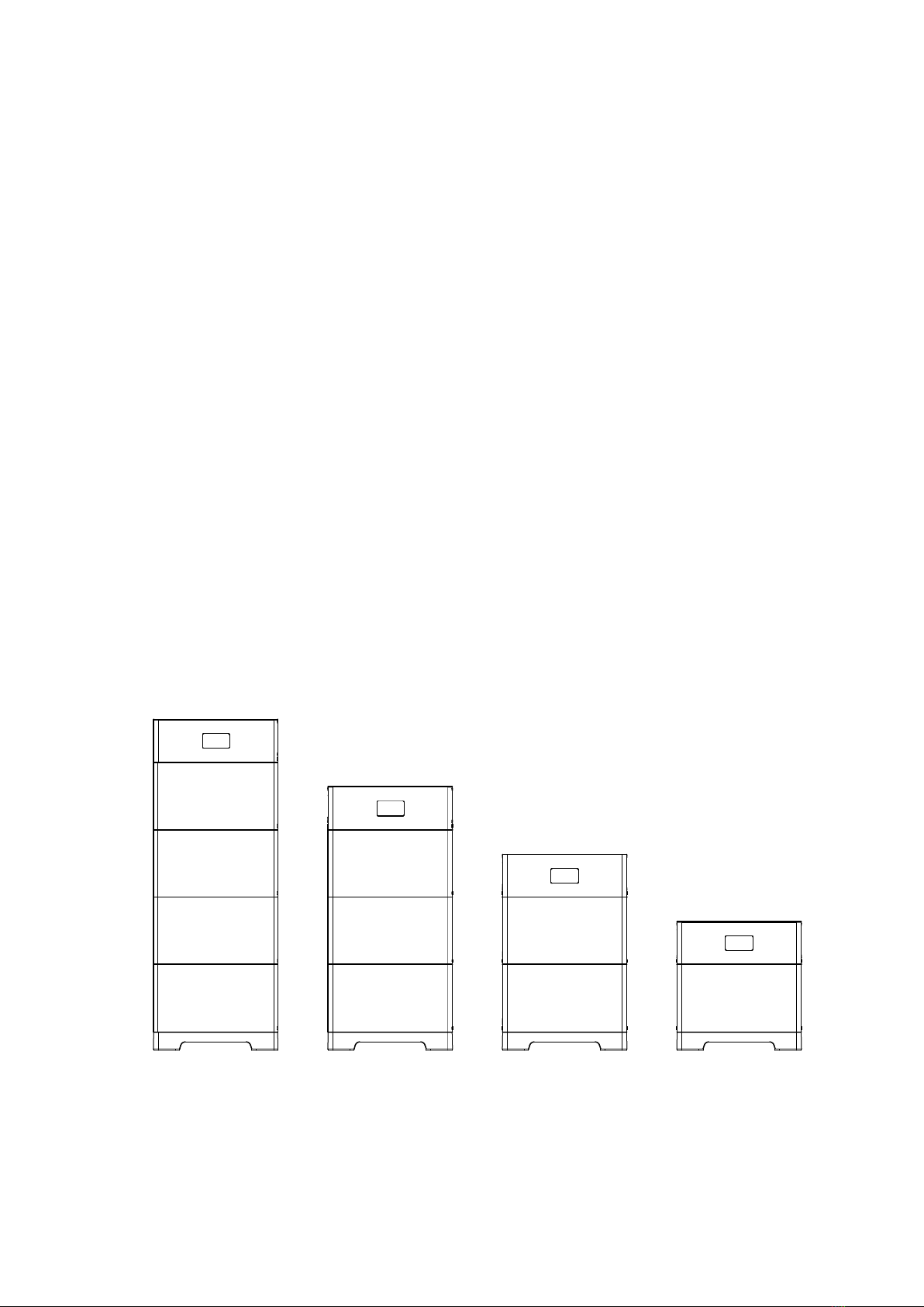
2.1 Product introduction...........................................................................................................3
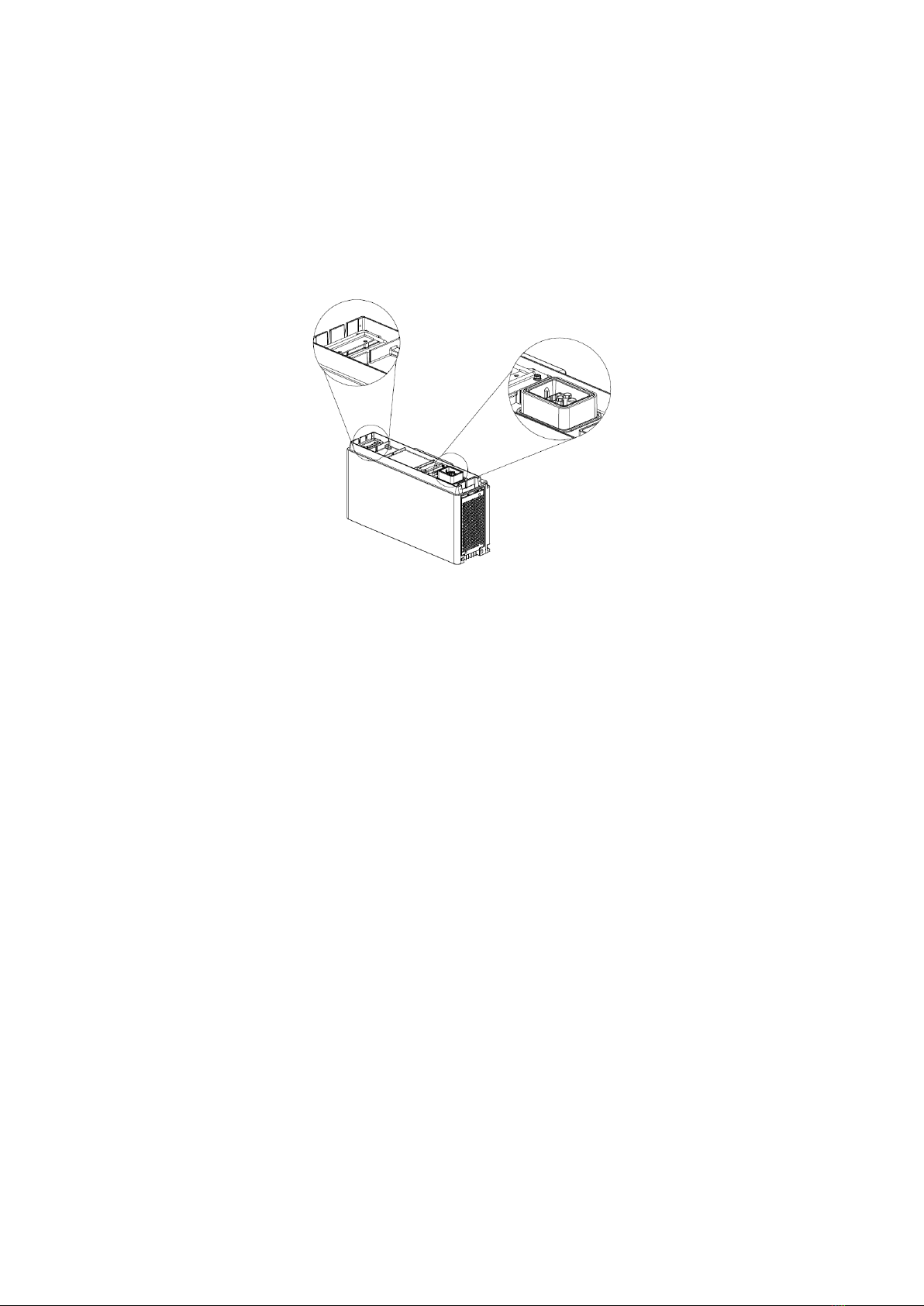
2.2 Appearance description ......................................................................................................5
3 Installation guide............................................................................................................................6
3.1 Environmental requirements ..............................................................................................6
3.2 Installation physical requirements ......................................................................................7
3.3 Installation...........................................................................................................................9
3.3.1 Installation tools.......................................................................................................9
3.3.2 Packaging components.............................................................................................9
3.4 Installation steps ...............................................................................................................11
4 Electrical connections ..................................................................................................................20
4.1 Grounding instructions......................................................................................................20
4.2 Power connector installation ............................................................................................21
4.3 Cable connection...............................................................................................................22
4.3.1 Single SunESS-H system..........................................................................................22
4.3.2 Multiple SunESS-H in parallel.................................................................................23
5 Power up your system..................................................................................................................24
5.1 System power up...............................................................................................................24
5.2 System power off ..............................................................................................................25
5.3 Display description............................................................................................................25
5.4 System configuration.........................................................................................................26
6 Maintenance and troubleshooting ..............................................................................................28
6.1 Routine maintenance........................................................................................................28
6.2 Fault checklist....................................................................................................................29
7 Warehouse storage guidelines.....................................................................................................31
7.1 Packaging guidelines .........................................................................................................31
7.2 Storage ..............................................................................................................................32
8 Dispose of used batteries.............................................................................................................32
9 Detailed specifications .................................................................................................................33

1
1Safety precaution
Read the manual carefully and operate in accordance with the safety precautions. Refer to local
safety regulations on items not covered in this manual. Electrical installation, maintenance must
be performed by professional / qualified personnel.
1.1 Storage and installation environment
Handle the product gently, prevent from dropping
Avoid open flame; keep away from flammables, explosives or corrosive chemicals
Choose cool and dry place for storage and installation
Prevent from water or humid intrusion
Prevent from accidental access (children and animals)
Do not step on the product packaging.
Do not place any foreign objects on top of the battery pack.
Do not store the battery pack upside down
1.2 Battery safety guidelines
Prevent from electrostatic discharge
Wear insulating gloves when handling batteries.
Do not energize auxiliary power during installation
Check the polarity carefully before switching on the system
Defected or damaged batteries shall not be charged or discharged.
1.3 Warning signs and stickers
Warning Generic hazard
DO not mix with domestic
Warning
High Voltage -
Electrical shock hazard
Please recycle
No flame
This side up
No stepping on
User manual
Warning
High temperature
Protective Earth
(connector)

2
Warning
High Voltage
Wait 5 min till fully discharged
Protective Earth
(general identification)
Do not short circuit
(cut off power)
Keep away from children
Fragile
Do not get wet
1.4 Emergency handling
Wear personal protective equipment (PPE) such as goggle, facemask, insulated gloves and boots.
Evaluate the situation before taking remedy action. When it is safe to do so, disconnect external
AC or DC power connection.
Damaged or deformed battery enclosure
Risk of chemical leakage (i.e. electrolyte) and internal short-circuit.
Warning
Deformed or severely damaged battery pack can lead to piercing of cell pouch (chemical leakage)
or internal short-circuit (thermal runaway). The damaged battery pack can release toxic gas. Keep
away from it.
In case of accidental skin contact, wash the skin thoroughly with soap and seek medical advice. For
eye contact, wash under running water (~15 minutes) and require immediate medical attention.
Fire hazard
If the fire is not from the battery or not spread to the battery, use FM-200 or CO2 fire extinguisher
to put out the fire.
If the battery pack catches fire, do not attempt to put out the fire and evacuate immediately.
Seek medical in case of inhalation of pungent and toxic fumes.
Keep damaged batteries isolated and call your local fire department. Contact service for further
support.
Water damage
Risk of electric shock and internal short-circuit. In case of splash or water spillage, when it is safe
to do so, dry the product. If any part of the battery system is submerged, keep away from water.
Do not reuse the submerged battery. Contact a service for support.
5 m in

3
2Product description
SunESS-H is a plug-in energy storage system. The battery module can convert high voltage direct
current (HVDC) into low voltage direct current (LVDC) through DC to DC conversion inside the
battery and stores the power in batteries, it can also convert LVDC into HVDC and send the power
to the grid through the inverter.
2.1 Product introduction
Residential energy storage system with lithium iron phosphate (LFP) technology
Modular design, single battery system with 5 to 20kWh (1 – 4 pcs battery)
Single battery module is equipped with DC to DC conversion, which increases the
output voltage to 350~450V
Supports power expansion, and the single battery system with power 2.5 to 10kW
Expandable to 60kWh (3 SunESS-H connected in parallel)
Support the mixing of new and old batteries.
Indoor or outdoor installation (IP65)
PCS communication interface: CAN or RS485
Bluetooth and WiFi for Mobile APP (PowerLite)
Advanced battery management system (BMS) provides data acquisition, status
monitoring and control to ensure the safe and reliable operation of the system.
Figure 2-1-1 SunESS-H configurations
5kWh
10kWh
15kWh
20kWh
PCS/INVERTER

4
Figure 2-1-2 System topology
WiFi Internet
GPRS
APP
APP
DC Power cable
Signal cable
Wireliss communication
Products within the dotted lineareprovided by SUNWODA ENERGY

5
2.2 Appearance description
Appearance of the whole system
Figure 2-2-1 Appearance of the whole machine
①Control module ② Battery module ③ Mounting the base
Control module
Figure 2-2-2 Left side of control module
①Power button ② DC breaker ③ Wi-Fi antenna ④ display
②
①
③
①
③
④
②
①
⑦
③
⑤
④
②
⑥
⑥

6
Figure 2-2-3 Right side of the control module
① Output Positive (DC+)
② Output Negative (DC-)
③ Parallel communication 0 (COM0)
④ Parallel communication 1 (COM1)
⑤ PCS communication (RS485/CAN)
⑥ Maintenance (LAN)
⑦ Protection earth (PE)
Battery module
Figure 2-2-4 Structure diagram of battery module
① Handle ② Power/communication connector
3Installation guide
3.1 Environmental requirements
a. Ambient temperature: -10℃~+50℃ (recommended: 10℃~35℃ or 50℉~95℉).
b. Ambient humidity: 10-95%.
c. Altitude < 4000m.
d. For outdoor installation
Avoid direct sunlight
Avoid rain and snow
Avoid location susceptible to flooding
Install under shed if possible
e. For indoor installation
3 feet clearance from doors, windows, driveway or other batteries
Keep away from heating device.
Prevent from corrosive chemicals
Prevent from water spillage
Consider location equipped with ventilation fans, smoke, heat, or flammable gas
detector
①
②

7
SunESS-H performance degrades when ambient temperature is below 10℃(50℉) or above
40℃(104℉) degrees.
3.2 Installation physical requirements
a. Item inspection

8
b. Installation clearance
c. Level control
d. L-bracket fixing bolt positioning
Take into account the actual surface condition before fixing the L-bracket: the bolt spacing is 406
mm (16 inches) for the inner ones and 508mm (20 inches) for the outer ones, as illustrated below.
≥1000mm(39.37in)
≥915mm(36in)≥915mm(36in)
≥600mm(12in)≥600mm(12in)≥600mm(12in)
≥600mm
(12in )
∠0-3°
(20in)
∠>3°
(20in)
∠>3°
(20in)
∠0-3°
(20in)
Wall
Floor
(20in)
Battery
Floor
(20in)
Battery
Wall
508mm(20inches)
406mm(16inches)
Wall
L- bracket
≥600mm(24in)
≥600mm(24in)
≥600mm(24in)

9
e. Prepare the wall-mounting surface before drilling
Avoid electricity wire, metal conduit or pipe inside the wall; consider using wall scanner
(wall detector)
3.3 Installation
3.3.1 Installation tools
Impact drill
(3/8 & 13/64 drill)
Torque wrench
(7/16 & 9/16
hexagonal socket)
Marker pen
Electric batch
Hammer
Detector
Steel tape
Level ruler
Personal Protective Equipment (PPE)
Safety gloves
Safety goggles
Dust mask
Safety shoes
3.3.2 Packaging components
Battery Module Packaging Components
Battery module
X1
Screw cover
X4
Fixing screws
(M5*12) X4

10
Control Module Packaging Components
Control module X1
Base X1
L-bracket X4(max)
Fixing screws
(M5*12) X12(max)
Expansion screw
M8*80 X4(max)
Self-tapping screws
M6*60 X4(max)
M6*18*2large flat
pad
X4 (max)
Grounding Terminals X1
Angle bracket X4(max)
Screw cover X4
Fixing screws
(M6*14) X8(max)
M8 flange nuts
X4(max)
User manual X1
Cable kit Packaging Components
Positive wire harness
X1
Negative wire harness
X1
PCS-RS485/CAN
communication cable X1
120ohm resistance

11
3.4 Installation steps
a. Place the base
Take the control module and base module out of the carton and put them side by side.
The base module should be placed on a level
ground, parallel to the wall. The clearance to the wall should be 35mm (1.4inches).
b. Install the angle bracket
Fixing screw
M5*12
4 pcs
Angle bracket
-
2 pcs
35mm (1.4inches)

12
Refer to the following for the recommended the wall mounting assembly (angle bracket + L-bracket)
installation:
1 mounting assembly on
Batt. No.1
1 mounting assembly on
Batt. No.2
2 pcs mounting assembly on
Batt. No.2
Batt. No.3
2 pcs mounting assembly on
Batt. No.2
Batt. No.4
c. Stack battery module
Before stack battery module, please remove the waterproof cover and check that the
terminal sealing ring is well fixed.

13
Unit weights 50kg (110.2lbs). Two or more people are necessary. Align the
connector side first, then stack gently to avoid damaging the connector!
Fasten the installed battery module
Fixing screw
M5*12
4 pcs
Screw cover
plastic
4 pcs

14
d. Adding additional battery module
Fasten the stacked battery module
Fixing screw
M5*12
4 pcs
Screw cover
plastic
4 pcs

15
e. Install L-bracket
L-bracket
-
2 pcs
①Mark the screw position
Place the L-shaped bracket against the wall on the L-bracket and mark the drilling point
②Drilling (for concrete or brick wall) and fixing the L-Bracket to the wall
Use PE bag from the product packaging to prevent falling debris.
Case 1 for concrete wall or brick
Expansion screw
M8*80
2 pcs

16
Flange nut
M8
2 pcs
Case 2 for wooden wall
Self-tapping screws
M6*60
2 pcs
Large flat pad
M6
2 pcs
Note: The self-tapping screw must penetrate the stake 38mm.
1, Use M6*60 2pcs self-tapping screws to drill directly into the stake.
2, Use a 13/64 bit to pre-drill the holes if there are concrete wall partitions in front of the stakes.
Case 1
Case 2
Make sure the connector is clean from debris.
③L-shaped bracket assembly
Hex screw
M6*14
4 pcs

17
f. Stack additional battery modules (up to 4 battery modules in total)
Fasten the stacked battery module
Fixing screw
M5*12
8 pcs
Screw cover
plastic
8 pcs

18
g. The overall bracket completes the installation position arrangement
SunESS-5H
SunESS-10H
Concrete wall
Wooden wall
Concrete wall
Wooden wall
SunESS-15H
SunESS-20H
Concrete wall
Wooden wall
Concrete wall
Wooden wall
h. Control module installation
①Fasten the stacked battery module
Fixing screw
M5*12
4 pcs
Screw cover
plastic
4 pcs
This manual suits for next models
3
Table of contents
Other Sunwoda Storage manuals
Popular Storage manuals by other brands

Huawei
Huawei FusionModule1000A20 Quick installation guide

kupper
kupper 70290 Assembly instruction

D-Link
D-Link xStack Storage DSN-4000 Series Quick installation guide

Digital Equipment
Digital Equipment ESE50 SDI user guide

Kreg
Kreg Golf Storage Unit Assembly instructions

Stardom
Stardom ST5610 Series manual

LaCie
LaCie Network Hard Drive Spesification

HP
HP P9000 user guide

Advanced Industrial Computer
Advanced Industrial Computer XI2000 Series XI-316R Specifications

IBM
IBM TotalStorage DS300 Best practices guide

Iomega
Iomega 34278 quick start guide

Riverbed
Riverbed SteelFusion Edge 2200 Hardware and Maintenance Guide