Trueway TX986ML220-V2E User manual
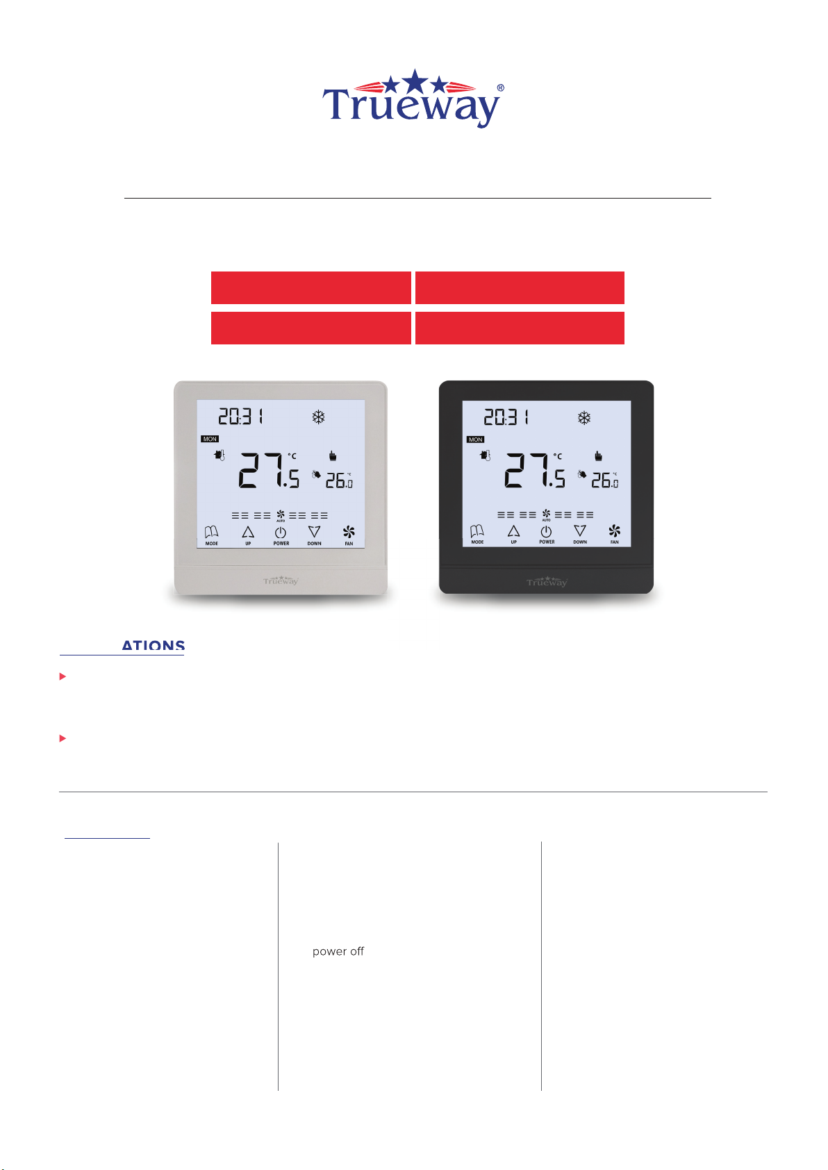
FULLY TOUCH SCREEN SERIES
MODEL
TX986ML220-V2KTX986ML220-V2E
FULLY TOUCH SCREEN SERIES
APPLICATIONS
FEATURES
♦Special colors upon request with
RAL number can be provided.
♦Regular colour available in Black,White
and Silver body
♦User setting can be kept during
♦Both Room and Set point Display
♦Manual & Automatic Fan functions
♦
♦
♦Temperature unit C & F
♦Fan load 5A resistive and inductive of
3A (fan load 8A resistive can provide on
request)
♦13 terminal power box fits in 86cm x 86 cm
& 9 terminal power box fits in 75cm x 75cm
electrical junction box
1
A
TION
S
TX986ML024-V2KTX986ML024-V2E
TX986 series is fully touch screen thermostat with many variants suitable for 2 pipe/4 pipe cooling & Heating Fan coil units and
DX single stagecompressor units. We introduce Bacnet and Modbus communication in this series. Option of 9 terminals & 13
terminals power box can occupy addons Like AO,AI,DO and DI as per convenience
Available in dierent colour body option with sky blue and black backlight. Fitted with built-in NTC10K sensor and optional Humidity
sensor. Several external functions like remote sensor,key card, PIR sensor, Light controls are available in dierent variants as per
site requirement
♦
♦
♦
♦
♦
♦ Black LCD and Sky-blue LCD
display selectable
Modern Fully touchscreen
design,suitable for oces, Hotels
and residential buildings.
Modbus RS485
Communicating.
Applicable for 2 pipe/4 pipe
fan coil unit cooling & heating.
Applicable for Dx single stage
compressor Units.
Big LCD with English only display
EC motor variants available.
User setting can kept during power o
Real Time clock with infinite life
battery backup
♦
W
FULLY TOUCH SCREEN SERIES
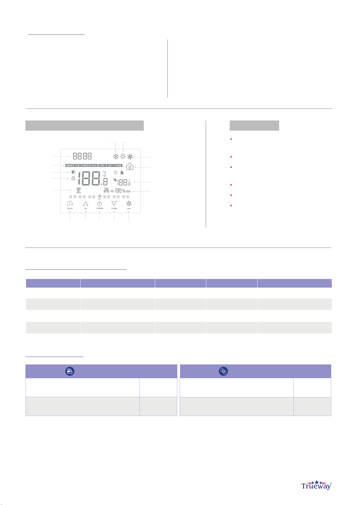
LCD DISPLAY & KEYS DESCRIPTION FUNCTION
2-pipe FCU cooling&heating,
Modulating 0-10V output
3 Speed Fan + Auto Fan Control
Energy Save Mode and
Comfort Mode Settings
7 Days 6 Periods Programmable Function
Key Pad Lock
Both Room and Set-Temp Display
SPECIFICATION
♦Power supply 12v/24v/85-220v based on variants
Frequency:50~60Hz
♦Function: Cooling/Heating
♦Relay Life: 220±10% VAC, 3(5)A, 100,000 times
♦Wiring Max: 16AWG
♦Sensing Element: 10K(@25°C) NTC
♦Display Accuracy: 1°C, Set-point accuracy: 1°C/step
♦Set-point range: 10-32°C(50-90°F) • Display range: 0-50°C
♦Protection Glass: IP 20 • Operation Temperature: -18~49°C
♦Shipping Temperature: -35~65°C Suitable System: 2-pipe
/ 4-pipe FCU
♦Suitable Valve: 2-line/3-line valve • Relative Humidity: 10~90%
♦13 terminal power box fits in 86cm x 86 cm & 9 terminal power
box fits in 75cm x 75cm electrical junction box
ORDERING PART NUMBERS
TX986ML220-V2E 85-240VAC 2-PIPE 0-10VDC EXTERNAL SENSOR
TX986ML220-V2K 85-240VAC 2-PIPE 0-10VDC HOTEL KEYCARD
TX986ML024-V2E 24VAC 2-PIPE 0-10VDC EXTERNAL SENSOR
TX986ML024-V2K 24VAC 2-PIPE 0-10VDC HOTEL KEYCARD
PART NUMBERS OPERATING VOLTAGES APPLICATIONS VALVE TYPE ADDON FUNCTIONS
ABBREVIATION
CASING/COVER COLOR BACKLIGHT COLOR
WHITE
BLACK B
*ordering example TX986ML024-V2K-WSB
BW
Sky Blue backlight + Black letters(TN LCD)
Black backlight + White letters (VA LCD)
SB
2
Ventilation Mode
Periods Display
Set Temp.
Valve Open or Close,
Humidity / Modbus ID
Checking
FanDownUp PowerMode
Energy Saving
Mode
Key Lock
Room Temp.
Weekdays
Clock Display
Cooling Mode Heating Mode
By pressing MODE for 3 seconds can activate the energy saving mode with icon appearing on the screen. If energy saving is
activated by button pressed, pressing any button will stop energy saving mode. For heating mode, if energy saving function is enabled, the
set-point will be changed to remote setback heating set-point. The range of remote setback heating set-point is from 10 °C to 21 °C and
default value is 18 °C. The value can be changed in ISU mode with step of 1 °C. For cooling mode, if energy saving function is enabled, the
set-point will be changed to remote setback cooling set-point. The range of remote setback cooling set-point is from 22°C to 32°C and
default value is 26 °C. The value can be changed in ISU mode with step of 1 °C .
FULLY TOUCH SCREEN SERIES
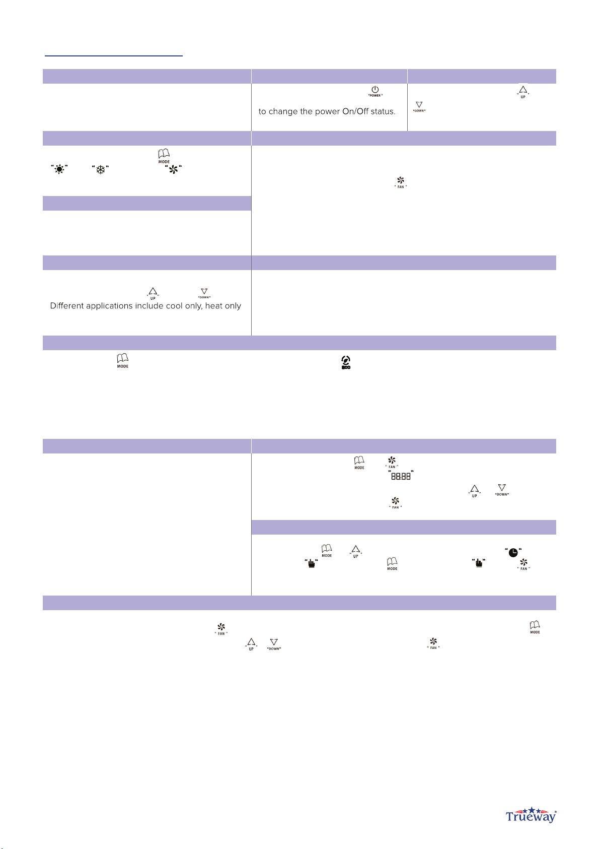
OPERATION INSTRUCTION
MODULATING VALVE CONTROL
Thermostat acquires the room temperature via its
integrated sensor and maintains the set-point by
modulating output.
POWER ON OR OFF
By pressing POWER button
INCREASE / DECREASE
In the ON state, press UP or
DOWN to increase or decrease
the setting parameters.
FAN OPERATION
HEAT/COOL/VENT
Pressing the MODE button to select heat
cool or ventilation mode.
TEMPERATURE DISPLAY
Both the room temperature and the set-point
are displayed.
COMFORT MODE
In the comfort mode, the set point can be
changed by pressing UP or DOWN buttons.
and manual heat/cool changeover.
KEY LOCK
The default status of “Key lock” is all keys available and it can be changed in
ISU mode. Key lock function includes the following settings: All keys are
available (Default) System button is locked out. Fan and system buttons are
locked out . All buttons are locked . The following operating modes are available :
ENERGY SAVING MODE
FREEZE PROTECTION MODE
Freeze protection can be disable(default) or
enabled via ISU mode. If freeze protection is
enabled( it is not available in cooling only
application) and thermostat is in OFF mode while
the room temperature is below 6 °C , the
thermostat will open heating device before the
temperature rises to 8 °C
TIME SETTING
In ON/OFF states, press and for 5 seconds, you will hear Bee sound
“bibi” for twice, and the time area will be flashing,
press to select minutes, hours or week, then press or
to adjust the relevant time, press to confirm.
TO SELECT MANUAL AND PROGRAMMABLE
ADJUSTING OF WEEKLY PROGRAMMABLE
3
Press and hold and for more than 5 seconds, the icon of or will
flash, press to select manual or programmable press to
confirm.
After selected programmable mode, press for more than 5 seconds, you will hear Bee sound “ bibi” twice, then press to
select setting item of periods, time and temp. press or to adjust the relevant value, press to confirm. The sequence: 5+2
programmable mode, time adjusting temperature adjusting from 1-6 periods of Monday to Friday time adjusting temperature
adjusting from 1-2 periods of Saturday and Sunday (5+2programable mode, 5 every mode has 6 periods and 2 every mode has 2
periods)
Pressing the MODE button to select heat
, press UP or
D
Fan can be selected as manual or automatic 3-speed operation. In manual
mode, the fan will be switched to the selected speed via controls output
Gh,Gm,Gl (by pressing FAN button ). In automatic mode, the fan speed
will be switched upon dierence between the room temperature and set
point. When room temperature reaches set-point, valve will be closed
meanwhile, fan will be turned o as well (fan can be changed to low
speed via ISU setting code 17).
Gh,Gm,Gl (by pressing FAN button ). In automatic mode, the fan speed
, the set point can be
changed by pressing UP or D
WN buttons.
By pressing MODE for 3 seconds can activate the energy saving mode with icon appearing on the screen. If energy saving is
In ON/OFF states, press and for 5 seconds, you will hear Bee sound
flash, press to select manual or programmable press to
Press and hold and for more than 5 seconds, the icon of or will
After selected programmable mode, press for more than 5 seconds, you will hear Bee sound “ bibi” twice, then press to
In ON/OFF states, press and for 5 seconds, you will hear Bee sound
flash, press to select manual or programmable press to
After selected programmable mode, press for more than 5 seconds, you will hear Bee sound “ bibi” twice, then press to
select setting item of periods, time and temp. press or to adjust the relevant value, press to confirm. The sequence: 5+2
, press to confirm.
press to select minutes, hours or week, then press or
Press and hold and for more than 5 seconds, the icon of or will
press to select minutes, hours or week, then press or
select setting item of periods, time and temp. press or to adjust the relevant value, press to confirm. The sequence: 5+2
select setting item of periods, time and temp. press or to adjust the relevant value, press to confirm. The sequence: 5+2

ADJUSTING OF WEEKLY
PROGRAMMABLE
MON TUE WED THU FRI SAT SUN
IN PROGRAMMABLE MODE, SET-POINT
AND TIME COULD NOT BE ADJUSTED
06:00AM
08:00AM
11:30AM
12:30PM
17:00PM
22:00PM
06:00AM
23:00PM
1
2
3
4
5
6
1
2
PERIODS
WORKDAYS
WEEKEND
SYMBOLS DEFAULT TIME DEFAULT TEMP.
22 C
22 C
22 C
22 C
22 C
22 C
22 C
22 C
PERIODS
DESCRIPTION
1ST PERIOD, WAKE UP
2ND PERIOD, LEAVE
3RD PERIOD,
BACK FROM LUNCH
4TH PERIOD, LEAVE
5TH PERIOD,
BACK FROM DINNER
6TH PERIOD, WAKE UP
SYMBOLS
DESCRIPTION
NO FUNCTION SETTING AND OPTIONS
1 SYSTEM TYPE
2 TEMPERATURE UNIT SETTING 0 > ° F
1 > ° C
3 FAN CONTROL TYPE
0 > AUTO ONLY
1 > CONSTANT ONLY
2 > BOTH(DEFAULT)
4
5
6 FREEZE PROTECTION
7 DISPLAY TEMP. ADJUSTMENT
8 REMOTE SETBACK HEATING MODE RANGE 10-21°C ( RANGE 50-70°F )
9 REMOTE SETBACK COOLING MODE RANGE 22-32°C (RANGE 72-90°F
4
SETUP FUNCTION SETTINGS AND OPTIONS
a. Press and key for 5 seconds to enter ISU setting mode, the ISU code will be flashing.
b
c.
. Press or to select the setting items from 1-26. press to confirm.
Press and revise the values of the setting items, press to confirm.
If you want to revise the other setting items, please repeat above step b. and c. while setting, press to exit, the setting items
and values as below form shown.
FULLY TOUCH SCREEN SERIES
Press and
. and c. while setting, press to exit, the setting items
Press and
. Press or to select the setting items from 1-26. press to confirm.
Press and revise the values of the setting items, press to confirm.
. Press or to select the setting items from 1-26. press to confirm.
Press and revise the values of the setting items, press to confirm.
. Press or to select the setting items from 1-26. press to confirm.
Press and revise the values of the setting items, press to confirm.
0 > Heat only
1 > Cool only
2 > Two pipes 1H1C manual(Default)
KEY LOCK SETTING
N/A
0 > ALL KEYS ARE AVAILABLE (DEFAULT IS 0 )
1 > SYSYEM BUTTON IS LOCKED OUT
2 >
3 > ALL BUTTONS ARE LOCK OUT
ONLY RESERVED FOR OTHER MODEL SETTING
THIS ITEM IS NOT AVAILABLE(RESERVED FOR
OTHER MODEL’S ISU MODE SETTING)
0 > DISABLED ; 1 > ENABLED
-2 °C(-4°F); -1.5°C(-3°F) -1°C(-2°F) -0.5°C(-1°F)
0°C(0°F), 0.5°C(1°F) 1°C(2°F) 1.5°C(3°F) 2°C( 4°F )
DEFAULT
2
1
2
0
0
0.0 °C (0°F) )
18°C( 64°F)
26°C( 79°F)

FULLY TOUCH SCREEN SERIES
12 I : ADJUSTMENT OF VALVE CONTROL
13 SENSOR SELECTION
14 BEE SOUND SETTING 0 > ON ; 1 > OFF
15 PROGRAM SETTING
17 FAN STOP/RUN SETTINGS
16 0-4 MINUTES, WHEN THE SETTING IS 1, WITH 1 MINUTE
DELAY FOR BOTH ON OR OFF THE COMPRESSOR.
18 ON / OFF BACK-LIGHT SETTING
WHEN STANDBY
19 ON / OFF MEMORY SETTING
21 VALVE OPEN VALUE SETTING
22
24
25
26
20 BACK-LIGHT SETTINGS
RESERVED FOR ADDITIONAL ISU SETTINGS
23 RESERVED FOR ADDITIONAL ISU SETTINGS
RESERVED FOR ADDITIONAL ISU SETTINGS
RESERVED FOR ADDITIONAL ISU SETTINGS
RESERVED FOR ADDITIONAL ISU SETTINGS
10 MODBUS ID DISPLAY SETTING
11 P : ADJUSTMENT OF VALVE CONTROL
5
MINI. OUTPUT ON/OFF TIME
0 > OFF(NO DISPLAY OF MODBUS ID) ; 1 > ON(DISPLAY)
RANGE:1-10 FOR PROPORTIONAL OUTPUT ADJUSTMENT,
IT SHOULD BE ADJUSTED BASES ON THE ACTUAL
CONDITION
RANGE:1-60 INTEGRAL OUTPUT ADJUSTMENT,
IT SHOULD BE ADJUSTED BASES ON THE
ACTUAL CONDITION
0 > INTERNAL SENSOR(BUILT-IN) ; 1 > EXTERNAL
SENSOR
0 > 5 WORKING DAYS A WEEK ;
1 > 6 WORKING DAYS A WEEK ;
2 > 7 WORKING DAYS A WEEK;
3 > CLOSE THE PROGRAM SCHEDULE;
PS: IF YOU SELECTED 7 WORKING DAYS A WEEK, THE
WHOLE SCHEDULE IS SAME(ONLY 6 PERIODS), IF YOU 5
WORKING DAYS A WEEK, IT WILL HAS 2 TYPES OF PERIOD
FOR THE WEEK, WORKING DAYS 6 PERIODS, AND WEEKEND
(HOLIDAYS) IS 2 PERIODS
0 > FAN WILL BE SWITCHED TO LOW SPEED WHEN THE
VALVE TURNS OFF
1 > FAN WILL BE TURNED OFF WHEN THE VALVE TURNS
OFF
0: OFF, THE BACK-LIGHT WILL BE OFF ALWAYS EVEN THE
USER PRESSING ANY KEY
1: ON, THE BACK-LIGHT WILL BE ON FOR ABOUT 15
SECONDS IF ANY KEY PRESS
0: OFF, USER SETTING WILL NOT KEEP WHEN POWER OFF
(WHILE ELECTRIFIED, THE THERMOSTAT WILL BE OFF)
1: ON, USER SETTING WILL BE KEPT WHEN POWER OFF
(WHILE ELECTRIFIED, THE THERMOSTAT WILL BE ON
10-60 SECONDS(USER CAN ADJUST BACK-LIGHT TIME
ACCORDINGLY TO ACTUAL DEMANDS)
0: OFF, THE VALVE OPEN VALUE WILL NOT BE DISPLAYED
ON THE LCD
1: ON, THE VALVE OPEN VALUE WILL BE DISPLAY ON LCD
(ONLY AVAILABLE FOR MODULATING TYPE THERMOSTAT
0
4
25
0
1
0
3
0
0
0
15
0

FULLY TOUCH SCREEN SERIES
9 TERMINAL POWER BOX
*wiring is subject to change without notice based on addons
PRODUCT DIMENSION
6
NOTE:
♦ The thermostat is high voltage input, please do wiring with technician.
♦ If the thermostat was burned by accidently, please do not wiring it again by yourself, try to check it with a professional technician or contact
with our manufacturer.
WIRING DIAGRAM
NO
1LLIVE LINE IN
3FH HIGH SPEED FAN
4FM MEDIUM SPEED FAN
2
DESCRIPTION
5FL LOW SPEED FAN
6NNEUTRAL IN
7
COM COM FOR MODULATING VALVE &
EXTERNAL SENSOR/ KEY CARD
8
AO ANALOG OUTPUT 0-10VDC
9AI / DI EXTERNAL SENSOR/KEY CARD
TERMINALS
NO
1R24 V ACTIVE
3FH HIGH SPEED FAN
LINE 220V LINE FOR FAN
4FM MEDIUM SPEED FAN
2
DESCRIPTION
5FL LOW SPEED FAN
6C24V NEUTRAL
7AO ANALOG OUTPUT 0-10VDC
8COM COM FOR MODULATING VALVE &
EXTERNAL SENSOR /KEY CARD
9AI / DI EXTERNAL SENSOR / KEY CARD
TERMINALS
Fan
TX986ML220-V2E
(0-10VDC)
AI (External Sensor)
COM
(0-10VDC)
Fan
85-240VAC
TX986ML220-V2K
DI(key card)
COM
Fan
24VAC
TX986ML024-V2E
(0-10VDC)
AI (External Sensor)
COM
Fan
24VAC
TX986ML024-V2K
(0-10VDC)
DI(key card)
COM
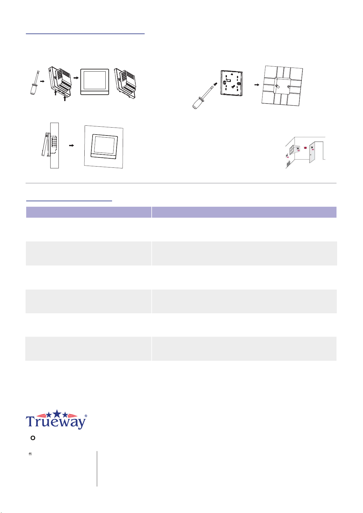
INSTALLATION AND COMMISSIONING
T uch makes you Comfortable
O ce:
Trueway Controls Hong Kong Limited
Room 1318-19 Hollywood Plaza,
610 Nathan Road, Mongkok,
Kowloon, Hong Kong.
Factory:
4F, Building A2,
Nanxi Industrial Area,
Xiangzhou District,
Zhuhai, China.
TROUBLE SHOOTING TIPS
IF... THEN...
The fan doesn’t work
Heating system does not turn on Set the mode to Heat by pressing the Mode button.
Wait five minutes for the heating system to respond.
Cooling system does not turn on Set the mode to Cool by pressing the Mode button.
Wait five minutes for the cooling system to respond.
The Mode button does not work
The Fan button does not work
1. To take the front panel and back plate apart by screwdriver
3. Recombine the front panel and back plate by contract pins.
2. Wiring on the terminals of the back plate according to above
wiring diagram, then fix the back plate on the junction box by
screw driver
Install the thermostat about 5 feet(1.5m) above the floor in an area with
good air circulation at average temperature.
Do not install in locations where the thermostat can be aected by:
1. Drafts or dead spots behind doors and in corners
2. Hot or cold air from ducts
3. Sunlight or radiant heat from appliances
4. Concealed pipes or chimneys
5. Unheated/uncooled areas such as
an outside wall
Check whether the Fan mode is set to Auto.
Check whether the heating or cooling system works well or not.
Check whether the Keypad is locked or not(ISU setting code 4).
Check whether the system is working in Energy saving mode.
Check whether the thermostat is o.
Check whether the Keypad is locked or not(ISU setting code 4).
Check whether the system is working in Energy saving mode.
Check whether the thermostat is o.
The Up or Down button does not work
Check whether the Keypad is locked or not(ISU setting code 4).
Check whether the system is working in Energy saving mode.
Check whether the thermostat is o.
This manual suits for next models
3
Table of contents
Other Trueway Thermostat manuals


Popular Thermostat manuals by other brands

Motison
Motison CyberStat CY1201 user manual

Honeywell
Honeywell RTH6400 Series Quick installation guide

Venstar
Venstar ColorTouch T5800 Owner's manual and installation instructions

Honeywell
Honeywell RTH6500WF Wi-Fi Series user guide

Strom
Strom SSRTPR05 user guide

meitav-tec
meitav-tec SUPER-SI Series User's manual & installation instructions


