Superior Electric STABILINE DIN2R-40 Series User manual

1 Ø, 120 VAC, 2-Wire, w/ground L-N, N-G 1 1
1 Ø, 120/240 VAC, 3-Wire SPLIT-PHASE, w/ground L-N / L-N, N-G 2 1
3 Ø, 208Y/120 VAC, 4-Wire WYE, w/ground L-N / L-N / L-N, N-G 3 1
1 Ø, 220 VAC, 2-Wire, w/ground L-N, N-G 1 1
3 Ø, 380Y/220 VAC, 4-Wire WYE, w/ground L-N / L-N / L-N, N-G 3 1
3 Ø, 220 VAC, 3-Wire DELTA L-L / L-L / L-L 3 N/A
1 Ø, 277 VAC, 2-Wire, w/ground L-N, N-G 1 1
3 Ø, 480Y/277 VAC, 4-Wire WYE, w/ground L-N / L-N / L-N, N-G 3 1
1 Ø, 480 VAC, 2-Wire, w/grounded neutral L-L, N-G 1 1
3 Ø, 380 or 480 VAC, 3-Wire DELTA L-L / L-L / L-L 3 N/A
DIN2R-40-NG1 120, 120/240, 220, 277, 380, 480 VAC Neutral to Ground N-G N/A 1 600 VAC 40 kA 20 kA 800 VAC 500 VAC
DIN2R-40-277-L1
DIN2R-40-480-L1
Nominal Surge
Current Rating
UL 1449
SVR Rating
1800 VAC20 kA550 VAC
40 kA
40 kA
DIN2R-40-120-L1
C3 Comb
Wave
Surge Performance Specifications
Max Surge
Current Rating
800 VAC 1000 VAC
20 kA
20 kA
20 kA
40 kA
40 kA
2100 VAC
500 VAC 500 VAC
700 VAC 900 VACDIN2R-40-220-L1
STABILINE
Model
Typical
System Voltage / Service Configuration Protection Mode
150 VAC
255 VAC
320 VAC
Protector Quantity
Line
Voltage N-G MCOV
SPECIFICATIONS
Electrical Specifications
Modes of Protection: L-N; L-G; L-L protectors use MOV technology
and N-G protector use Gas Tube.
Input Power Frequency: 47-64 Hz
Associated Fusing: DIN2R-40 protectors incorporate an internal thermal
disconnect system with time-delayed Class J,30A-125A over current fuses.
Environmental Specifications
Operating Temperature: -40° C to 85° C (-40° F to 185° F)
Relative Humidity: 5% to 95% non-condensing
Max. Operating Altitude: 4,000 meters (13,000 feet)
Mechanical Specifications
Enclosure: IP20 enclosures (UL94V0 thermoplastic housing material).
Replaceable plug-in surge protection module and fixed base.
Mounting: Din Rail 35mm symmetrical
Connection Method: Screw terminal # 4 - 10 AWG
Size (H x W x D): 3.5 x .71 x 2.63 inches (90.0 x 18.0 x 67 mm)
Weight (Shipping): 0.25 lbs (0.11 kg)
General Specifications
Standards Compliance and Safety Approvals: Meet UL 1449, 2nd Edition,
EN61643-11 (Europe), ANSI/IEEE C62.41-2002, NF EN 61643-11 (France),
VDE0675-6, CSA-22.2 and CE marked.
Warranty: Ten Years
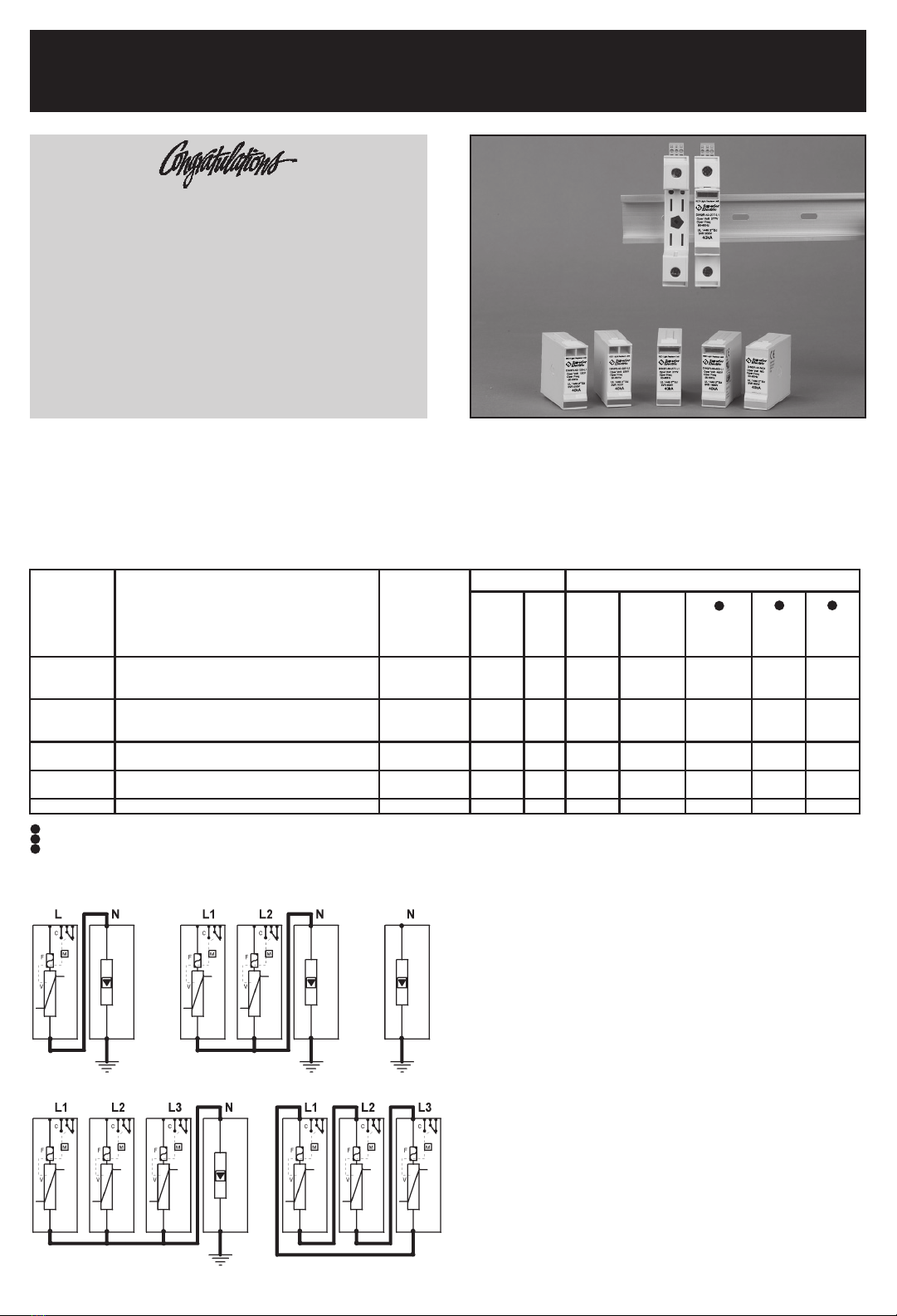
STABILINE® Transient Voltage Surge Suppressors
DIN2R-40 Series - OWNERS MANUAL
MODEL NUMBER & Typical System Voltage / Service Configurations
Thank you for purchasing the DIN2R-40 Series
STABILINE Transient Voltage Surge Suppressor
... another Superior product!!
Expect exceptional performance. The unit is built
to the highest standards for your complete satis-
faction.
To assure many years of uninterrupted service,
please read this Owners Manual to familiarize
yourself with the operation and proper installation
of the DIN2R-40 Series unit.
TYPICAL SERVICE CONFIGURATIONS Contact Factory for addititional configurations
For a minimum of (20) 8 x 20usec surges
UL 1449 2nd Edition, (6kV, 500A 8 x 20usec) Surge Voltage Rating
C3 Combination Wave, 20kV, 8 x 20usec, 10 kA
1
2
3
1 Ø, 2-Wire, w/ground 1 Ø, 120/240 VAC, 3-Wire
SPLIT-PHASE, w/ground
3 Ø, 4-Wire WYE, w/ground 3 Ø, 3-Wire DELTA
Neutral to Ground
132
DIN2R-40 Series STABILINE®Transient Voltage Surge Suppressors are single pole, parallel-connected, MOV
technology Class II, Category B Surge Protective Devices suitable for use in AC electrical power systems for
protection against surge and transient activity. DIN2R-40 Series protectors provide 40 kA Surge Amp Capacity
protection in a maintenance free, low profile, DIN Rail mountable module. DIN2R-40 Series feature a replaceable
plug-in surge protection module and fixed base which allows for easy and fast maintenance.

©2007 Superior Electric
REMOVE POWER FROM ELECTRICAL SYSTEM PRIOR TO
INSTALLATION.
The DIN2R-40 protectors are installed/connected in Parallel with the line
and the equipment to be protected.
The DIN2R-40 Series unit should be installed down stream of a 125 A
maximum fuse or breaker (see diagram). If pre-existing fuses or breakers
are present, then the fusing or breaker used for the DIN2R-40 protector
should have a lower rating in order to be properly coordinated, as per
applicable electrical regulatory standards. The Short Circuit current rating
for these DIN2R-40 protectors are 25,000 Amps using a 50A Class J time
delayed fuse.
The Importance of Correct Installation
THE FOLLOWING IS INTENDED FOR QUALIFIED ELECTRICAL
PERSONNEL ONLY. COMPLETELY READ THESE INSTRUCTIONS
BEFORE INSTALLATION. IT IS THE FINAL RESPONSIBILITY OF THE
INSTALLING ELECTRICIAN TO ENSURE THAT ALL LOCAL CODES
AND OTHER APPLICABLE SAFETY/ENVIRONMENTAL CONDITIONS
ARE MET AND THE UNIT IS CORRECTLY INSTALLED.
This manual provides guidelines for the proper installation of DIN2R-40
Series units. Proper product selection and compliance with these guidelines
will help your new suppression system provide years of reliable service.
If installer’s are unsure about the facility’s electrical configuration or have
other installation-related questions, we recommend they consult with a
master electrician or other qualified electrical professional.
WARNING! The DIN2R-40 Series Warranty is voided if
the unit is damaged as a result of improper installation
or the installer’s failure to verify the voltage and
power configuration of the DIN2R-40 unit with the
installation voltage and service configuration at the site.
Improper installation or misapplication of these devices
may result in serious injury to the installer and/or damage to
electrical system(s) or related equipment. Protective eyewear
should be worn during the installation process.
Installation
The DIN2R-40 protector is a maintenance free device. If the unit is
subjected to a prolonged over-voltage condition, an internal thermal
element will activate, disconnecting the DIN2R-40 from the line. When
the unit is no longer providing protection the window on the front of the
DIN2R-40 becomes red and a replacement unit will be required.
Remote Signal
DIN2R-40 protectors (except N-G protector) come standard with one remote
monitoring relay with “dry Form C contacts” per module. The contact can
be used to drive several different types of indicators such as a remote light
indicator or an audible alarm. The signal strength is (Vmax:250V rms, Imax:
2A). The connection to the remote signal is through the screw terminals.
Maintenance
SAVE THESE INSTRUCTIONS!!
28 SPRING LANE • SUITE 3
FARMINGTON, CT 06032 USA
www.superiorelectric.com
213709-234 REV A Printed in USA
Toll-Free (in USA and Canada only)
Telephone
Fax
Customer Service
Product Application
1-800-787-3532
1-800-821-1369
1-800-787-3532, Ext. 70782
1-800-787-3532, Ext. 72058
Telephone and Fax Numbers
Telephone
Fax
Customer Service
Product Application
860-507-2025
860--507-2050
860-507-2025, Ext. 70782
860-507-2025, Ext. 72058
N
L2
L1
L3
To w a r d
Ground
Network
Installation
Delayed RDC Breaker
Ground
Disconnection
Indicator
Total length of the wires
0-2 ft. (0-0.5m)
<
Fuses
(125 A type gG)
Breaker
(125 A)
Service Configuration
3Ø, 4 wire WYE, w/ground
2.63 in (67mm)
3.5in (90mm)
2 in (51mm)
.42 in (11mm)
.71 in (18mm)
Inches (mm)
L/N
F
C
11
12
14
V
V : Heavy Duty Varistor
F : Thermal Fuse
C : Remote and Signal Contact
t : Thermal Disconnect
M: Monitor (Window)
M
Dimensions
DO NOT INSTALL THE DIN PROTECTOR IF MEASURED VOLTAGE
EXCEEDS UNIT RATINGS.
The DIN2R-40 protector MUST BE mounted in an enclosure to assure
personnel safety from exposed terminals. Mechanically mount the
DIN2R-40 protector utilizing customer supplied Din-Rail.
Wiring connection between the DIN2R-40 protector and protected equipment
should be kept as short as possible. Superior Electric recommends that
wire lengths be less than 20 inches (0.5m). Wire should be straight and
should not contain 90 degree bends. If bends are required, they should
be sweeping bends.
Unprotected cables should not be installed in parallel with the protected
cables. This will minimize coupling of inductively induced surges onto
unprotected cables.
Internal Protector Schematics
N
Gas
Tube
Line Voltage Protector Neutral to Ground Protector
* These INSTRUCTIONS are subject to change without notice.
This manual suits for next models
5
Other Superior Electric Surge Protector manuals

Superior Electric
Superior Electric STABILINE CS1 Series User manual

Superior Electric
Superior Electric STABILINE DIN3-70 Series User manual

Superior Electric
Superior Electric STABILINE DIN3-165 Series User manual

Superior Electric
Superior Electric Stabiline TB1 Series User manual

Superior Electric
Superior Electric STABILINE PT2 Series User manual