superior fires SF12-212-000 Guide
All instructions must be handed to the user for
safekeeping.
Please note : Except where otherwise stated, all rights, including copyright in the
text, images and layout of this booklet is owned by Focal Point Fires plc. You are not
permitted to copy or adapt any of the content without the prior written permission
of Focal Point Fires plc.
1
Revision A - 07/15
© 2015 Focal Point Fires plc.
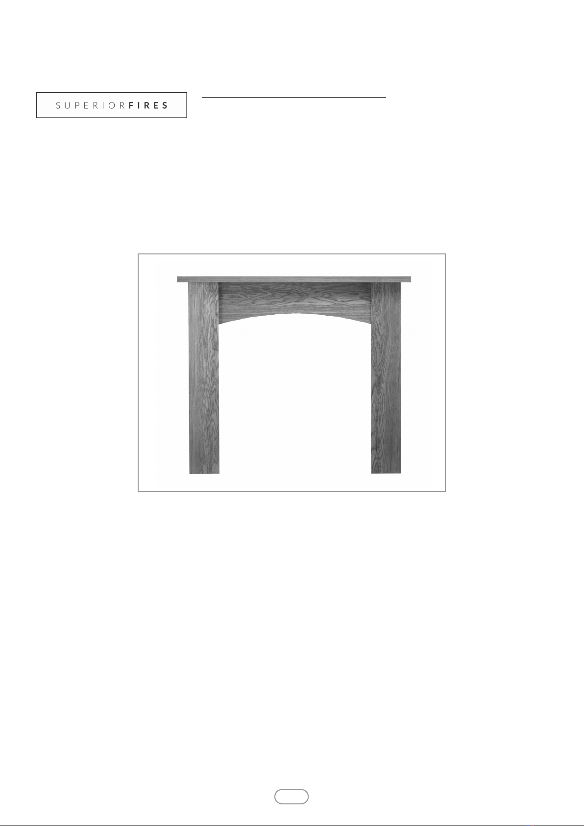
MODEL SHOWN: WELLINGTON OAK
INSTALLATION & ASSEMBLY INSTRUCTIONS
WOODEN FIRE LACE SURROUND
MODELS COVERED BY THESE INSTRUCTIONS
WELLINGTON OAK FIRE LACE SURROUND - SF12-212-000
WELLINGTON WHITE FIRE LACE SURROUND - SF12-211-000
WELLINGTON WALNUT FIRE LACE SURROUND - SF12-213-000
NEBRASKA OAK FIRE LACE SURROUND
NEBRASKA WHITE FIRE LACE SURROUND
NEBRASKA WALNUT FIRE LACE SURROUND
Superior Fires
Christchurch, Dorset BH23 2BT
Tel: 01202 588 632
Fax: 01202 499326
www.superiorfires.co.uk
Email : [email protected].uk

A S S E M B L Y I N S T R U C T I O N S GB IE
1.0 IM ORTANT NOTES
Section
1.0
2.0
3.0
4.0
Contents
Important notes
Tools required
Hardware & parts list
Assembly
age No.
2
2
2
3
Section
5.0
6.0
7.0
Contents
Installation
Cleaning/ finishing
Guarantee - terms and conditions
age No.
5
5
5
2.0 TOOLS REQUIRED
CODE NA E FIGURE QUANTITY
A
WOOD
DOWELS
(8X20mm)
19PCS
B CA LOCKS
(15X9mm)
12PCS
C CA BOLTS
(6X30mm)
12PCS
D
WOOD
SCREWS
(8X25mm)
13PCS
E
WALL
SCREWS
(8X38mm) 2PCS
F
WOOD
SCREWS
(3X20mm)
4PCS
G WALL PLUGS
(6X25mm)
2PCS
3.0 HARDWARE & ARTS LIST
CODE NA E FIGURE QUANTITY
①TOP PANEL 1PC
②FRONT PANEL 1PC
③LEFT SIDE
LEG
1PC
④RIGHT SIDE
LEG
1PC
⑤INSIDE LEGS 3PC
⑥LEFT SIDE
PANEL
1PC
⑦RIGHT SIDE
PANEL
1PC
To ensure safe and stable installation:
1. The assembled Fire Surround must be fixed / secured to wall.
2. The wall must be sturdy and in good repair.
3. Some walls require alternative fixings (not included).
4. When drilling into the wall, check for hidden pipes and cables.
Cross head screwdriver PZ2 (3 inches in length or greater)
Drill, 6mm and a 2mm suitable drill bit
Pencil
Tape measure
H
IRROR
PLATES
(45X43mm)
2PCS
IGLUE
(10g)
1PCS
2© 2015 Focal Point Fires plc.

4.0 ASSEMBLY
3
GB IE
© 2015 Focal Point Fires plc.
Fixings Parts
A x 4 PCS 2
D x 4 PCS 3
4
A
A
DD
D③
Gently lay both legs you have prepared onto a suitable protected surface. Be extremely careful not to scratch the front edges
of the legs. DO NOT DRAG THE LEGS! ake sure that the legs are lifted everytime they are moved to avoid them from being
damaged.
Using a drop of glue (I) in each dowel hole, insert two dowels (A) in to the left leg (3). Again, using a drop of glue (I) in the
dowel holes take the front panel (2) and push them on to the dowels (A). Use 2x wood screws (D) to screw the parts togeth-
er. Repeat the process for the right leg using the right leg (4) and front panel (2).
④
STEP 1
STEP 2
Using a drop of glue (I) in each dowel hole, insert 2x dowels (A) in to the left leg (3). Again, using a drop of glue (I) in the
dowel holes take the inside leg (5) and push them on to the dowels of the leg (3). Use 3x wood screws (D) to screw the right
side panel (5) to the right leg (4). Repeat the process to secure the third inside panel (5) to the front panel (2).
Fixings Parts
A x 6 PCS 2
D x 9 PCS 3
4
5
④
A
D
②
D
A
A
A
D
③
②
A
A
A
AA
A
D
D
D
D
D
D
D
D
D
⑤
⑤
⑤

4.0 ASSEMBLY - CONTINUED GB IE
4© 2015 Focal Point Fires plc.
STE 3
Use the Glue (I) in the dowel holes before inserting 2x dowels (A) into the left and right hand legs (3 and 4). Position the cam
bolts (B) in to left and right side panels (3 and 4).
Take the left side and the right side panels (6 and 7), put some glue (I) in to the dowel holes. Insert the cam locks (B). Screw
the cam bolts (C) in to the left and right legs (3 and 4). Position the left and right sides (6 and 7) onto the dowel joints (A) and
cam bolts (C) in the legs (3 and 4). Now turn the cam locks (B) clockwise to lock the parts together.
Fixings
A x 4 PCS
B x 6 PCS
C x 6 PCS
Insert 6x cam locks (B) and glue (I) 5x dowels (A) into the legs and front panel (2,3&4). Next prepare the top panel (1) by
screwing all 6x cam bolts (C) into position. The dowel joints (A) need to be glued in at both ends of the top panel. Connect
the top panel to the surround, making sure all 11x inserts are in the correct position. Once home, all 6x cam locks (B) can be
tightened into position.
Fixings Parts
A x 5 PCS 1
B x 6 PCS 2
C x 6 PCS 3
4
②
A
A
A
A
④
③
STE 4
①
④
③
②
B
C
B
B
B
C
C
C
C
C
⑥
⑦
BB
BBB
B
CC
CCC
CC
A
A
A
A
Parts
2
3
4
6
7
A
B
B
⑤
⑤
⑤
B
A
A
B
C

5.0 INSTALLATION GB IE
5© 2015 Focal Point Fires plc.
Fixings
E x 2 PCS
F x 4 PCS
G x 2 PCS
H x 2PCS
With a pencil mark out the desired height where you would like the mirror brackets (H) to be situated on the rear of the legs. To avoid
splitting the leg, pre drill the bracket holes with a 2mm drill bit. Now attach the brackets to the legs using the 3x20mm screws (F). Once
the brackets are in position, centre and level the hearth into its final fitting position. Position the surround on the hearth to correspond
with the header/fireplace lintel, mark with a pencil on the wall where you wish to drill. Remove the surround and prepare the wall from
the marked positions. If using the fixings supplied, drill a hole in the wall using a 6mm drill bit. If not, use a suitable drill bit for the wall
plugs you are using. Insert the wall plugs (G) into position. Offering the surround back up into position against the wall, you are now able
to secure the surround to the wall using the 8x38mm screws (E).
6.0 CLEANING/ FINISHING
Before carrying out any of the following operations, ensure that the appliance is OFF and completely cold. Regularly clean
around the appliance to ensure that dust, fluff, pet hair etc, are kept to a minimum. There are no other specific requirements for
care, other than regular cleaning of the general appliance.
A wipe with a dry cloth is normally sufficient. DO NOT use abrasive cleaners as they can damage the finish. Test on a hidden
part before cleaning. Clean only in the direction of the grain. Regularly check the surround is securely fixed in position.
7.0 GUARANTEE - TERMS AND CONDITIONS
The 3 year guarantee commences from the date of purchase, provided that the terms and conditions are adhered to:
Registration is not required.
1. For any claim to be made within the 3 years from date of purchase you will be required to provide and supply us with your
proof of purchase.
Making a claim is easy.
If you wish to make a claim under our 3 year guarantee and all the terms and conditions for your product have been met then
please submit the following information for the attention of the 3G Service Department to the address below. Alternatively, you
can email or fax. Please note that this does not affect your statutory rights.
Focal Point Fires plc, 3G Service Department, Reid Street, Christchurch, Dorset, BH23 2BT.
Alternatively email: [email protected].uk or fax. 01202 499326.
Details required:
1. Name, full address including post code and contact telephone number.
2. Receipt of purchase or credit card statement.
F861303
F
F
H
E
GG
F
F
H
E
This manual suits for next models
2
Table of contents
Popular Fireplace Accessories manuals by other brands


Town & Country Fireplaces
Town & Country Fireplaces 22150051 instructions

Travis Industries
Travis Industries 33 DVI installation instructions

Lopi
Lopi Hearthview 864 user manual

Lennox Hearth Products
Lennox Hearth Products LENNOX MPE-33R installation instructions

Dimplex
Dimplex DFP6776C install guide

Napoleon
Napoleon W175-0689 instruction manual

Travis Industries
Travis Industries 95400424 installation instructions

Osburn
Osburn ZERO CLEARANCE KIT installation instructions

Majestic
Majestic QUARTZPLA36IN installation instructions

Napoleon
Napoleon DBPO36 installation instructions

Dimplex
Dimplex SMP-130-E install guide

Empire Comfort Systems
Empire Comfort Systems LS50TINF installation instructions