Superior WATERGUARD WG-602 User manual

1
WATERGUARD WG-602
FREE CHLORINE ANALYZER
User Manual
V5.15US January 2018

2
Table of Contents
1General Safety Precautions............................................................................... 4
2Preface.............................................................................................................. 5
2.1 Intended Use............................................................................................... 5
2.2 Safety Precautions...................................................................................... 5
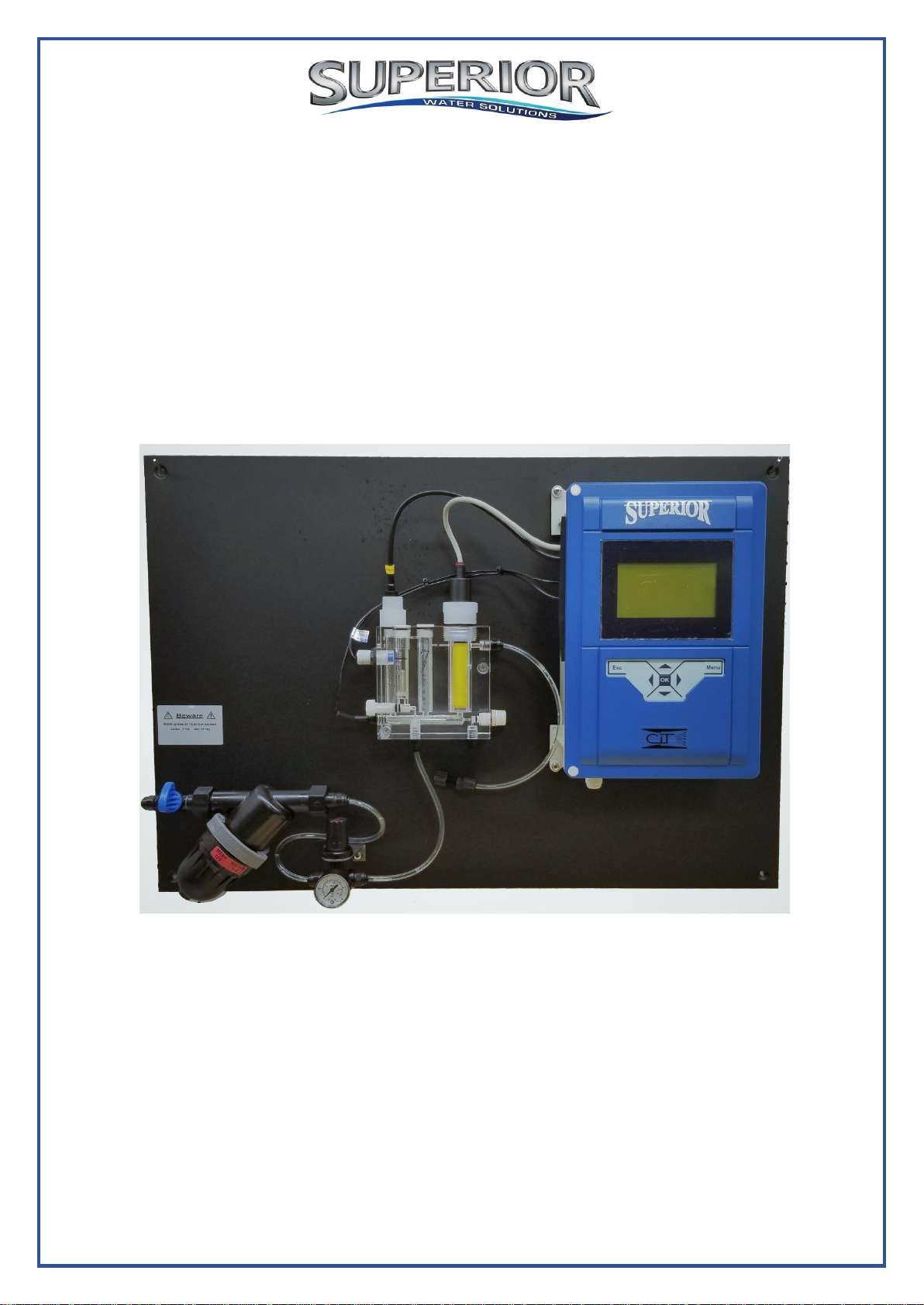
3Overview ........................................................................................................... 6
3.1 Features...................................................................................................... 6
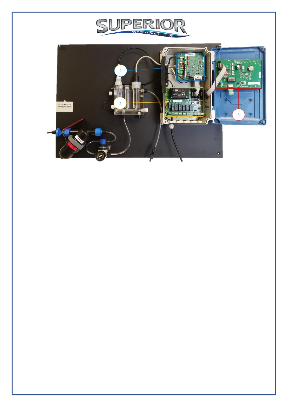
3.2 System Components................................................................................... 6
4Installation....................................................................................................... 13
4.1 Location Considerations............................................................................ 13
4.2 Site Requirements and Installation............................................................ 13
4.2.1 Mechanical Installation....................................................................... 13
4.3 Plumbing Requirements and Installation................................................... 14
4.3.1 Water supply and drain ...................................................................... 14
4.4 Electrical Requirements and Installation.................................................... 15
4.4.1 Connecting the Main Electrical Power................................................ 16
4.4.2 Input Switches.................................................................................... 16
4.5 Installing electrodes .................................................................................. 17
4.5.1 Free Chlorine electrode OCS140....................................................... 17
4.5.2 pH electrode....................................................................................... 19
4.5.3 Temperature sensor........................................................................... 19
5First Time Operation and Calibration............................................................... 20
5.1 Menu Setup............................................................................................... 20
5.2 Operator Menu.......................................................................................... 21
5.3 Technician Menu....................................................................................... 24
5.4 Calibration.................................................... Error! Bookmark not defined.
5.4.1 Temperature Calibration..................................................................... 27
5.4.2 pH Calibration.................................................................................... 28
5.4.3 Chlorine Electrode Calibration............................................................ 29
5.5 4 to 20 mA Output configuration................................................................ 30
6Routine Operation and Maintenance ............................................................... 31
6.1 Filter Cleaning........................................................................................... 31
6.2 Shut-down and Winterizing ....................................................................... 31
6.3 Start-up and Preventive Maintenance ....................................................... 31
6.4 Chlorine Electrode Maintenance ............................................................... 31
6.4.1 Cleaning the electrode....................................................................... 31
6.4.2 Electrolyte Change............................................................................. 32
6.4.3 Membrane Cap Change..................................................................... 32
6.4.4 Storage.............................................................................................. 33
7Technical Specification.................................................................................... 33

3
Table of figures
Figure 1: WG602 FCL Analyzer –General overview……………………………………
7
Figure 2: Acrylic Flow cell Overview………………………………………………….
8
Figure 2a: Acrylic Flow cell Overview…………………………………………………
8
Figure 3: Controller Overview………………………………………………………….
9
Figure 4: Electrodes Card………………………………………………………………
10
Figure 5: I/O Card……………………………………………………………………….
11
Figure 6: Control Panel Card…………………………………………………………..
12
Figure 7: Mounting Panel holes and mechanical installation………………………
14
Figure 8: Water connections, Pressure regulating and flow regulating…………..
15
Figure 9: Free Chlorine electrode…………………………………………………….
18
Figure 10: WG602 FCL Control panel and Display………………………………….
20

4
1 General Safety Precautions
This section presents important information intended to ensure safe
and effective use of this product.
Read the following carefully before handling the product. These
warnings and cautions must be followed carefully to avoid injury to
yourself or damage to equipment.
Warning: Only properly trained and licensed electricians should attempt to wire or service
the electronic components of the analyzer/controller.
There is an Electrical Shock Hazard when servicing this system.
Always verify that all electrical power source(s) are off before opening the
analyzer/controller unit or attempting to service electronic components or wiring.
Caution: Extreme caution should be used when installing, operating, and maintaining the
WATERGUARD®Analyzer. Only properly trained technicians are authorized to install and
maintain the analyzer/controller.
Always follow local health and safety regulations when performing any service on the
analyzer/controller unit or when changing chemical dosing settings.
Each relay connection is limited to 8 amps, to prevent overheating. The relays may show a
higher rating but do not connect equipment exceeding 8 amps.
All electrical connections should comply with National Electrical Code (NEC) and all local
regulations.
Caution: Do not use chemicals that reduce the surface tension. When using hydrochloric
acid, observe all safety regulations.
Electrodes:
Warning: Do not swallow the electrolyte. Avoid electrolyte contact with skin or eyes. In
case of accidental contact, wash with cold water! In case of eye inflammation, contact a
doctor immediately. Wear safety glasses and gloves when working with the electrolyte
solution.
Caution: Do not touch or damage the electrodes. The electrolyte is sensitive to oxidation:
Always keep the electrolyte bottle closed after use. Do not transfer the electrolyte to other
containers. The electrolyte should not be stored for more than one year and should be
clear (not yellow) in appearance (for use by date, see label). Avoid forming air bubbles
when pouring the electrolyte into the measuring chamber.
Caution: WATERGUARD's controller unit should not be opened except for initial
installation and troubleshooting, and should only be opened by a trained and approved
technician.

5
2 Preface
The WaterGuard WG-602 Free chlorine (FCL) is an amperometric chlorine analyzer
that measures free chlorine in water applications.
2.1 Intended Use
This manual is for qualified and trained service technicians who will install and
service the WaterGuard WG-602 Chlorine Analyzer. It provides instructions on how
to install the WaterGuard system, as well as how to calibrate, operate, and maintain
the system.
2.2 Safety Precautions
WARNING
Only properly trained and licensed electricians should attempt to wire or service
the electronic components of the analyzer. There is an Electrical Shock Hazard
when servicing this system. Always verify that all electrical power source(s) are
off before opening the analyzer unit or attempting to service electronic
components or wiring.
CAUTION
Extreme caution should be used wheninstalling, operating, and maintaining the
WaterGuard WG-602 Water Quality Analyzer and Controller. Only properly
trained technicians are authorized to install and maintain the analyzer. Only
properly trained and licensed electricians should attempt any change to the
system’s electrical components. Only properly trained and licensed operators
should attempt to make any changes to chemical dosing levels.
NOTE
Always follow local health and safety regulations when performing any service
on the WaterGuard unit or changing chemical dosing settings.

6
3 Overview
3.1 Features
The WaterGuard WG602 Free chlorine (FCL) is an amperometric chlorine analyzer
that measures free chlorine in water applications. The analyzer includes a free
chlorine electrode, pH and temperature sensors.
The WG602 FCL analyzer includes 2 built-in 4/20 mA analog outputs, and can
support additional 4 analog outputs (total of 6 analog outputs) when required.
The WG602 FCL analyzer includes RS485 digital output that support MODBUS
communication protocol OR BLUE I communication protocol for remote
communication options. For more information about remote communication and
WATERGUARD ON-LINE remote management tools please contact your local
distributor or representative.
The WG602 FCL analyzer supports connection of external conductivity and turbidity
sensors, fully displayed. For more information about conductivity and turbidity
measurements options please contact your local distributor or representative.
3.2 System Components
The WG602 FCL analyzer is a board mounted analyzer and includes all required
components for installation.
The system includes the following components:
1. Controller –includes the display and keyboard panel. Includes 3 electronic
cards: Control panel card, I/O card and electrodes card.
2. Acrylic flow cell –includes free chlorine electrode, pH electrode, Temperature
sensor, flow switch (proximity flow switch), water inlet and outlet ports, and
sampling port.
3. Pre-filter (washable disc filter) –the filter is a 120 micron disc filter and it's
goal is to remove large particles from getting in to the acrylic flow cell.
4. Pressure regulator –the pressure regulator maintains a constant pressure
and flow in the acrylic flow cell, to allow stable readings of the chlorine
electrode.

7
Figure 1: WG602 FCL Analyzer - General overview
1. Controller
2. Free chlorine electrode
3. pH electrode
4. Acrylic flow cell
5. Water inlet (on/off ball valve)
6. Pre-filter (washable disc filter)
7. Pressure regulator
8. Water drain
9. Power connection

8
Figure 2: Acrylic flow cell overview
Figure 2a: Acrylic flow cell overview
1. Free chlorine electrode
2. pH electrode
3. Float (proximity flow switch)
4. Proximity flow switch
5. Flow regulator
6. Temperature sensor
7. Flow cell water inlet
8. Sampling valve
9. Sampling connection
10. Flow cell water drain

9
Figure 3: Controller overview
1. Electrodes card
2. I/O card
3. Control panel card

10
Figure 4: Electrodes card
1. pH electrode [+]
2. pH electrode [-] sheath
3. ORP jumper
4. ORP jumper
5. FCL electrode wire A
6. FCL electrode wire K
7. FCL electrode wire GROUND
8. Temp sensor (color coded)
9. Temp sensor (color coded)
10. Temp sensor (color coded)
11. Temp sensor (color coded)
12. Flat cable from I/O card

11
Figure 5: I/O card
1. Power supply 100-230 VAC
2. Control output Cl1
3. Control output Cl2
4. Control output pH
5. Control output NTU
6. Control output Alarm
7. Control output Temp
8. Internal flow switch
9. External flow switch
10. Flow meter

12
Figure 6: Control panel card
1. Flat cable (from I/O card)
2. 4/20 mA output built-in channel 1
3. 4/20 mA output built-in channel 2
4. 12 VDC
5. 24 VDC
6. RS 485 output (Blue I protocol / MODBUS protocol)
7. Key pad connection cable

13
4 Installation
4.1 Location Considerations
Take extra time in selecting a location since the installation location will determine
the ease of the installation and future operation and maintenance. The location
where the WG-602 FCL is installed is dependent on various considerations:
Convenient access –The WG-602 FCL should be installed where it can easily be
viewed and operated.
Dry area –The WG-602 FCL requires a clean, dry area for safe operation and
electrical connections.
Minimum distance from supply pipe - The water sampling line that is connected to
the main pipe should be as short as possible. A long sample line creates as
unnecessary delay between supply and measurement.
Drainage –The installation location requires the sample water outlet of the acrylic
flow cell to be disposed at gravity drain.
Freezing Temperatures –The WG-602 FCL should be installed in a location that is
not susceptible to freezing temperatures. The sample water may freeze, and
components may be damaged due to expansion when ice forms.
4.2 Site Requirements and Installation
The WG-602 FCL assembly is wall mounted. The complete unit with all the
connections weighs 9 kg (about 20 lbs.), so it must be mounted securely onto a
stable wall. The mounting board measures is 800 X 550 mm (31.5'' X 21.7''). The
base of the complete unit assembly should be mounted at least 60 cm (24'') above
the floor (preferably at eye level), to allow ease of operation and maintenance.
The WG-602 FCL unit and its mounting panel are not shipped with mounting screws
or anchors. The installer must provide screws and anchors that can hold the weight
of the complete unit. The screws and anchors must be compatible with the wall
where it will be installed.
4.2.1 Mechanical Installation
The WG-602 FCL is shipped pre-mounted on a mounting panel, along with pre-filter
and pressure regulator. The mounting panel includes four screw holes, compatible
with 5/16'' (8 mm) screws, one in each corner.
1. Determine the location of one hole on the mounting panel.
2. Secure one corner of the mounting panel to the wall.
3. Level the mounting panel and mark the remaining three (3) screw holes.
4. Secure the remaining corners to the wall using 5/16'' (8mm) screws.

14
Figure 7: Mounting panel holes and mechanical installation
4.3 Plumbing Requirements and Installation
4.3.1 Water supply and drain
The WG-602 FCL requires a pressurized water supply to the flow cell. An isolating
valve must be installed between the main line and the pipe (tube) to the analyzer.
The water supply need to be connected to the pre-filter with a 6 mm (1/4'') feed tube.
The minimum pressure to the analyzer should be 0.5 bar (7 psi) and should not
exceed 1 bar (14.5 psi). Set the right pressure using the pressure regulator that
attached to the outlet of the pre-filter. Pull up the pressure regulating adjusting valve
and set the right pressure by turning the valve. Push down and lock it when finished.
Adjust the flow rate through the acrylic flow cell so the metal float will be in front of
the proximity flow switch. Use the flow regulating valve (on the bottom left of the
acrylic flow cell) to regulate the flow properly. A gravity drain is recommended for the
water outlet from the acrylic flow cell.
NOTE:
The distance from the main pipe to the analyzer should be as short as possible, in
order to minimize the delay time between the water being sampled and the analyzer
measurement.

15
Figure 8: water connections, pressure regulating and flow regulating
1. Water inlet –6mm (1/4'') quick connection
2. Water inlet ball valve
3. Pressure regulator
4. Pressure regulator adjusting valve
5. Flow regulating valve
6. Metal float
7. Proximity flow switch
8. Water outlet (drain)
4.4 Electrical Requirements and Installation
The WG-602 FCL analyzer requires 100-115 0r 200-230 VAC, 50/60 Hz electrical
power source on a separate 16A circuit in the plant room's electrical board. The main
WG-602 FCL power supply should be connected to a non-dependent power supply,
so that the analyzer remains powered constantly. The active relays should be
connected to a dependent power supply (interlocked power supply).

16
4.4.1 Connecting the Main Electrical Power
CAUTION:
Verify that the power switch or circuit breaker to the non-dependent power source is
OFF.
NOTE:
The main power supply may be connected to either 100-115 or 200-230 VAC 50/60
Hz.
1. Connect the line (live) wire to the I/O board connector marked line.
2. Connect the neutral wire to the I/O board connector marked Neutral.
3. Connect the earth wire to the I/O board connector marked Ground.
4. Continue with the other electrical connections.
5. Turn on electrical power only after all electrical connections have been
completed.
4.4.2 Input Switches
Flow input switch terminal blocks on the I/O card allow for three input switched to be
connected to the system as additional layers of security against accidental chemical
additions when there is no flow. If a connection is expected but not detected at each
input, the analyzer/controller will indicate an alarm and will close all relays (and open
the alarm relay). Therefore, if a safety switch (flow, level, etc.) will not be installed, a
fixed connection (jumper wire) is required to allow the controller to operate.
Two flow switches and one flow meter may be connected:
1. Proximity flow switch (internal): Flow switch connected to the flow cell of the
analyzer. Connect the Black wire to "IN", Blue wire to "GND", and Brown wire
to "VCC".
2. External flow switch: Connection for an external 2-wire flow switch. If an
external switch is not connected, a jumper must be installed for the analyzer
to operate properly.
3. Flow meter: Connection of 2 or 3 wire flow meter. The analyzer will not look
for the flow meter connection unless the option is turned ON in the technician
menu; therefore, no jumper is required if a meter in not installed.
CAUTION:
Electrical connections depicted in this section are ONLY recommendations. All
electrical connections should comply with National Electrical Code (NEC) and all
local regulations.

17
4.5 Installing electrodes
4.5.1 Free Chlorine electrode OCS140
General Information
Free chlorine is defined as the sum of Hypochlorous acid (HOCL), hypochlorite ions
(OCl ) and Cl2, and the proportion of the different free chlorine species is pH and
temperature dependent.
The hypochlorous acid (HOCl) contained in the medium diffuses through the sensor
membrane and is reduced to chloride ions (Cl-) on the gold cathode. On the silver
anode, silver is oxidised to silver chloride. The electron release of the gold cathode
and electron acceptance on the silver anode result in a current flow which is
proportional to the HOCL concentration in the medium under constant conditions.
Since the concentration of hypochlorous acid in the medium depends on the pH
value, pH has to be measured in order to perform an accurate compensation and
present a free chlorine value.
Preparation of the free chlorine sensor for start up
NOTE:
The free chlorine sensor is shipped wet, filled with electrolyte from the factory and
does not requires electrolyte refilling before using.
NOTE:
The free chlorine cable will arrive connected to the electrodes card. For more
information about wiring the free chlorine cable look at figure 4.
1. Verify that the chlorine sensor is full with electrolyte and the membrane is not
damaged. Additional information about membrane replacement or electrolyte
refilling exist in chapter 6.4 (Chlorine electrode maintenance).
2. Install the sensor into it's position in the acrylic flow cell and HAND-tighten.
3. Route the wires (if not wired) through an open hole in the gasket and connect
to the electrodes card (figure 3). Connect wire K to CL-K terminal, wire A to
CL-A terminal and the unmarked wire (ground) to the ground terminal.
Safety hint:
Some electrolyte contains diluted acids. Please read the warnings on the electrolyte
bottle.
Safety hint:
Do not Swallow the electrolyte. Avoid contact of the electrolyte with skin and eyes.
Otherwise, wash with a lot of water. in case of eye inflammation, contact a doctor.
NOTE:
It is recommended to read the complete instruction manual provided with the sensor.

18
Figure 9: Free chlorine Electrode
1. Electrode cable
2. Large surface silver / silver chloride anode
3. Gold cathode
4. Measuring chamber
5. Membrane cap
6. Screw cap for fixing of the membrane cap

19
4.5.2 pH electrode
pH electrode is shipped from the factory in the original package. Open the package
and install the electrode into its position in the acrylic flow cell and HAND-tighten.
Connect the pH cable on the top of the electrode and HAND-tighten.
Connecting the pH electrode cable:
1. Connect the center wire to the pH (+) terminal block
2. Connect the clamp onto the outside of the wire being sure that the wire mesh
is in contact with the metal plate on the electronics card.
3. The pH (-) terminal block will remain empty.
NOTE:
The pH electrode cable will arrive connected to the electrodes card. For more
information about wiring the pH electrode cable look at figure 4.
4.5.3 Temperature sensor
Temperature sensor is shipped from the factory installed within the flow cell, and
wired to the electrodes card.
Connecting the temperature cable to the electrodes card:
1. Connect the Black wire to the connection labeled Black
2. Connect the White or Yellow wire to the connection labeled Yellow
3. Connect the Red wires to the connections labeled Red. Either Red wire may
go to either connection.
NOTE:
The Temperature sensor will arrive connected to the electrodes card. For more
information about wiring the temperature cable look at figure 4.

20
5 First Time Operation and Calibration
5.1 Menu Setup
This section describes how to configure the various settings (set points, alarms, and
calibrations) using the WG-602 control panel.
CAUTION:
The WG-602 FCL controller should not be opened except for initial installation and
troubleshooting and should only be opened by a trained and approved technician.
The WG-602 FCL menu is a simple and intuitive interface with a large display. The
control panel includes the following components:
1. LCD display: measurements displayed on the top; alarms displayed on the
bottom.
2. Menu bottom –Enters and scrolls through the menus.
3. Esc bottom –Moves one level back in the menu without making changes.
4. OK –Enters setting change modem and accepts setting change
5. Up/Down arrows –Changes values up or down
Figure 10: WG602 FCL control panel and display
WG-602 FCL includes operator menu and technician menu. Each menu has a
separate password.
Table of contents
Other Superior Measuring Instrument manuals