- 5 -
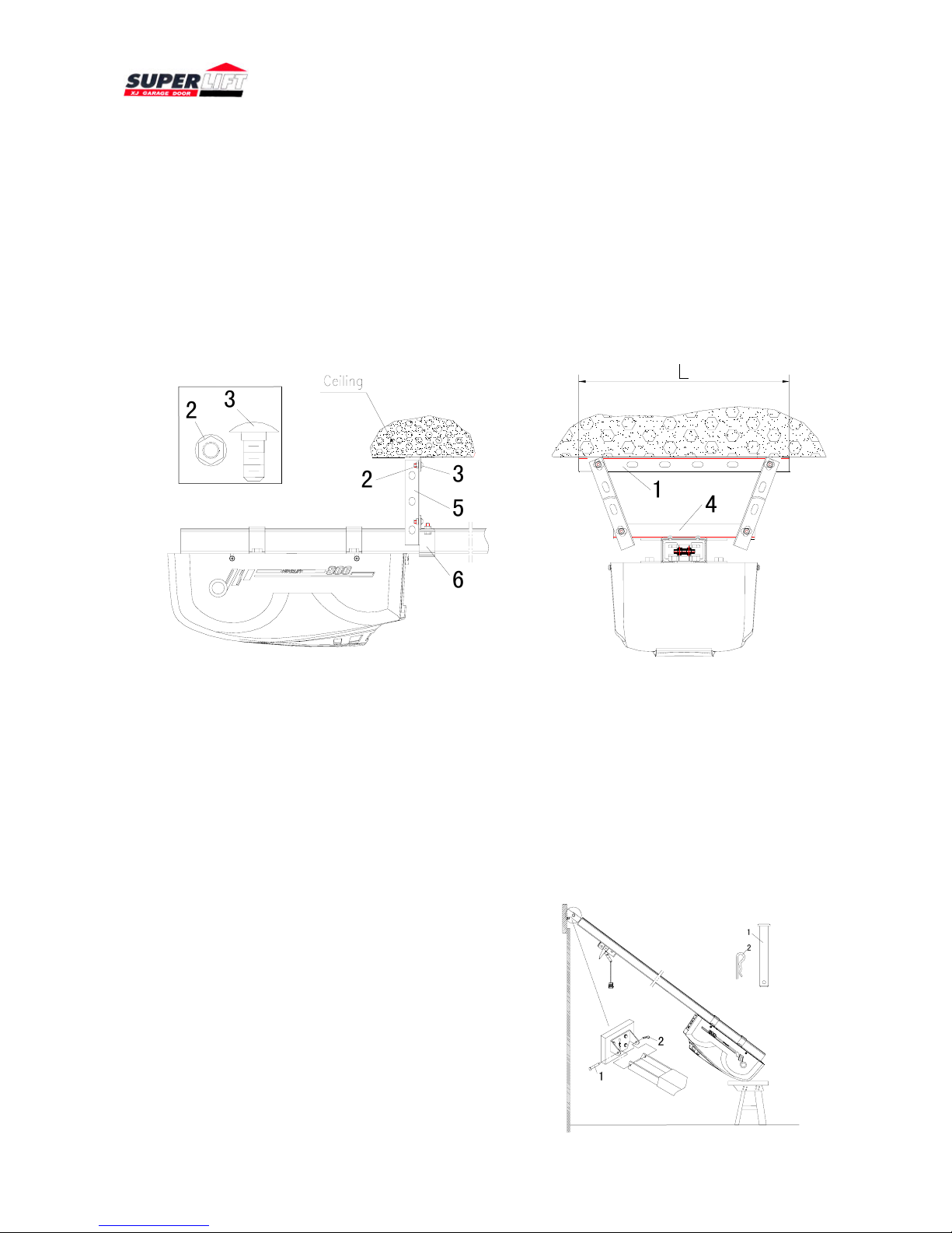
piece of door). The distance from horizontal position of door bracket to door header should be
30mm-50mm and not lower than contact roller height
of door top bracket, use No.3 (four self-drill screws)
to install the door bracket. (As Figure 7)
Note: If the installation hole is not provided, the
electric hand drill can be used to drill four holes, the
diameter is no more than 5mm. If there is no
correspondent support on the door center, the support
board must be added to ensure the installation
strength of door bracket.
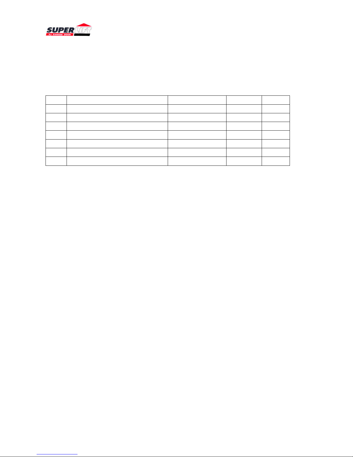
3.4.5. Installation drawbar
Close the door, pull down handle of No.1 (clutch), and make the carriage close to the door
according to the Figure direction (As Figure 8).
Please pay attention to that the horizontal
Distance between the carriage and door should be
200mm-300mm. Use twoΦ8x22 pins to plug No.2
(straight drawbar) to the connection hole of No.1
(clutch) and No.5 (bent drawbar) to the connection
hole of No.7 (door bracket) respectively, meanwhile,
use No.6 (double R elastic pin) to connect.
Afterwards, use two No.3 (bolt M8x20) to connect
straight drawbar and bent drawbar, and use No.4
(flange hexagon header nut M8) to lock tightly. Adjusting the rope
length of clutch pull handle, make the height from the clutch handle to
the ground not less than 1.8 meter. A is the connecting point of emergency lock rope.
4. Adjustment instruction
4.1. Switch on power
Installation socket and wiring must be operated by professional electrical technician. The socket
installation position should be within one-meter distance from the opener header.
Note: the installation and wiring must comply with the architectural working standard and
electrical rules.
4.2. Manipulation instruction
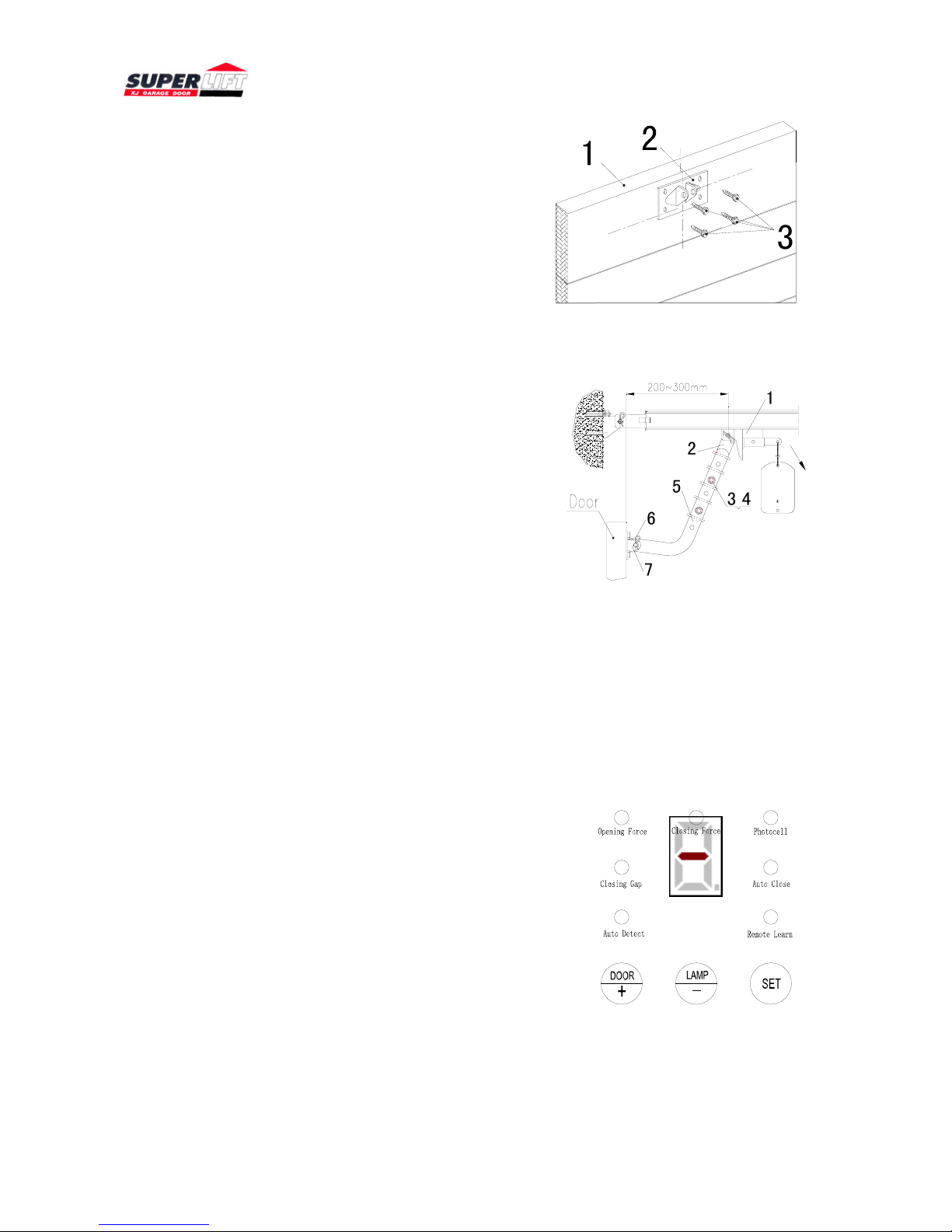
S66 opener adopts with 7 LBD and one digital tube
to display all information. (As figure 9) In ready status,
the digital tube could twinkle with “-”, it indicates the
position of the door: Top indicates opening position;
middle indicates position between opening and closing;
bottom indicates closing position. While running, the
digital tube could flash quickly with “-”.
In ready status, press button “set”, it going into
debugging Status, LBD indicates the present setting sort, digital tube
indicates the value. Press button “set” continuously, you could choose
the present setting, press “+” or “-” , you could modify the present
value. When the change is finished, press the button “set” again, you could store the present value,
and it goes into the next setting automatically. If the present setting is the last Setting, when you
Figure 7
Figure 8
Figure 9
1
3
EMERGENCY RELEASE
CAUTION:
If possible, use the emergency release only
when the door is closed. Be careful when
using the release with the door open beca
-use weak or broken springs may allow the
door to fall rapidly, which can cause serious
injury or death.
Do not use the emergency release rope to
open or close the door.
7
6
1
2
3
4
5