Superlift SDO-5 DC FS 1000 Mounting instructions


Important Safety Recommendations ………………….………………………. 3
Warranty Exclusions ……………………….……………………………………………………………. 4
Technical Specifications …………………................................................................ 5
Assembly Instructions …………......................................................................... 6
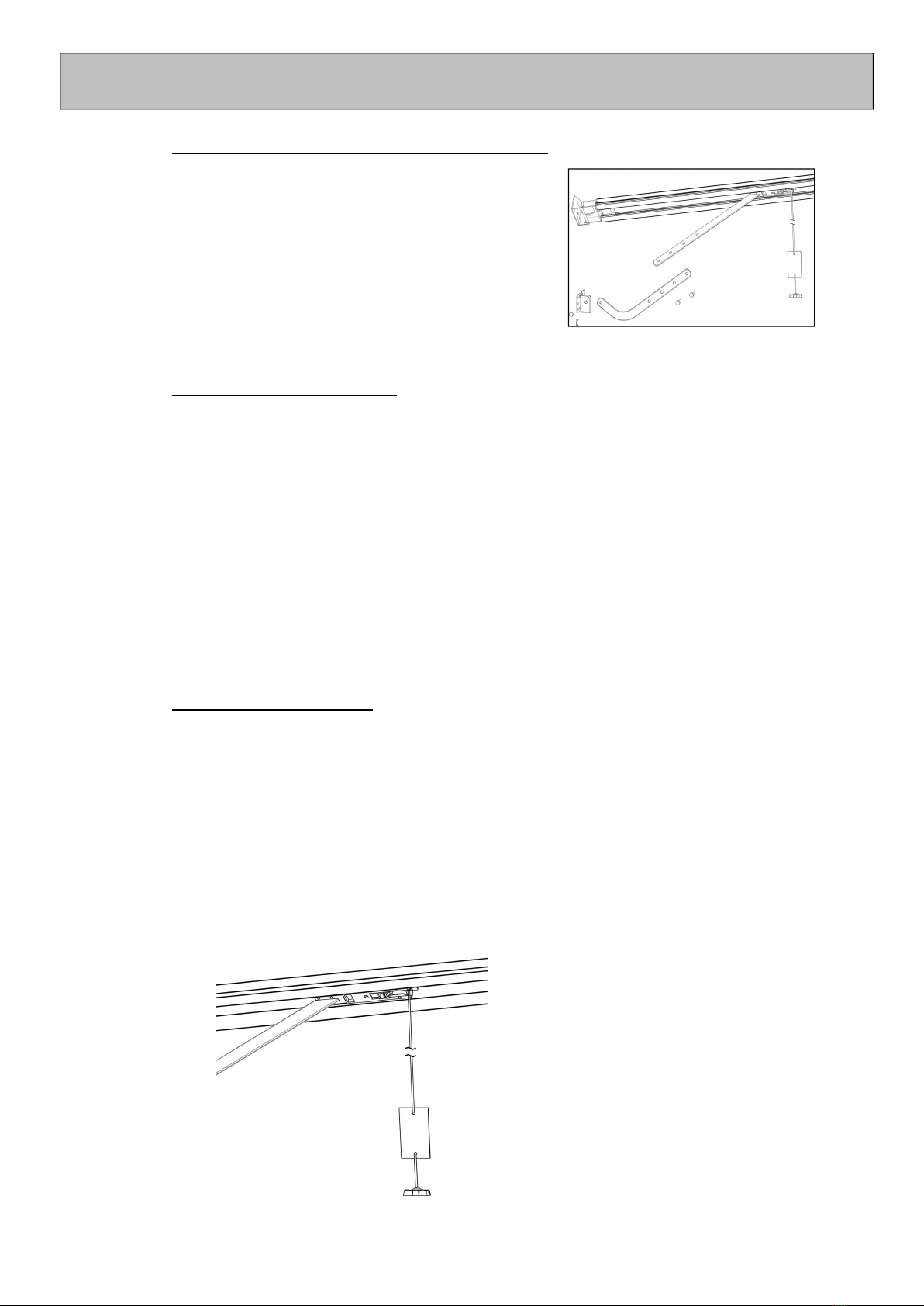
Assembling Drive Rail to Power Head ……………………………………………………………. 6
Drive Rail Hanger Options …….…………………………………………………………………… 6
Drive Belt Tensioning ………………………………………………………………………………… 6
Installation Instructions ………………..................................................................... 7
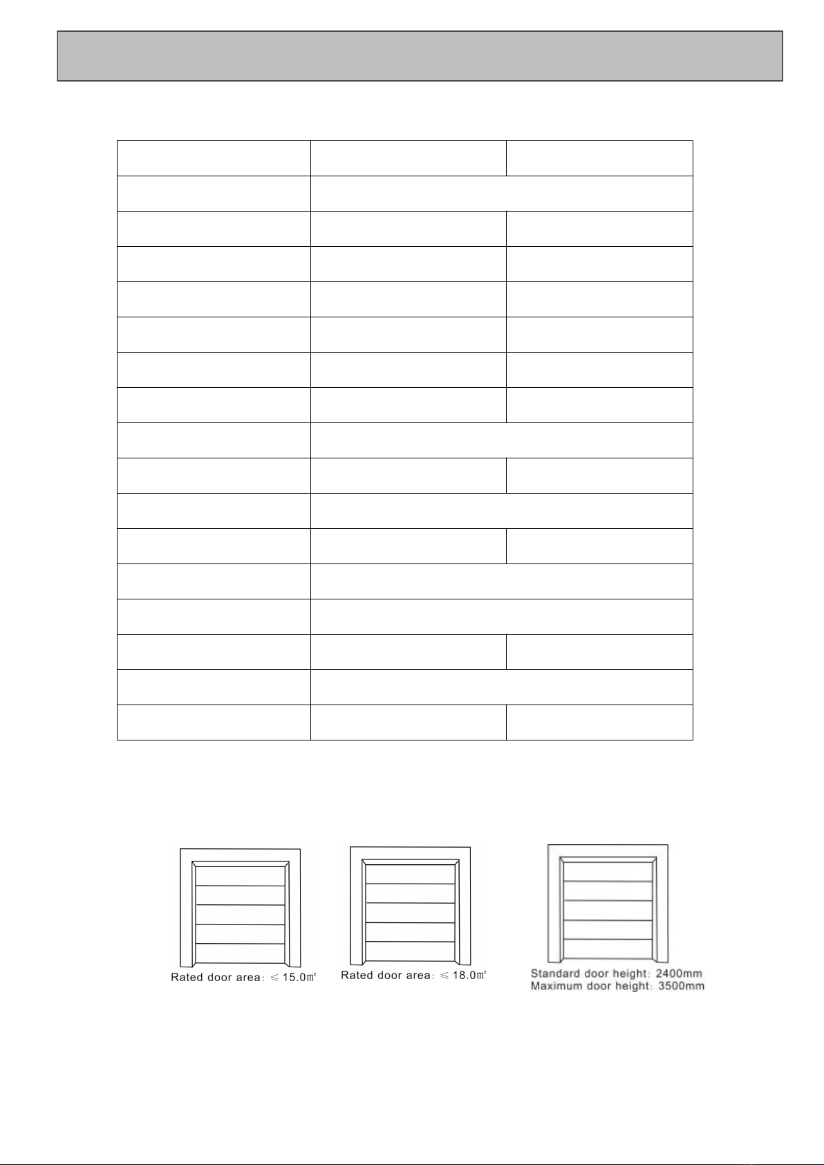
Identifying Garage Door Type ………………………………………………………………. 7
Mounting Header and Door Bracket …………………………………………………………….. 7
Attaching Drive rail to Header Bracket …………………………………………………………….. 8
Attaching Power Head to Ceiling ……………………………………………………………………. 8
Mounting Connecting Arms to Carriage and Door …………………………………………. 9
Disengaging the Garage Door …………………………………………………………………….. 9
Engaging the Garage Door ……………………………………………………………………………. 9
Settings and Adjustments (Programming the Operator) .......................... 10
Preparation ………………………………………………………………………………………… 10
Coding and Deleting Transmitters …………………………………………………………………….. 10
Setting Door Travel …………………………………………………………………………………………. 11
Adjusting Safety Force Sensitivity and Testing …………………………………………………. 11
Setting Travel Speed ………………………………………………………………………………………….. 11
Auto Close Settings ………………………………………………………………………………………….. 12
Auto Close Door Position Setting ………………………………………………………………………. 12
LED Time Setting …………………………………………………………………………………………… 12
Auto Reverse Height Setting ……………………………………………………………………………… 13
Setting Partial Opening Height ………………………………………………………………………. 13
Code Four Buttons to One Door Setting …………………………………………………………. 13
Transmitter Quantity Setting ……………………………………………………………………………… 14
Auto Reverse Ignore Setting (For European Customers) …………………………………….. 14
Pedestrian Door in Garage Door Setting (For European Customers) ………………… 14
Installation, Enabling and Testing Safety Beam Function …………………………………….. 15
Maintenance Alarm Setting ……………………………………………………………………………… 16
Run Button Function …………………………………………………………………………………………… 16
Transmitter Battery Replacement ………………………………………………………………………. 16
Wall Switch (Wireless) ……………………………………………………………………………………. 16
Wall Switch (Wireless) Battery Replacement ………………………………………………….. 16
Output Terminals …………………………………………………………………………………. 17
Installation of Wall Switch …………………………………………………………………………….. 17
Accessories …………………………………………………………………………………………………….. 17
Parts List …………………………………………………………………………………………………….. 18
Trouble Shooting Guide …................................................................................. 19
Notes ……………………………………………………………………………………………………………. 20
CONTENTS

FAILURE TO COMPLY WITH THE FOLLOWING SAFETY RECOMMENDATIONS MAY
RESULT IN SERIOUS PERSONAL INJURY, DEATH AND/OR PROPERTY DAMAGE.
READ AND FOLLOW ALL SAFETY AND INSTALLATION INSTRUCTIONS CAREFULLY.
1. The installation of your new Automatic Garage Door Opener (herein after referred to as
“AGDO”) must be carried out by a technically qualified or licensed person. Attempting to
install your new AGDO without suitable technical qualification may result in severe personal
injury, death and/or property damage.
2. Only install the AGDO on a properly balanced and aligned, well functioning Garage Door. An
improperly balanced or malfunctioning Garage Door could cause serious injury. Have a qualified
person check and if required, make repairs to your Garage Door before installing the AGDO. As
a rule, your Garage Door is deemed to be well balanced and aligned if it:
a. requires an equivalent amount of applied force to manually open or close and,
b. requires no more than 150N of applied force to either manually open or close and,
c. does not rise or fall more than 100mm when stopped at any position between fully open
or fully closed positions and,
d. does not rub on or make contact with any supporting or surrounding structures.
3. Repairs to Garage Doors must only be carried out by technically qualified persons. Attempting
to repair the Garage Door without suitable technical qualification may result in severe personal
injury, death and/or property damage.
4. Remove or render inoperative all existing locks and ropes prior to installation of the AGDO.
5. The counter balance springs on sectional type doors must be properly lubricated between all
the coils with heavy automotive bearing grease. Failure to adequately lubricate the springs may
result in one or more of the following symptoms:
a. The springs will become rusty over time resulting in extra operating friction between the
coils which may cause the AGDO to malfunction
b. Seasonal temperature changes may cause the Garage Door springs to expand and/or
contract. The resultant increase and/or decrease in operating friction may cause the
AGDO to malfunction. Properly lubricating the springs will help to minimize the effect of
seasonal temperature changes in operating friction of your Garage Door.
6. If possible, install the AGDO at least 2 meters or more above the ground. Adjust the Manual
Release Chord so that it hangs approximately 1.8 meters from the ground.
7. Do not connect the AGDO to the power source until this manual instructs you to do so.
8. The AGDO must be connected to a properly earthed general purpose 240V outlet which has
been installed by a qualified electrical contractor.
9. Locate the wall control panel/push button:
a. within site of the Garage Door
b. at a minimum height of 1.5 m above the ground so that it remains out of the reach of
small children
c. away from all moving parts of the door.
10. Install the Entrapment Warning Label in a prominent position next to the wall control button.
11. The Manual Release Instruction Tag must remain attached to the Manual Release Chord.
12. After installing and correctly adjusting the AGDO, the Garage Door must stop and reverse
direction when it comes into contact with a 35mm high solid object placed on the floor under
the Garage Door.
13. The correct function of the Safety Obstruction Reversing System should be checked monthly.
Make sure that the Garage Door reverses when it makes contact with an obstruction.
IMPORTANT SAFETY RECOMMENDATIONS

14. Never use the AGDO unless the Garage Door is in full view and free from objects such as cars,
children and/or adults.
15. Never allow children to operate the AGDO.
16. Never operate the AGDO when children/persons are under or near the path of the door.
Children must always be supervised when near the Garage Door and when the AGDO is in use.
17. Never attempt to disengage the AGDO to manual operation when there are children/persons or
and other objects including motor vehicles under or near the path of the Garage Door.
18. Never attempt to open or close the Garage Door by pulling on the Manual Release Chord.
19. Never attempt to make any repairs or remove covers from the AGDO without first
disconnecting the power supply chord from main power supply.
20. For additional safety we strongly recommend the fitment of Safety Beams. Although the AGDO
incorporates a pressure sensitive safety obstruction system, the addition of Safety Beams will
greatly enhance the operating safety an Automatic Garage Door and provide additional peace
of mind. In some countries it is mandatory by law to fit Safety Beams. It is the sole
responsibility of the owner/installer to fit Safety Beams in those countries which so require.
21. Removal of the AGDO’s protective covers must only be performed by a technically qualified
person. Attempting to remove the protective covers or repair the AGDO without suitable
technical qualification may result in severe personal injury, death and/or property damage.
22. Always ensure that the Garage Door is fully open before driving into or out of the Garage.
23. Always ensure the Garage Door is fully closed before leaving the driveway.
24. Adjustments to the Safety Obstruction Force settings must only be carried out by a technically
qualified person. Attempting to adjust the Safety Reverse Force setting without suitable
technical qualification may result in severe personal injury, death and/or property damage.
25. Always Keep hands and loose clothing clear of the Garage Door and Product.
26. For the Safety Obstruction Force System to function it must first encounter an object/person on
to which some force MUST be exerted. As a result, the object/person/door may suffer
DAMAGE OR INJURY.
27. The Safety Obstruction Force System is designed to work on STATIONARY objects only. If the
Garage Door encounters a moving object during an Open or Close Cycle, serious personal
injury, death and/or property damage may occur.
Warranty Exclusions
No claims whatsoever will be recognized under the terms of this product’s warranty which
pertain to damage, injury, cost or expense, suffered by persons or to property, which either
directly or indirectly arise out of any of the following actions;
a. Failure to install the AGDO in accordance with the installation instructions herein
contained.
b. The Garage Door striking a moving object. (refer to item 27 above)
c. The AGDO being used on other than a maximum 4 car residential application.
d. Failure to adequately lubricate the Garage Door counter balance springs. (refer point 5
in the above)
e. Attempting to open or close the Garage Door by directly pulling on the Manual Release
Chord.
f. Installing the AGDO on an improperly balanced and/or poorly functioning and/or miss
aligned Garage Door. (refer to item 2 above)
g. Manually releasing the Garage Door in any position other than when fully closed.
h. Failure to connect the AGDO to a properly earthed power supply.
IMPORTANT SAFETY RECOMMENDATIONS

FS 1000
FS 1200
Input Voltage
220 - 240V / 110 - 127V, 50–60 Hz
Maximum Lift Force
1000 N
1200 N
Maximum Door Area
15.0 ㎡
18.0 ㎡
Maximum Door Weight
100 kg
130kg
Maximum Door Height
3500mm
3500mm
Drive Rail
Belt
Belt
Opening / Closing Speed
128 - 160mm / Second
L.E.D
24V / 15 LED bulbs
Limit Setting
Electronic
Electronic
Transformer
Overload protection technology
Transmitter Frequency
433.92 MHz
433.92 MHz
Coding Format
Rolling code (7.38 x 10¹⁹ Combinations)
Code Storage Capacity
50
Working Temperature
-40℃- +50℃
-40℃- +50℃
Safety Protection
Auto Reverse, PE Beams Option, Flashing Light Option
Protection Level
IP20
IP20
FS 1000
FS 1200
TECHNICAL SPECIFACTIONS

1. Assembling Drive Rail to Power Head
1.1 On a clean, smooth surface, unpack the Drive Rail, Power Head and two “U” type brackets
with Nyloc Nuts as shown in (Fig.1)
1.2 Align and insert the rail onto drive shaft.
1.3 Attach the two “U” type brackets over the rail and secure to the motor head with the M6
Nyloc Nuts provided. (Fig.1)
2. Drive Rail Hanger Options
2.1 Option One: Cut down perforated strapping for the correct height to ceiling. Attach
perforated strapping using M8 nut and bolt provided at motor head end. Strapping may be
moved along opener chassis to find best fixing point for ceiling studs.
2.2 Option Two: Twist on bracket provided may also be used as in option one. This bracket may
also be used in any position on the drive rail. More than one may be used in various
positions on longer rails for added stability.
3. Drive Belt Tensioning
3.1 Tighten tensioner adjusting nut, pictured (Fig.2) until the Drive Belt has approximately 3 ~ 5
mm of sag at the mid-point of the drive rail.
3.2 Ensure the drive belt has not been over tightened as this will cause premature wear of the
drive shaft and front adjusting pulley wheel.
Fig. 2
Fig. 1
ASSEMBLY INSTRUCTIONS

4 Identifying Garage Door Type
4.1 From the diagrams depicted in Fig.3 select the type of installation that is suited to your
Garage Door type.
5. Mounting Header and Door Bracket
5.1 Find the highest point in travel of the Garage Door and mark this as a horizontal line on the
Header above the top edge of the Garage Door.
5.2 Find the Garage Door Center Line and with a pencil, mark a vertical line on the Header above
the top edge of the Garage Door.
5.3 Centralize the bottom edge of the Header Bracket at no more than 50mm above the marked
out vertical and horizontal lines and mark the location of at least 2 screw holes.
5.4 Drill the 2 screw holes and use 2 screws to secure the Header Bracket to the Header.
5.5 Important Note: The Header Bracket carries ALL the opening and closing thrust and as
such must be securely fastened to a rigid, structural member of the garage.
5.6 Find the Garage Door Center Line and affix the Garage Door Bracket on to a structural
member of the Garage Door. Mark the location of at least 2 screw holes as far apart from
each other as possible.
5.7 Drill the 2 screw holes with appropriate drill and securely mount the Garage Door Bracket to
the Garage Door using 2 screws.
5.8 Important Note: It is recommended to use screws with nuts rather than self drilling
screws.
5.9 Important Note: For Sectional Doors, the pivot point of the Garage Door Bracket should be
mounted approx. one third down from the top edge of the top panel. For Tilt doors the
pivot point should be as close to the top edge of the Garage Door as possible.
Installation to jamb-type fittings
Use straight door arm only
Door Bracket
Installation to jamb-type fittings
Mount door bracket approx.
1/3 Of the way down from the
top panel. Curved door arm
must be used and connected
to door with straight arm
connected to carriage
Fig
3
Installation to track-type fittings
Use straight door arm only
Fig. 4
INSTALLATION INSTRUCTIONS

6. Attaching Drive Rail to Header Bracket
6.1 Lay the assembled AGDO on the floor in line with the centerline of the Garage Door so that
the Power Head is furthest from the Garage Door.
6.2 Lift the Drive Rail up to the Header Bracket so that the Terminal Bracket sits in between the
ears of the Header Bracket (Fig.5)
6.3 Align the mounting holes and fully insert the Long Clevis Pin provided
6.4 Secure the Clevis Pin with the Spring Clip provided.
7. Attaching Power Head to Ceiling
7.1 Raise the Power Head off the floor and rest it on a support high enough that the Drive Rail
runs parallel to the ground. (Fig.6 depicts typical Sectional type Garage Door installation)
7.2 Carefully open the Garage Door and ensure that no part of it comes into contact with the
Drive Rail or the Power Head during the entire movement of the Garage Door.
7.3 Align the Drive Rail with the centerline of the Garage Door and securely fasten the Power
Head to a structural member of the ceiling or roof using appropriate hanging material.
(Fig.6)
7.4 The hanging material should be attached to the opener chassis, or the twist on bracket or
both if both are used.
7.5 Once mounted the Power Head and Drive Rail should be sitting parallel to the floor along
both planes. (for Sectional and Track-Type Tilt Doors only! For jamb-type Tilt Door refer to
Fig.3)
7.6 Important Note: With the Garage Door in the fully open position, the underside of the
Drive Rail should be no more than 50 mm above the highest arcing point of the Garage
Door for its entire length. (Fig.6)
Fig
5
50mm or
Less
Fig
6
INSTALLATION INSTRUCTIONS

8. Mounting Connecting Arms to Carriage and Door
8.1 Close the Garage Door with the Carriage disengaged.
8.2 Attach the Bent Connecting Arm to the Door Mounting
Bracket using the Clevis Pin provided. (Fig.7)
8.3 Bring the Straight and Bent Connecting Arms together
and align the 2 closest sets of holes.
8.4 Using 2 of the 8 mm bolts and nuts provided, securely
fix the Bent and Straight Connecting Arms together.
9. Disengaging the Garage Door
9.1 To disengage the AGDO from the Garage Door, pull down on the disengage chord. (Fig.8)
9.2 The rail has punched holes to lock the door while in manual mode.
9.3 Important Note: Never attempt to open or close the Garage Door by pulling on the
Disengage Chord. Doing so may result in SERIOUS PERSONAL INJURY and/or PROPERTY
DAMAGE.
9.4 Important Note: Always disengage the AGDO with the Garage Door in the fully closed
position.
9.5 Important Note: If attempting to disengage the AGDO from any position other than with
the Garage Door fully closed ensure that there are no persons and/or property near or
directly under the path of the door.
10. Engaging the Garage Door
10.1 Pull down the disengage chord and open the Garage Door by hand so that it is approx.
one meter off the ground.
10.2 Push back the release lever and press the hand transmitter.
10.3 After a short time, the AGDO will self-engage into the Carriage.
10.4 Important Note: If the AGDO runs for some time (first cycle) and then stops without
engaging into the Carriage press the hand transmitter again and it will self-engage on
the second cycle.
Fig. 8
Fig. 7
INSTALLATION INSTRUCTIONS

Programming the Operator
11. Preparation
11.1 Make sure the carriage is locked into automatic mode. Lift and lower the door by hand to
confirm the carriage is locked onto the belt connector.
11.2 Connect the AGDO to a properly earthed power supply using the power chord provided.
Make sure that no excess chord hangs below the AGDO when it is plugged in.
11.3 Switch the power on at the power supply. The courtesy light will glow for several seconds.
At the same time the LED display will flash various sequences until it stops at two vertical
lines “11”. When the screen shows “11“ the opener is in standby. (fig.10)
11.4 Note: When in standby, a short press of the “Set” button will clear all error and alarms,
and then return to standby.
11.5 When in settings a short press of the “Code” button will return to standby.
11.6 A long press of the “Set” button will put the AGDO in “Program” mode.
11.7 A long press of the “Down” button will restore factory settings.
12. Coding and Deleting Transmitters
12.1 This AGDO will store 5 to 50 transmitter codes. When the AGDO is full, the LED display
will flash “F”.
12.2 To code a new transmitter, momentarily press the “Code” button. A red dot “.” will be
displayed on the LED screen. Momentarily press the button you wish to code on the
transmitter. Momentarily press the same button on the transmitter a second time. The
dot will flash on the LED display then change to standby. This indicates the transmitter
code is now stored.
12.3 To code additional transmitters repeat step 12.2.
12.4 To delete codes from the AGDO press and hold the “Code” button for approx. 6 seconds.
“C” will display on the LED screen indicating all transmitter codes have been deleted.
SETTINGS & ADJUSTMENTS
Fig. 10
Fig. 9

13. Setting Door Travel
13.1 Press and hold the “Set” button until “1” is displayed on the LED screen. (Fig.11)
13.2 Momentarily press the “Set” button. “n” will be displayed on the LED screen.
(Fig.12) Press and hold the “Up” button. The door will begin to travel in the
open direction. The “Opening Indicator” light will begin to flash. Release the
button when door reaches desired open position. Fine tuning the door height is
possible using the “Up” or “Down” buttons.
13.3 Momentarily press the “Set” button. “u” will be displayed on the LED screen.
(Fig.13) Press and hold the “Down” button. The door will begin to travel in the
close direction. The “Closing Indicator” light will begin to flash.
Release the button when the door reaches the desired close position.
Fine tuning the close position is possible using the “Up” or “Down” buttons.
13.4 Momentarily press the “Set” button again to confirm the close limit.
13.5 The door will now open and close automatically for one cycle to map the open
and close sensitivity force requirements.
13.6 “11” will be displayed to show door travel settings are complete. (Fig.11)
14. Adjusting Safety Force Sensitivity
14.1 Press and hold the “Set” button until “1” is displayed on the LED screen (Fig.11)
14.2 Momentarily press the “UP” button until “2” is displayed on the LED screen (Fig.14)
14.3 Momentarily press the “Set” button until the factory setting of “3” is displayed on the LED
screen.
14.4 Press “UP” to increase force and “Down” to decrease force.
14.5 Force range is 1 to 5.
14.6 Momentarily press “Set” to confirm your force setting.
15. Setting Travel Speed
15.1 Press and hold the “Set” button until “1” is displayed on the LED screen (Fig.11)
15.2 Momentarily press the “Up” button until “3” is displayed on the LED screen (Fig.15)
15.3 Momentarily press the “Set” button. “A” will be displayed on the LED screen. (Fig.16)
Note: “A” is full speed. 160mm per second.
15.4 To reduce speed to 80% of full speed (128mm per Second) momentarily press the “Down”
button. “8” will display on the LED screen.
15.5 Momentarily press the “Set” button to confirm the change of speed.
15.6 Important Note: If a speed change is performed, you must reset door travel.
SETTINGS & ADJUSTMENTS
Fig. 12
Fig. 13
Fig. 11
Fig.14
Fig.15
Fig.16

16. Auto Close Mode
16.1 In Auto Close Mode the AGDO will automatically close at a preset time after it reaches
the fully open position.
16.2 To enable the Auto Close function press and hold down the “Set” button until “1” is
displayed on the LED screen. (Fig.11)
16.3 Momentarily press the “Up” button until “4” is displayed on the
LED screen. (Fig.4)
16.4 Momentarily press the “Set” button which will show the current
Auto Close setting.
16.5 Settings are “0” (Off) up to “9”. Each number above zero is a 15 second
increment. e.g. “2” Auto close after 30 seconds.
16.6 Momentarily press the “Set” button to confirm your setting.
16.7 Important Note: Auto Close Mode will only work if Safety Beams have been enabled
and correctly aligned.
17. Auto Close Door Position Setting
17.1 With Auto Close Door Position Mode the AGDO has the option of closing from any open
position or from the fully open position only. This gives you the option of overriding Auto
Close if the door is not in the fully open position.
17.2 To enable the Auto Close Door Position function press and hold down the “Set” button
until “1” is displayed on the LED screen. (Fig.11)
17.3 Momentarily press the “Up” button until “5” is displayed on the LED screen. (Fig.18)
17.4 Momentarily press the “Set” button which will show the current Auto Close Door Position
setting.
17.5 Setting “1” means the door will only Auto Close from the fully open position.
17.6 Setting “2” means the door will Auto Close from any open position.
17.7 Momentarily press the “Set” button to confirm your selection.
17.8 Note: Setting “1” is the factory setting.
18. LED Time Setting
18.1 The LED Time Setting allows you to change the length of time the AGDO LED courtesy
light will stay on before automatically switching off.
18.2 To change the LED Time Setting press and hold down the “Set” button until “1” is
displayed on the LED screen. (Fig.11)
18.3 Momentarily press the “Up” button 5 until “6” is displayed on the LED screen. (Fig.19)
18.4 Momentarily press the “Set” button which will show the current LED delay time.
18.5 Note: Factory set at 3 minutes. “3”.
18.6 Settings are “1” (Off) up to “9”. Each number is a minute
increment. e.g. “2” LED will turn off after 2 minutes.
18.7 Momentarily press the “Set” button to confirm your selection.
SETTINGS & ADJUSTMENTS
Fig.17
Fig.18
Fig.19

19. Auto Reverse Height Setting
19.1 Auto Reverse Height Setting allows the AGDO to Auto Reverse to a preset height.
19.2 To change the Auto Reverse Height Setting press and hold down the “Set” button until
“1” is displayed on the LED screen. (Fig.11)
19.3 Momentarily press the “Up” button until “7” is displayed on the LED screen. (Fig.20)
19.4 Momentarily press the “Set” button which will show the current Auto Reverse Height
Setting.
19.5 Settings are “0” up to “9”. Each number above zero is a one tenth increment of the full
height of the door. e.g. a 2 meter door set to “2” will Auto
Reverse 400mm only.
19.6 Momentarily press the “Set” button to confirm your selection.
19.7 Note: Factory setting is “0” which is full height Auto Reverse.
20. Setting Partial Opening Height
20.1 Partial Opening Height sets 2 buttons on the remote to open the
AGDO to either full height or an adjustable height.
20.2 To enable Partial Height function press and hold down the “Set”
button until “1” is displayed on the LED screen. (Fig.11)
20.3 Momentarily press the “Up” button until “8” is displayed on the LED screen. (Fig.21)
20.4 Momentarily press the “Set” button which will show the current Partial Opening Height.
20.5 Settings are “0” (Full Open Height) up to “9”. Each number above zero is one tenth of full
height increment. e.g. a 2 meter door set to “2” Button 2 will open the door to 400mm off
the ground.
21. Code All Buttons to One Door Setting
21.1 In this mode the AGDO will automatically respond to all four buttons on the remote.
21.2 To enable this function press and hold down the “Set” button until “P” is displayed on the
LED screen. (Fig.11)
21.3 Momentarily press the “Up” button until “9” is displayed on the LED screen. (Fig.22)
21.4 Momentarily press the “Set” button which will show the current setting.
21.5 Settings are “0”, only one button on the remote will activate the door. Or “1”, all four
buttons on the remote will activate the door.
21.6 Note: If function “8” (Partial Opening Height) is on,
this function cannot be used. Function “8” will take priority.
SETTINGS & ADJUSTMENTS
Fig.20
Fig.22
Fig.21

22. Transmitter Quantity Setting
22.1 In Transmitter Quantity Mode the AGDO can be programmed to accept from 5 to 50
transmitters.
22.2 To enable the Transmitter Quantity Setting press and hold down the “Set” button until
“1” is displayed on the LED screen. (Fig.11)
22.3 Momentarily press the “Up” button until “A” is displayed on the LED screen. (Fig.23)
22.4 Momentarily press the “Set” button which will show the current Transmitter Quantity
setting.
22.5 Settings are “A” equals 50 transmitters. “1” up to “9”
will go up in increments of 5 transmitters. e.g. “2” will
allow the AGDO to code in 10 remotes.
23. Auto Reverse Ignore Setting (For European Customers)
23.1 In Auto Reverse Ignore Mode the AGDO will ignore the Auto Reverse function for a
maximum height of 90mm. If an object is less than the set ignore height, the door will not
Auto Reverse when it is obstructed.
23.2 Note: e.g. Usually used in areas where there may be a buildup of snow.
23.3 To enable the Auto Reverse Ignore function press and hold down the “Set” button until
“1” is displayed on the LED screen. (Fig.11)
23.4 Momentarily press the “Up” button until “b” is displayed on the LED screen. (Fig.24)
23.5 Momentarily press the “Set” button which will show the current Auto Reverse Ignore
setting.
23.6 Settings are “0” (Off) up to “9”. Each number above zero is a 10mm increment. e.g. “2”
the AGDO will ignore an object up to 20mm high.
24. Pedestrian Door Switch Setting (For European Customers)
24.1 Note: The Pedestrian Door Switch is used on garage doors that have a Pedestrian Door
fitted.
24.2 The Pedestrian Door Switch Setting allows the AGDO to change from a Normally Open
(NO) terminal to a Normally Closed (NC) terminal connection when wiring in a pedestrian
door sensor.
24.3 To change from Normally Open to Normally Closed press and hold down the “Set” button
until “1” is displayed on the LED screen. (Fig.11).
24.4 Momentarily press the “Up” button until “C” is displayed on the
LED screen. (Fig.25)
24.5 Momentarily press the “Set” button which will show the current
Auto Close setting.
24.6 Settings are “0” Normally Open terminal or “1” Normally Closed.
24.7 Note: See “Output Terminals” for wiring connections for this function. (Fig.????)
SETTINGS & ADJUSTMENTS
Fig.23
Fig.24
Fig.25

25. Installation and Enabling of Safety Beams (Optional)
Installation
25.1 Locate the Safety Beam Mounting Brackets provided.
25.2 Mark the inside door framing so that the bottom edge of the Mounting Brackets sits
125mm off the floor.
25.3 Use the 2 mounting screws provided to fasten each Mounting Bracket to the wall. Do not
over tighten the fixing screws as the Mounting Brackets will need to undergo adjustment
later.
25.4 Use the 2 screws and nuts provided to fasten the Safety Beams to the Mounting Brackets
so that the Indicator Lamp on each Safety Beam is facing upwards.
25.5 Using 3 Core Cable, strip back and connect 2 strands to the Emitter and 3 strands to the
Receiver. (Fig.26)
25.6 Securely fix the cable up and along the wall and run one length of each cable adjacent to
the Rear Cover.
25.7 Strip back and connect one strand of each cable to the terminals marked “24V”, “PE” &
“GND”. (Fig.26)
25.8 Note: Superlift Safety Beam kits will have full instructions on mounting and connecting.
Enabling
25.9 To enable safety beam function press and hold “Set” button until “1” is displayed on the
LED screen. (Fig.11).
25.10 Press “Up” button until “d” is displayed on the LED screen.
25.11 Momentarily press the “Set” button. If “0” is displayed photo
beams are not enabled. Momentarily pressing the “Up” button will
change the LED to display “1”. Photo Beams are enabled.
25.12 Initiate a closing cycle on the AGDO and as the Garage Door is closing
pass your hand through the line of the Safety Beams. If the Safety Beams are functioning
correctly the AGDO should stop and then immediately reverse direction.
25.13 If the Garage Door does not commence to close at all, check that the Safety Beams are
aligned correctly.
25.14 Important Note: The AGDO will only support the fitment of Superlift Brand 4 wire
Safety Beams.
25.15 Note: If safety beams are not fitted, ensure that “0” is displayed and safety beam
function is disabled.
SETTINGS & ADJUSTMENTS
Emitter
Receiver
Fig.26
Fig.27

26. Maintenance Alarm Setting
26.1 In Maintenance Alarm Mode the AGDO LED Courtesy Light will automatically start
flashing once a preset number of open/close cycles is reached.
26.2 To enable the Maintenance Alarm function press and hold down the “Set” button until
“1” is displayed on the LED screen. (Fig.11)
26.3 Momentarily press the “Up” button until “E” is displayed on the LED Screen. (Fig.28)
26.4 Momentarily press the “Set” button which will show the current Maintenance Alarm
setting.
26.5 Settings are “0” (Off) up to “5”. Each number above zero is a 1000 cycle increment. e.g.
“2” Maintenance Alarm will start LED Courtesy Light flashing after 2000 cycles.
27. Run Button Function
27.1 The AGDO has a Run Button function.
27.2 To open press the “UP” button. “n” will be displayed on the panel as the door travels to
the open position.
27.3 To close press the “DOWN” button. “u” will be displayed on the panel as the door travels
to the closed position.
28. Transmitter Battery Replacement
28.1 Remove the fixing screws located on the underside of the Hand-Held Transmitter.
28.2 Open the 2 halves of the Transmitter shell and replace the battery with one of identical
specification.
28.3 Test that the Red Coloured Indicator lamp illuminates when one of the Transmitter
buttons is pressed and then replace the fixing screws.
29. Wall Switch - Wireless
29.1 The wireless wall switch provides ease of installation without the need for running hard
wires to the switch and can be mounted in any convenient location.
29.2 The switch can be permanently screwed to the wall through the mounting holes
provided.
29.3 Use the mounting screws provided to fix the Wall Switch to the wall.
29.4 The wireless wall switch may be learned into the AGDO as per the procedure outline in
Sec.12.2, “To code a transmitter”
29.5 Important Note: The wireless Wall Switch must be mounted within sight of the garage
door and a reasonable distance away from moving parts. It should be mounted at least
1500mm above the ground.
30. Wall Switch-Wireless Battery Replacement
30.1 Remove the cover plate while the unit is still mounted to the wall by sliding and twisting a
straight screwdriver in the slot provided on the top and underside of the wall plate.
30.2 Use a small Phillips Head Screwdriver remove the 4 screws holding the switches in place.
30.3 Replace the battery with one of identical specification.
30.4 Test that the Red Coloured Indicator lamp illuminates when one of the Transmitter
buttons is pressed and then replace the fixing screws and cover plate.
SETTINGS & ADJUSTMENTS
Fig.28

31. Output Terminals
31.1 There are 5 main functions supported by the output terminals of the AGDO. (Fig.29)
31.2 Pedestrian Door Switch. This ensures the garage door will not open if the pedestrian door
is not in a locked position.
31.3 PE Beam function works when Photo Electric Safety Beams are fitted.
31.4 The O/S/C, Open/Stop/Close terminals are used with normally opened switch and
function like run button. May also be used with universal receivers
31.5 +24V terminal when used with the GND terminal will power after market accessories.
e.g. universal receivers.
Safety Photo Electric Beams Wall Switch-Wireless, 2 Button
Universal Receiver Wall Switch-Wireless, 4 Button
Wireless keypad Entry Battery Backup
4 Button Remote Hand Transmitter (SDO-3) Phone App Receiver
4 Button Remote Hand Transmitter TX-4
OUTPUT TERMINALS
ACCESSORIES
Fig.29

Item
Qty
Description
1
1
L.E.D Cover
2
1
Control Panel Cover-1
3
1
Control Panel Cover-2
4
1
Main Cover
5
1
L.E.D Light
6
1
Min Logic Board
7
1
Control Logic Board
8
1
DC Motor
9
1
Motor Shaft Adaptor
10
1
Transformer
11
1
Transformer Plate
12
1
Chassis
Item
Qty
Description
25
1
Straight Arm
26
1
Belt Connection
27
1
Caution Card
28
1
Release Handle
29
2
Transmitter
30
1
Transmitter Bracket
Item
Qty
Description
13
1
Sprocket Assembly
14
2
U Hanging Bracket
15
1
Twist on Bracket
16
1
C rail – Steel
17
2
Mounting Bracket
18
1
Belt Adjuster Wheel
19
1
Belt Adjuster Bracket
20
1
Ending Bracket
21
1
Wall Bracket
22
1
Door Bracket
23
1
Bent Arm
24
1
Carriage Assembly
SPARE PARTS

Symptom
Possible Cause
Remedy
Opener not working
LED lights are dim
Mains power not turned on
Garage door obstructed
Turn on mains power
Check for obstruction
Door stops during open cycle before
reaching the fully open position
Garage door may be obstructed
Garage door springs may have lost tension
Safety force sensitivity may need adjustment
Disengage opener and check door is running freely
Call Serviceman for repair or service
Refer item 14
LED courtesy light stays on
LED courtesy light won’t come on
Logic board may be faulty
LED light strip may need replacing
Call a serviceman to check and repair
Door will not reverse on hitting an object
Safety force sensitivity may be set too high
and will require adjustment
Refer item 14
Door moves down then auto reverses
back to open position
Safety force sensitivity maybe set too low and
will require adjustment
Refer item 14
The door operates from push button
function on opener but not from hand
transmitters
Transmitter is damaged or broken
Transmitter code is not programmed
Flat battery
Try an alternative transmitter
Code transmitter. Refer item 12
Replace Battery. Refer item 28
Door stops before reaching open or close
position
Door travel may need adjustment
Refer item 13
Drive belt rubbing in track
Belt has lost tension and requires adjustment
Refer item 3
Transmitter range is low
Flat battery
Antennae wire broken
Replace battery. Refer item 28
Check for visible sign that antenna is still in tact
The remote control cannot be used or the
operation distance is short
1. Flat battery
2. Antenna is loosed or not well extended
3. Interference around nearby
1. Replace new battery
2. Extended the antenna on the opener
3. Get rid of interference
Digital displays error code
Transmitter storage full
Delete all codes
Reset transmitter quantity setting. Refer item 22
The opener is operating but the door is
not moving
Motor shaft may be worn
Opener is manual mode
Call a serviceman to check and repair
Re-engage opener. Refer item 10
Digital displays error code
The opener has detected the door requires
scheduled service
Call a service for your regular service
TROUBLE SHOOTING GUIDE
This manual suits for next models
1
Table of contents
Other Superlift Garage Door Opener manuals
Popular Garage Door Opener manuals by other brands

Label
Label ETERNA 90 installation manual

Keyautomation
Keyautomation Revo+ Instructions and warnings for installation and use

Entrematic
Entrematic Ditec LUXO Series Technical manual

Keyautomation
Keyautomation SC122 Instructions and warnings for installation and use

Merlin
Merlin CYCLONE PRO MT120EVO Installation and operating instructions

DITEC
DITEC DAB305 user manual