Supermicro PWS-1k62A-1R Owner's manual

Information for Lot 9 of ErP (Ecodesign)
This addendum addresses European Union (EU) Ecodesign requirements for servers and storage
products. All data and ratings within this addendum are in reference only to the Supermicro product(s) in
the manual. The below information conforms to requirements laid down in Annex II of the Commission
Regulation 2019/424.
3(1)(a): See Section 1.1 of the system manual for the product type.
3(1)(b): See the title page and preface of the system manual for the trademark and
manufacturer’s address.
3(1)(c): See the title page of the system manual for product model number(s).
3(1)(d): See the serial number on the physical system to determine the year of manufacture.
3(1)(e-j): PSU Efficiency and Power Factor Value (Table) (From 80 Plus report)
PSU Model #: PWS-1k62A-1R
Watts: 1600 PSU Efficiency
Power Factor
% of Rated Load
10 % 20 % 50 % 100 %
50 %
Single Output (AC-DC)
91.88 % 94.24 % 96.33 % 93.93 %
0.99
System (EUT) Efficiency in Idle State Power (Table)
Representative
Configurations
Measured Idle State
Power (W)
Calculated Idle Power
Allowance (W)
High-End Performance
Configuration
354.5
479.7
Typical Configuration
N/A
N/A
Low-End Performance
Configuration
326.3
342.6
System (EUT) Efficiency in Active State Power (Table)
Representative
Configurations
Active State
Efficiency Score
(Effserver)
Minimum Active State
Efficiency for 2-Socket
Server
High-End Performance
Configuration
44.7
Typical Configuration
N/A
9.5
Low-End Performance
Configuration
24.8

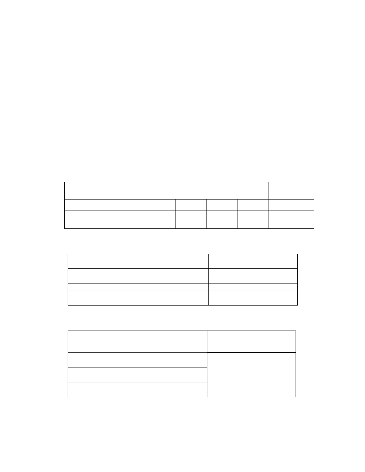
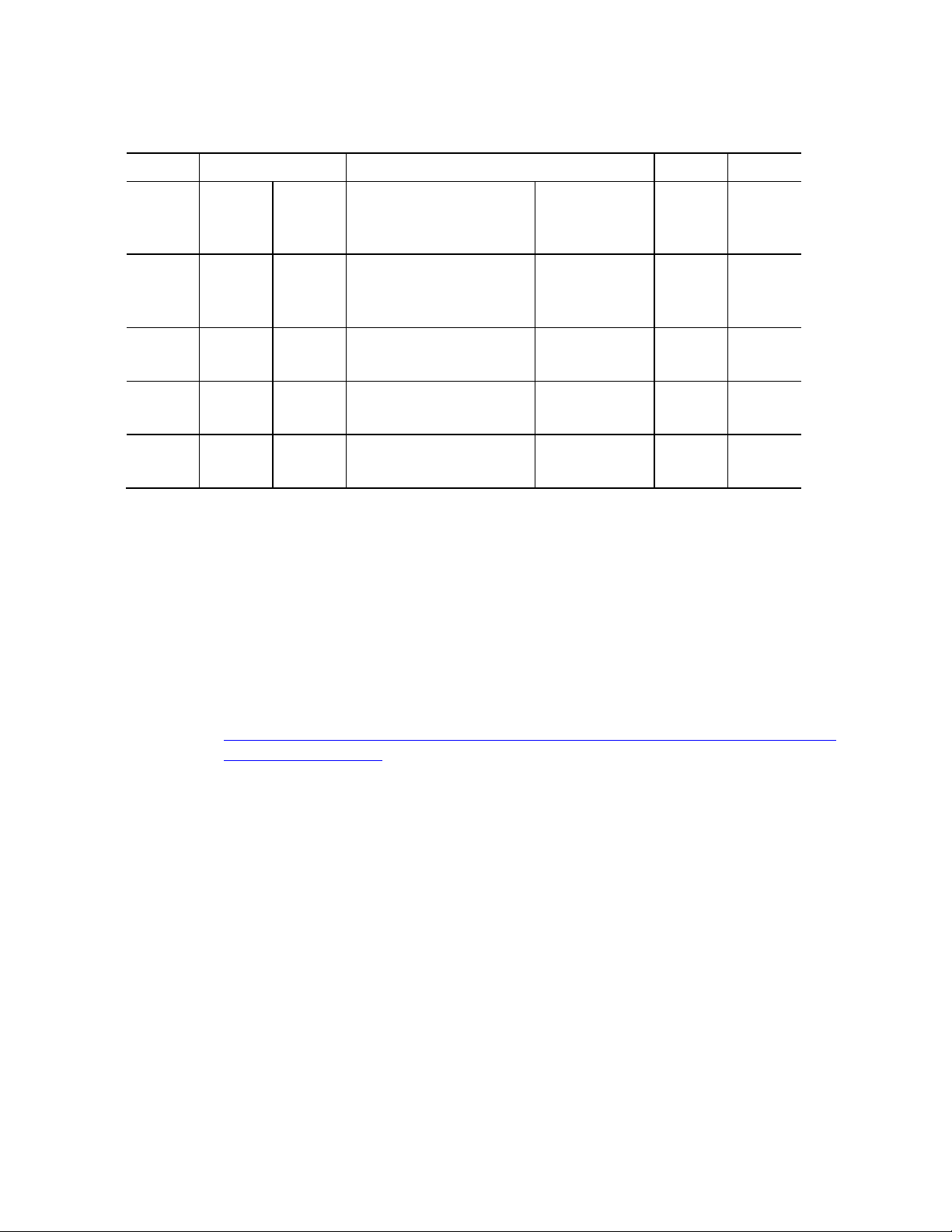
3(1)(k): The operating condition class is A2.
Dry bulb temp °C
Humidity range, non-condensing
Operati
ng
conditi
Allowab
le
range
Reco
m
mend
Allowable range
Recommended
range
Max
dew
point (°
C)
Maximu
m rate
of
change
A1
15- 32
18-27
–
12 °C Dew Point (DP)
and
8 % relative
humidity (RH) to
17 °C DP and 80 % RH
–
9 °C DP to
15 °C DP
and
60 %
17
5/20
A2
10-35
18-27
–
12 °C DP and 8 % RH
to
21 °C DP and 80 %
Same as A1
21
5/20
A3
5-40
18-27
–
12 °C DP and 8 % RH
to
24 °C DP and 85 %
Same as A1
24
5/20
A4
5-45
18-27
–
12 °C DP and 8 % RH
to
24 °C DP and 90 %
Same as A1
24
5/20
3(1)(l): The idle state power at the higher boundary temperature of the operating conditions
class is 354.5 W.
3(1)(m): The active state efficiency and performance is 44.7.
3(1)(n): There are two methods by which a user can securely delete data from this system. The
user performing secure data deletion should be an IT professional.
The first is with a Unified Extensible Firmware Interface (UEFI) shell utility. This utility
works on X10/X11/X12/H11/H12/M11 motherboard series with onboard SATA/NVMe
devices. Any user may access and download this utility through following link:
https://www.supermicro.com/about/policies/disclaimer.cfm?url=/wftp/utility/Lot9_Secure
_Data_Deletion_Utility/
Download the shell utility package and extract it to a USB flash drive, then plug the drive
into the server for which secure data deletion is necessary. Then turn the system on.
Navigate to the BIOS setup menu, then place the server system into the UEFI shell
environment. Follow the instructions in the README file to invoke the utility and
complete the deletion.
The second method is through the secure data deletion tool provided by the original
manufacturer of the hard drive. This should be used in a scenario where the shell utility
is not applicable. Each manufacturer should have the tool available on their website. If
needed, please look on the hard drive label for the name of the manufacturer and model
information.
3(1)(o): List of recommended combinations of blade servers with chassis: N/A.
3(1)(p): List of all current SKUs within this product family: SYS-220U-MTNR.
3(3)(a): There is no use of cobalt in batteries in this product.

The indicative weight range of neodymium in the HDD is 0.0 if manufactured by Western
Digital, and is between 5-25 grams if manufactured by Seagate.
3(3)(b): Please see the disassembly instructions on the next page.

Illustrated System Disassembly Instructions
Please note:
All the illustrations in the below disassembly instructions are for demonstration only.
Components shown here may not match exactly with the components in your system.
CAUTION: Always power off the system and unplug the power cord(s) first
before disassembling the system!
1. Chassis Cover
Type and number of fastenings:
Two (2) Phillips screws, one (1) locking latch.
Tools required:
Screwdriver with PH2 bit.
Procedure:
1. Remove the screws on each side of the cover.
2. Lift the locking latch, then slide the cover toward the rear and lift off.

2. Data Storage Devices
Type and number of fastenings:
One (1) latch, and two (2) locking clasps.
Tools required:
None.
Procedure:
1. Push the release button on the drive carrier to extend the drive carrier handle.
2. Use the drive carrier handle to pull the drive out of the chassis.
3. Pull out the two blue locking clasps on the left outer side of the carrier and lift the drive out.

3. Memory
Type and number of fastenings:
Two (2) latches per memory module.
Tools required:
None.
Procedure:
Press both release tabs on the ends of the memory module to unlock it. Once the
module is loosened, remove it from the memory slot.

4. Processor
Type and number of fastenings:
Four (4) T30 Torx screws.
Tools required:
Screwdriver with T30 Torx bit and slotted bit.
Procedure:
1. Use a T30-bit screwdriver to loosen the four peek nuts on the heatsink in the sequence of A,
B, C, and D.
2. Press the four rotating wires inward to unlatch the processor heatsink module as shown
below.
3. Gently lift the processor heatsink module up to remove it from the processor socket.

4. Unlock the lever and push it upward to disengage the processor from the carrier as shown in
the picture. Carefully remove the processor from the carrier. Handle the processor with care
to avoid damage.

5. Fans
Type and number of fastenings:
Four (4) Phillips screws per fan.
Tools required:
Phillips screwdriver with PH2 bit.
Procedure:
Using the handle, pull the drawer with the fan from the chassis. Remove the Phillips
screws to remove the fan from the fan drawer.

6. Power Supplies
Type and number of fastenings:
One (1) latch per module.
Tools required:
None.
Procedure:
Unplug the power cord from the power supply. Push the release tab on the back of
the power supply module to the side and pull the module straight out.

7. Power Supplies
Type and number of fastenings:
For the WIO-L riser:
One (1) lever; one (1) Phillips screw for the riser/expansion card assembly;
four (4) Phillips screws for the riser attachment.
For the Ultra riser:
One (1) thumbscrew, and four (4) Phillips screws for the attachment.
Tools required:
Screwdriver with PH2 bit.
Procedure:
WIO-L Riser:
1. Flip open the lever indicated with an arrow.
2. Remove the Phillips screw that secures the assembly to the system.
3. Lift the riser/expansion card assembly from the riser card slot, pulling it up and away
from the system.
4. Remove the screws from the WIO riser card and detach the riser card from the
riser/expansion card assembly. Expansion cards must be removed before detaching riser
cards.
WIO-R Riser:
After the WIO-L riser is removed, the WIO-R riser can be removed from the riser
slot. There is no attaching hardware.
Ultra Riser Card:
Detach the assembly using the thumbscrew. Lift the Ultra riser/expansion card
assembly from the riser card slot. Remove the screws from the Ultra riser card and detach
the riser card from the assembly. Expansion cards must be removed before detaching riser
cards.

8. Expansion Card/Graphics Card
Type and number of fastenings:
One (1) Phillips screw per expansion card installed.
Tools required:
Screwdriver with PH2 bit.
Procedure:
After the riser/expansion card assembly is removed from the system, as described
above in Item #7, remove the Phillips screw from the expansion card rear I/O panel (if installed),
and pull the expansion card out of the card edge connector on the riser card.

9. Motherboard
Type and number of fastenings:
12 Phillips screws.
Tools required:
Screwdriver with PH2 bit.
Procedure:
Remove all 12 Phillips screws from the locations shown below. Lift the motherboard
from its base.

10.Batteries
Type and number of fastenings:
One (1) latch.
Tools required:
None.
Procedure:
Push aside the small clamp that covers the edge of the battery. When the battery is
released, lift it out of the holder.
11.Backplane
Type and number of fastenings:
None.
Tools required:
None.
Procedure:
1. Disconnect all cables.
2. Release the backplane from the chassis by pulling on the spring latch on the backplane to
disengage it from the chassis.
3. Slide the backplane horizontally to allow the six backplane holes to slide off from the chassis
pegs. Remove the backplane from the chassis.

Table of contents
Popular Power Supply manuals by other brands

Matsusada Precision
Matsusada Precision R4G Series instruction manual

Proportion-Air
Proportion-Air PS-400 quick start guide

FEAS
FEAS LDR30MH24 operating instructions

Bluetti
Bluetti EP500 user manual

Phoenix Contact
Phoenix Contact UNO POWER UNO-PS/1AC/24DC/30W Installation notes

Ametek
Ametek Sorensen XT Series Operation manual