manuals.online logo
Brands
  1. Home
  2. •
  3. Brands
  4. •
  5. Supermicro
  6. •
  7. Switch
  8. •
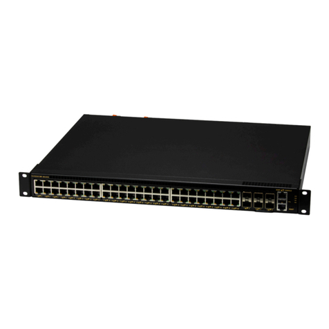
  9. Supermicro SSE-F3548SR User manual

Supermicro SSE-F3548SR User manual

This manual suits for next models

1

Other Supermicro Switch manuals

Supermicro SSE-G24-TG4 User manual

Supermicro

Supermicro SSE-G24-TG4 User manual

Supermicro MicroBlade MBM-GEM-004 User manual

Supermicro

Supermicro MicroBlade MBM-GEM-004 User manual

Supermicro SuperBlade SBM-GEM-X2C User manual

Supermicro

Supermicro SuperBlade SBM-GEM-X2C User manual

Supermicro SSE-C3632S User manual

Supermicro

Supermicro SSE-C3632S User manual

Supermicro SSE-G3748 Series User manual

Supermicro

Supermicro SSE-G3748 Series User manual

Supermicro L2 User manual

Supermicro

Supermicro L2 User manual

Supermicro SSH-C48Q User manual

Supermicro

Supermicro SSH-C48Q User manual

Supermicro SSE-G2252 User manual

Supermicro

Supermicro SSE-G2252 User manual

Supermicro Intelligent Switch User manual

Supermicro

Supermicro Intelligent Switch User manual

Supermicro L2 User manual

Supermicro

Supermicro L2 User manual

Supermicro L2 User manual

Supermicro

Supermicro L2 User manual

Supermicro SSE-X3648S User manual

Supermicro

Supermicro SSE-X3648S User manual

Supermicro SSH-C48Q User manual

Supermicro

Supermicro SSH-C48Q User manual

Supermicro SSE-G24-TG4 User manual

Supermicro

Supermicro SSE-G24-TG4 User manual

Supermicro SuperBlade Series User manual

Supermicro

Supermicro SuperBlade Series User manual

Supermicro SSE-G3648B User manual

Supermicro

Supermicro SSE-G3648B User manual

Supermicro SSE-X3348T User manual

Supermicro

Supermicro SSE-X3348T User manual

Supermicro SSE-X3348S User manual

Supermicro

Supermicro SSE-X3348S User manual

Supermicro L2 User manual

Supermicro

Supermicro L2 User manual

Supermicro SSE-G24-TG4 User manual

Supermicro

Supermicro SSE-G24-TG4 User manual

Supermicro SSH-C48Q User manual

Supermicro

Supermicro SSH-C48Q User manual

Supermicro SSE-G24-TG4 User manual

Supermicro

Supermicro SSE-G24-TG4 User manual

Supermicro SSE-G24-TG4 User manual

Supermicro

Supermicro SSE-G24-TG4 User manual

Supermicro SSE-G48-TG4 User manual

Supermicro

Supermicro SSE-G48-TG4 User manual

Popular Switch manuals by other brands

SMC Networks SMC6224M Technical specifications

SMC Networks

SMC Networks SMC6224M Technical specifications

Aeotec ZWA003-S operating manual

Aeotec

Aeotec ZWA003-S operating manual

TRENDnet TK-209i Quick installation guide

TRENDnet

TRENDnet TK-209i Quick installation guide

Planet FGSW-2022VHP user manual

Planet

Planet FGSW-2022VHP user manual

Avocent AutoView 2000  AV2000BC AV2000BC Installer/user guide

Avocent

Avocent AutoView 2000 AV2000BC AV2000BC Installer/user guide

Moxa Technologies PT-7728 Series user manual

Moxa Technologies

Moxa Technologies PT-7728 Series user manual

Intos Electronic inLine 35392I operating instructions

Intos Electronic

Intos Electronic inLine 35392I operating instructions

Cisco Catalyst 3560-X-24T Technical specifications

Cisco

Cisco Catalyst 3560-X-24T Technical specifications

Asante IntraCore IC3648 Specifications

Asante

Asante IntraCore IC3648 Specifications

Siemens SIRIUS 3SE7310-1AE Series Original operating instructions

Siemens

Siemens SIRIUS 3SE7310-1AE Series Original operating instructions

Edge-Core DCS520 quick start guide

Edge-Core

Edge-Core DCS520 quick start guide

RGBLE S00203 user manual

RGBLE

RGBLE S00203 user manual

Thrustmaster FLIGHT SIMULATOR X quick guide

Thrustmaster

Thrustmaster FLIGHT SIMULATOR X quick guide

Southwire SURGE GUARD 41390 RVC troubleshooting guide

Southwire

Southwire SURGE GUARD 41390 RVC troubleshooting guide

Buhler Nivotemp NT 61 Brief instructions

Buhler

Buhler Nivotemp NT 61 Brief instructions

Kramer VS-41HDCP user manual

Kramer

Kramer VS-41HDCP user manual

Techly IDATA AU-270 user manual

Techly

Techly IDATA AU-270 user manual

Belkin F1U109 user manual

Belkin

Belkin F1U109 user manual

manuals.online logo
manuals.online logoBrands
  • About & Mission
  • Contact us
  • Privacy Policy
  • Terms and Conditions

Copyright 2025 Manuals.Online. All Rights Reserved.

Quick Installation Guide
SSE-F3548S SSE-F3548SR
48 × 25GbE + 6 × 100GbE DC switch
Power Cords × 2
Rack-mounting kit (M3 flat head screws x 4; M4 pan head
screws x 2; M4 flat head screws x 2; M5 screws x 6; Cage
nuts x 6; Ear brackets x2; Rear brackets x2; Front
brackets(long) x 2; Front bracket(short) x 2)
RJ-45 to DB-9 serial console cable
Quick Installation Guide
Detailed installation instructions are contained in a User Manual
available on the Supermicro website at:
https://www.supermicro.com/products/accessories/Networking/SS
E-F3548S.cfm
Instructions for rack mounting using ear brackets are included in the
manual and summarized below.
The switch can be mounted in a standard 19-inch equipment rack or
on a horizontal surface.
The switch can be mounted in a rack using the supplied rack-
mounting kit.
The installation instructions are shown below:
Step 1. Install the ear brackets
A. Secure the ear brackets to the switch with the M3 flat head screws.
Step 2. Install the front brackets
A. Secure the front brackets to the switch with the M4 flat head
screws.
P.S. There are two types of front-brackets. Front-bracket-long can
support a rack between 850mm and 1000mm deep, and Front-bracket-
short can support a rack between 700mm and 850mm deep.
Step 3. Install the switch into a rack
A. Secure the switch to a rack with the M5 screws and cage nuts.
Step 4 Install the rear brackets
A. Secure the rear brackets to the rack with M5 screws and cage nuts.
Step 5 Secure the rear brackets
A. Secure the rear brackets to the front brackets with the M4 pan
head screws.
SELECTING A SITE
MOUNTING
Ear bracket
M3 screw
Front-bracket
M4 screw
○
1
○
2
○
3
M5 screw
Rear-bracket
Cage nut
M4 screw
M5 screw
Cage nut
PACKAGE CONTENTS
Quick Installation Guide
SSE-F3548S SSE-F3548SR
Connect the required devices with the appropriate cables.
To connect a device to a power source:
1. Insert the Power Supply Unit (PSU) cable plug directly into the AC
socket of a PSU located at the back of the switch.
Note: For electrical safety purposes, please pay attention to the
following warning notices printed on the switch:
Caution: Disconnect the power cord from all power sources to
completely remove power from the device.
Caution: If the installation requires a different power cord than the one
supplied with the device, make sure you use a power cord displaying
the mark of the safety agency that defines the regulations for power
cords in your country. The mark is your assurance that the power cord
can be used safety with the device.
2. Plug the other end of the cable into a grounded, 3-pin, AC power
source.
Note: For use outside North America, you may need to change the AC
line cord. You must use a line cord that has been approved for the
connector type in your country.
3. Repeat steps 1 and 2 for the second PSU module. Two installed PSU
modules operate in a load-sharing mode and provide 1+1
redundancy.
To set up your management connection, the following parameters
should be observed:
Console Interface—make sure your console settings are 115200-
N-8-1 (baud rate 115, 200 bps).
Network Interface:
Ports 1–48: 25 Gbps SFP28 transceiver slots
Ports 49–54: 100 Gbps QSFP28 transceiver slots
Transceivers: SFP28/QSFP28-SR, SFP28/QSFP28-LR
Direct Attach Cables can also be used in ports 1–54.
Weight: Net weight: 8.9 kg with 2 PSUs
LEDs:
ID
System
Fan
SFP28 Ports 1–48: Status (Link/Activity)
QSFP28 Ports 49–54: Status (Link/Activity)
Size: W 445 ×D 510 ×H 44 mm
Temperature: Operating 0 °C to 45 °C
AC Input: 100–240 V〜, 50 Hz–60 Hz, 4.25 A max per PS
DC Output: +12 V 44 A, +12 Vsb 2.1 A
Power Supply:
100–240 V〜, 8-4A, 50 Hz–60 Hz, F2B 550 W @ +12 V 44A, +12
Vsb 2.1A per PS
Power Consumption: 410 watts
FCC part 15 Class A, ICES-003 Class A
EN 55032:2015 + AC: 2016, Class A
CISPR 32:2015 + COR1:2016, Class A
AS/NZS CISPR32:2015, Class A
EN 61000-3-2:2014, Class A
EN 61000-3-3:2013
EN 55024:2010+A1:2015
EN 61000-4-2:2009 / IEC 61000-4-2:2008 ED. 2.0
EN 61000-4-3:2006 +A1:2008 +A2:2010 / IEC 61000-4-3:2010 ED. 3.2
EN 61000-4-4:2012 / IEC 61000-4-4:2012 ED. 3.0
EN 61000-4-5:2014 / IEC 61000-4-5:2014 ED. 3.0
EN 61000-4-6:2014/ IEC 61000-4-6:2013 ED. 4.0
EN 61000-4-8:2010 / IEC 61000-4-8:2009 ED. 2.0
EN 61000-4-11:2004 / IEC 61000-4-11:2004 ED. 2.0
Safety: IEC/EN/CSA 60950-1
Caution:
Installation and removal of the unit must be carried out by
qualified personnel only.
The unit must be connected to a grounded outlet to comply with
international safety standards.
Do not connect the unit to an A.C. outlet (power supply) without
a ground connection.
The appliance coupler (the connector to the unit and not the wall
plug) must have a configuration for mating with an IEC/EN 60320-
1 appliance inlet.
The socket outlet must be near to the unit and easily accessible.
You can only remove power from the unit by disconnecting the
power cord from the outlet.
Caution:

Fiber Optic Port Safety. When using a fiber optic
port, never look at the transmit laser while it is
powered on. Also, never look directly at the fiber
TX port and fiber cable ends when they are
powered on.
This product does not contain any serviceable user parts.
Installation and removal of the unit must be carried out by
qualified personnel only.
When connecting this device to a power outlet, connect the field
ground lead on the tri-pole power plug to a valid earth ground line
to prevent electrical hazards.
This switch uses lasers to transmit signals over fiber optic cable.
The lasers are compliant with the requirements of a Class 1 Laser
Product and are inherently eye safe in normal operation. However,
you should never look directly at a transmit port when it is
powered on.
Wear an anti-static wrist strap or take other suitable measures to
prevent electrostatic discharge when handling this equipment.
Do not plug a phone jack connector in the SFP28 port. This may
damage this device.
Use only twin-axial cables with SFP28 connectors that conform to
FCC standards.
This product may cause interference if used in residential areas.
Such use must be avoided unless the user takes special measures
to reduce electromagnetic emissions to prevent interference to the
reception of radio and television broadcasts.
For more information and safety instruction, visit:
http://www.supermicro.com/about/policies/safety_information.cfm
ETHERNET CABLING
CONNECTING THE POWER CABLE
QUICK START-UP
PHYSICAL CHARACTERISTICS
COMPLIANCES
POWER CORD
CAUTIONARY MESSAGES