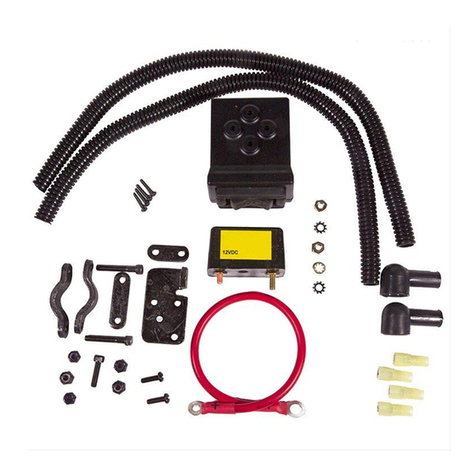
Installation Procedure:
Step 1: Reel off about 2' of wire rope from your winch by powering out or by using the freewheel feature.
Step 2: Mount the switch plate to the surface from which you wish to control the winch. Using the switch plate for a template, drill (2)
holes for the screws with a 9/64 drill or a No. 29 Drill. Attach the switch plate with the screws provided.
Step 3: Remove the switch handle and assemble the switch to the switch plate as shown. Reattach the handle.
Step 4: Run 8 gauge wires from the switch A1 and A2 terminals to the winch motor as shown in illustration.
Step 5: Run one 8 gauge wire from the B1 switch terminal to the battery. DO NOT make the connection to the battery at this time.
Step 6: Run one 8 gauge wire from the B2 switch terminal to the negative battery terminal, or to a suitable ground such as a bolt attach-
ing a part to the chassis. Scrape off any paint or dirt from the bolt or chassis that would prevent a good electrical connection.
The switch terminals (A1 and A2) are shorted when the switch is in the OFF position. Make sure the ”A“ termi-
nals are connected to the winch motor and the ”B“ terminals are connected to the battery.
Step 8: Connect the wire from the B1 terminal to the circuit breaker that came with your winch. Connect the circuit breaker to the posi-
tive terminal of the battery.
Step 9: Test your winch for proper rotation by turning the switch briefly to the ”Cable Out“ position. You may need an assistant to watch
the winch during this test. If the winch rotates in the wrong direction, reverse the wires attached to the motor.


