Supmeter BST106-M60S(L) User manual

BST106-M60S[L] Guide Rail Type
Weighing / Force Measuring Control Module
Weight/Force Display, Peak Value Detection / Display Holding,
Auto Weight-checking, Setpoint DO Output, AO/Digit Transmission
Operation Manual V3.0
Changsha Supmeter Technological Co.,Ltd.

1
Preface
Thank you very much for your purchase!
This manual covers safety precaution, technical specifications, user interfaces, installation&
connection, functions&operation and so on. In order to make the product running at its best, please read
this manual in advance, and reserve it for the future reading.
The technology update, function enhancement and quality improvement may lead to some differences
between this manual and the physical product, please understand.
Without our authorization, the contents of this manual are not allowed to be copied and reproduced.
Main Features:
Applications: Weight/Force Display, Peak Value Detection&Display Holding, Auto
Weight-checking, Setpoint DO Output and AO/Digit Transmission.
EMC design with high anti-jamming capability, suitable for industrial environment.
32-bit ARM CPU with 48MHz clock & high arithmetic speed.
6+6 Red LED digital tubes for English character and digit display.
4-key English keypad for Menu&Shortcut mode operation.
24-bit High-precision and high-speed ∑-△A/D conversion module with 1/1,000,000 internal
resolution and max. sampling frequency 3200Hz.
Special anti-vibration digital filtering algorithm for ensuring the weighing stability and accuracy
when there is strong vibration on the load receptor, and the rapid response capability when the
weight signal changes.
Max. Connection Quantity: 8 Loadcells (350Ω).
Zero Upon Power Up, Zero Auto-tracking, Manual/Auto Zero and Zero Calibration available.
Load Calibration, Data Calibration, Segmenting Span Correction and Segmenting Weight
Calculation available.
Auto-locking, Key-locking, Key-unlocking, Digital Setting&Calibration and I/O Testing
functions available.
3 Definable normally open switch inputs [DI] and 3 definable normally open transistor switch
outputs [DO].
1 Optional&definable current signal output [AO: 0~20mA].
1 Optional&definable voltage signal output [VO: 0~10V].
RS232, optional RS485 and CANBUS communication ports for connecting Host IPC/PLC and
LED Remote Display.
With the multitasking mode, the weighing/force measuring process, alarm output and signal
transmission will not be interrupted by parameter setting and the other operations.

2
Contents
1. SAFETYPRECAUTION.................................................................................................................3
2. TECHNICAL SPECIFICATIONS..................................................................................................4
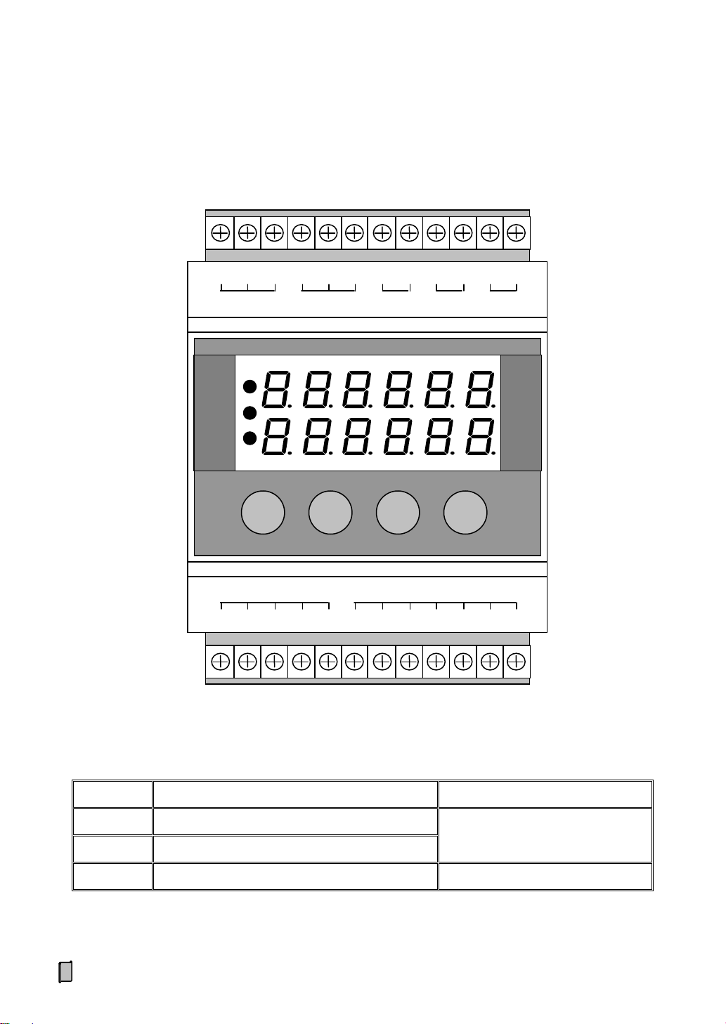
3. USER INTERFACE..........................................................................................................................6
3.1 USER INTERFACE DIAGRAM .................................................................................................................. 6
3.2 STATE INDICATION................................................................................................................................. 6
3.3 KEYPAD OPERATION.............................................................................................................................. 7
3.4ALARM SIGNS ....................................................................................................................................... 7
4. INSTALLATION&CONNECTION................................................................................................8
4.1 INSTALLATION....................................................................................................................................... 8
4.2 TERMINAL............................................................................................................................................. 9
5. OPERATION PROCEDURE ........................................................................................................11
6. FUNCTIONS&OPERATION........................................................................................................12
6.1 MAIN DISPLAY INTERFACES................................................................................................................ 12
6.1.1 Real-time Weight Value and Percent [L] ................................................................................... 12
6.1.2 Real-time Weight, Peak Hold Value or Checking-weight Value [P].......................................... 12
6.1.3 Real-time Weight, AO Output Value [Ao]................................................................................. 12
6.1.4 Real-time Weight, VO Output Value [Vo] ................................................................................. 13
6.1.5 Real-time Weight, Communication State [Co].......................................................................... 13
6.2 MAIN MENU........................................................................................................................................ 14
6.3 F1-SET PARAMETER SETTING............................................................................................................. 16
6.3.1 Weighing Parameters (SCAL) ................................................................................................... 16
6.3.2 Calibration Parameters (CALP)................................................................................................. 18
6.3.3 Setpoint Parameters (SEtP) ....................................................................................................... 20
6.3.4 Communication Parameters (SErP)........................................................................................... 23
6.3.5 Display Parameters (dISP) ........................................................................................................ 24
6.3.6 A Sample of Parameter Setting.................................................................................................. 25
6.4 F2-CALSYSTEM CALIBRATION .......................................................................................................... 26
6.4.1 Zero Calibration (ZEro)............................................................................................................. 26
6.4.2 Data Calibration (dAtA)............................................................................................................ 27
6.4.3 Load Calibration (LoAd)........................................................................................................... 29
6.4.4 Segmenting Span Correction (SEgC)........................................................................................ 30
6.5 F5-LOC KEY-LOCKER......................................................................................................................... 31
6.5.1 Key-unlocking (oPEn)............................................................................................................... 31
6.5.2 Key-locking (Locc) ................................................................................................................... 31
6.5.3 Password Set (PASS)................................................................................................................. 32
APPENDIXA. REGISTER TABLE OF HOST-SLAVE MODBUS[ASCII/RTU]........................33
APPENDIX B. DATA FRAME FORMAT OFCONTINUOUS SENDING [ASCII]....................36

3
1. Safety Precaution
Application environment
Make sure that this product works under the environment where is accord with the technical
specifications.
Do not open the shell before power-off.
Cable Laying
Weighing signal, analog signal and communication signal cables should be laid in pipes, and
do not lay them together with power cables.
Power Supply
The power supply of the controller should be separated from the power supply of the driving
devices.
Please make sure that the inputted voltage is correct before power-on.
Environmental Protection
While being discarded as worthless, the product should be processed lawfully as leady
industrial waste for environment protection.
Other Notes
The installation, wiring and maintenance should be operated by the engineers with the
relevant professional knowledge and safety operation ability.
Although being not described in this manual, the relevant safety operating procedures and
standards should be followed.

4
2. Technical Specifications
Executing Standards
PRC GB/T 7724-2008《National Standard for Electronic Weighing Meter》.
PRC JJG 649-2016《National Verification Regulation for Digital Weighing Indicators (Weighing
Indicators)》.
OMIL R76-1: 2006《Non-automatic Weighing Instruments》International Recommendation.
Accuracy Grade:○
Ⅲ.
Number of Verification Scale Interval: n=3000.
Display
6+6 Red LED digital tubes for English character and digit display.
Weight Display Range: -9,999~+99,999.
Scale Capacity: Setting Range 1~99,999.
Scale Division: Optional 1, 2, 5, 10, 20, 50, 100, 200, 500.
Display Resolution: 1/50,000.
Decimal Point Position: Optional 0, 0.0, 0.00, 0.000, 0.0000.
Display Refreshing Time: Setting Range 0.01~1.00s.
Keypad
4-key English keypad for Menu&Shortcut mode operation.
Weighing Signal Interface
Excitation Voltage/Max. Current: DC5V/120mA [8-350Ω loadcells].
Signal Input Range: 0~12.5mV.
Output Sensitivity of Loadcell: 1.0~2.5mV/V.
24-bit ∑-△ADC with internal resolution 1/1,000,000.
Optional Sampling Frequency: 3200Hz, 1600Hz, 800Hz, 400Hz, 200Hz, 5Hz.
Special Anti-vibration Digital Filtering Algorithm for precise weighing, stable display and rapid
response.
Zero Drift: ±0.1μV/℃RTI (Relative to Input).
Gain Drift: ±5ppm/℃.
Non-linearity: 0.005%FS.
Switch&Analog Signal Interface
3 Optional&definable normally open switch inputs [DI].
3 Optional&definable normally open transistor switch outputs [DO]: DC24V, 250mA..
1 Optional&definable current signal output [AO: 0~20mA], Non-linearity: 0.05%FS.
1 Optional&definable voltage signal output [VO: 0~10V], Non-linearity: 0.05%FS.
Digital Communication Interface
COM1: RS232.
COM2: Optional RS485.

5
COM3: Optional CANBUS.
Connectable: Host IPC/PLC and LED Remote Display.
Operating Specification
Operating Voltage: DC12~24V.
Max. Power Consumption: 3W.
Outline Size: 71.5×113×57.9mm [W×H×D].
Guide rail type installation.
Guide Rail Groove Size: 35×1.6 mm [W×H×D].
Operating Temperature: -25℃to +45℃.
Storage Temperature: -30℃to +60℃.
Relative Humidity: Max. 85%RH.
Weight: Approx. 167g.

6
3. User Interface
3.1 User Interface Diagram
3.2 State Indication
LED light
Description
Note
[AH]
Upper Limit Alarm.
Refer to Parameters [200]~[203].
[AL]
Lower Limit Alarm.
[RUN]
Running State.
AH
AL
RUN
■
►
▲
S-
S+
E-
E+
SHD
DI1
DI2
DI3
DO1
DO2
DO3
COM
GND
mA+
Vo+
GND
RXD
TXD
A+
B-
H
L
DC+
DC-
LOADCELL
DI/DO
AO
RS232
RS485
CAN
POWER
1
2
3
4
5
6
7
8
9
10
11
12
12
11
10
9
8
7
6
5
4
3
2
1

7
3.3 Keypad Operation
If there is not any keypad operation in one minute and it’s not in the processes of ‘F2 System Calibration’ & ‘F6
Factory Adjustment’, the controller will return to ‘Main Display Interface’automatically.
*: Keep the key pressed for 2 seconds.
3.4 Alarm Signs
Key Name
Function
Description
【■】
【MENU】
Enter Main Menu / Exit.
【LOCK】*
Key-locking / Key-unlocking.
【►】
【►】
Cursor shifts right.
Display the previous interface or option.
【ZERO】*
Manual Zero without Power-down Protection.
【▲】
【▲】
Display the next interface or option.
Digit input: +1 ( 0~9 loop).
【SET】*
Setpoint Parameters Setting.
【】
【ENT】
Enter / Save / Clear Alarm.
【CLS】*
Clear Screen [Clear the display value of Peak Hold Value and
Weight-checking Value].
Sign
Alarm Cause
Solution
Err1
RAM Failure.
Replace the chip RAM.
Err2.1
Err2.2
EEPROM Failure.
Replace the chip EEPROM.
Err3
Unused.
Err4
ADC Failure.
Replace the ADC module.
oV-Ad
Over ADC Range.
Weighing signal exceeds A/D conversion range.
1. Check if the loadcell is connected.
2. Check if the capacity of loadcell is too small.
3. Check if the loading weight is too big.
oL
Overload Alarm.
Gross Weight > (Scale Capacity + 9 ×Scale Division).
1. Check if the loadcell is connected.
2. Check if the capacity of loadcell is too small.
3. Check if the loading weight is too big.
oV-nZ
Over ‘Manual/Auto Zero Limit’.
Refer to parameter [123] ‘Manual/Auto Zero Limit’.
tXX.XX
Preheating Time Countdown
[min.sec].
Refer to parameter [128] ‘Zero Upon Power Up’, [129]
‘Power Up Zero Time’and [130] ‘Power Up Zero Limit’.
Wait for the preheating time over or press any key to exit.
oV-Zr
Over ‘Power Up Zero Limit’.

8
4. Installation&Connection
4.1 Installation
Outline Size
W×H×D[mm]
Guide Rail Groove Size
W×D[mm]
71.5×113×57.9
35×1.6
71.5
57.9
113
35
1.6
Plastic Fastener

9
4.2 Terminal
No.
Pin
Description
LOADCELL
Loadcell Port
1
S-
Weighing Signal Input +.
2
S+
Weighing Signal Input -.
3
E-
Excitation Voltage -.
4
E+
Excitation Voltage + [DC5V].
5
SHD
Shield Ground.
DI/DO
Switch Input/Output Port [Definable]
6
DI1
Switch Signal Input 1.
7
DI2
Switch Signal Input 2.
8
DI3
Switch Signal Input 3.
9
DO1
Normally Open Contact Output 1.
10
DO2
Normally Open Contact Output 2.
11
DO3
Normally Open Contact Output 3.
12
COM
DI/DO Common Terminal.
Contact Capacity of Transistor Switch: DC24V, 250mA.
S-
S+
E-
E+
SHD
DI1
DI2
DI3
DO1
DO2
DO3
COM
LOADCELL
DI/DO
1
2
3
4
5
6
7
8
9
10
11
12

10
No.
Pin
Description
POWER
DC12~24V Power Input Port
1
DC-
DC Input -.
2
DC+
DC Input +.
CAN [Optional]
CANBUS Digital Communication Port [COM3]
3
L
Data -.
4
H
Data +.
RS485
RS485 Digital Communication Port [COM2]
5
B-
Data -.
6
A+
Data +.
RS232
RS232 Digital Communication Port [COM1]
7
TXD
Transmit Data.
8
RXD
Receive Data.
9
GND
Signal Ground.
AO
Analog Output Port [Definable]
10
Vo+
0~10V Voltage Signal Output] +.
11
mA+
0~20mA Current Signal Output +.
12
GND
VO/AO Output -.
GND
mA+
Vo+
GND
RXD
TXD
A+
B-
H
L
DC+
DC-
AO
RS232
RS485
CAN
POWER
12
11
10
9
8
7
6
5
4
3
2
1

11
5. Operation Procedure
Connection & Power on
Zero Calibration
Other Settings
Key-locking
Scale Setting
Zero Auto-tracking Limit &
Manual/Auto Zero Limit Setting
Setpoint Setting
[Data Calibration]
Load Calibration
[Segmenting Correction]

12
6. Functions&Operation
6.1 Main Display Interfaces
【►】【▲】: Display interface switch.
6.1.1 Real-time Weight Value and Percent [L]
6.1.2 Real-time Weight, Peak Hold Value or Checking-weight Value [P]
6.1.3 Real-time Weight, AO Output Value [Ao]
Weight Percent L% = (Weight / Scale Capacity)×100%.
AH
AL
RUN
AO: 0.00~20.00mA.
AH
AL
RUN
AH
AL
RUN
[203]=0: P=0.
[203]=1: P=Weight Peak Value.
[203]=2: P=Checking-weight Value.
Refer to parameter [203] ‘Data Compared with Weight Setpoints’.

13
6.1.4 Real-time Weight, VO Output Value [Vo]
6.1.5 Real-time Weight, Communication State [Co]
VO: 0.00~10.00V.
AH
AL
RUN
gd: Normal; no: No Communication; Er: Error.
AH
AL
RUN

14
6.2 Main Menu
Main Menu
Second Menu
Sign
Function
Sign
Description
F1.SEt
Parameter
Setting
-SCAL
Scale parameters setting.
-CALP-
Calibration parameters setting.
-SEtP-
Setpoint parameters setting.
-SErP-
Communication parameters setting.
-dISP-
User interface parameters setting.
F2.CAL
System
Calibration
-ZEro-
Zero Calibration without loading on the weigher to correct Zero
Value.
-dAtA-
Data Calibration: Input the specification parameter values of
loadcell according to the actual configuration of the weighing
system to correct Span Coefficient. If there is no access to get the
specification parameter values for Data Calibration, then it’s
necessary to do Load Calibration.
-LoAd-
Load Calibration: After doing Data Calibration, if there are
conditions for Load Calibration, do Load Calibration with loading
standard weight on the weigher to correct Span Coefficient further
for higher weighing accuracy.
-SEgC-
Segmenting Span Correction: After doing Zero Calibration and
Load Calibration [or Data Calibration], it’s allowed to do
Segmenting Span Correction with loading standard weight on the
weigher by 10 Correction Points to get Span Correction Ratio of 10
linearity segments for higher weighing accuracy.
F3.rEC
Unused.
F4.CLn
Clear Screen: Clear the display value of Peak Hold Value and
Weight-checking Value.
F5.Loc
Key-locker
-oPEn-
Key-unlocking.
-Locc-
Key-locking.
-PASS-
Password Set.
Exfactory Passwords:
Operator Password: 000.
Administrator Password: 001.

15
Main Menu
Second Menu
F6.FAC
Factory
Adjustment
Special for manufacturer.
-SPAn-
【mV】Exfactory Span Adjustment: Use standard weighing test
equipment to adjust the weighing signal interface for normalizing
Span Coefficient to 1.
-AdtS-
Weighing Signal Linearity Test.
-AVZF-
AO [0~20mA] Zero/Full Adjustment.
VO [0~10V] Zero/Full Adjustment.
-AVtS-
AO [0~20mA] Linearity Test.
VO [0~10V] Linearity Test.
-dIdo-
DI/DO Input&Output Test.
-dEFU-
RAM Reset: Reset to factory defaults.
-dStS-
Display/DO Reliability Test.
F7.InF
Product
Information
Only for query.
--VEr-
Version No.
--Sn--
Serial No.
-dAtE-
Exfactory Date.
-HArd-
Hardware Configuration.

16
6.3 F1-SET Parameter Setting
6.3.1 Weighing Parameters (SCAL)
No.
Sign
Range
Default
Description
Set
100
Ut
0~3
1
Weight Unit
0: None
1: kg
2: t
3: g
101
dt
0~4
ooo.oo
Decimal Point Position
0: ooooo
1: oooo.o
2: ooo.oo
3: oo.ooo
4: o.oooo
102
SL
1~99999
10000
Scale Capacity
Max. allowed loading weight of the load receptor.
Scale Capacity≤(Loadcell Capacity × Loadcell
Quantity) –Self-weight of Load Receptor.
103
dV
1~500
1
Scale Division
1, 2, 5, 10, 20, 50, 100, 200, 500
104
ZE
-99999~
+99999
0
[*]
Zero Value
Only for query.
105
SP
>0
1.0000
[*]
Span Coefficient
Max. display value: 9.9999.
Only for query.
106
Sr
0~5
0
Stability Range [Division]
Set value = 0: No ‘Stability Judging’.
Set value > 0: Weight Variance per [107] ‘Stability
Time’being in [106] ‘Stability Range’means
‘Weight is stable’.
107
St
0.1~9.9
0.5
Stability Time [s]
[*]: ‘RAM Reset’operation has no effect on the parameter.

17
No.
Sign
Range
Default
Description
Set
108
Fc
0~5
0
Sampling Frequency [Hz]
0: 5 Hz
1: 200 Hz
2: 400 Hz
3: 800 Hz
4: 1600Hz
5: 3200Hz
109
Ft
0~9
5
Anti-vibration Digital Filter1
Set Value
Cutoff Frequency
0
None
1
11.2Hz
2
8.0Hz
3
5.6Hz
4
4.0Hz
5
2.8Hz
6
2.0Hz
7
1.4Hz
8
1.0Hz
9
0.7Hz
110
Sb
1~128
1
Weight Display Smooth Filter2
The bigger set value of Filter2 will make the weight
display value more stable with slower response
speed.
111
EL
0.01~
9999.99
1
Weight Display Multiplier
It’s for enlarging or lessening the weight dispay
value.
[*]: ‘RAM Reset’operation has no effect on the parameter.

18
6.3.2 Calibration Parameters (CALP)
No.
Sign
Range
Default
Description
Set
120
ZP
0~1
0
Zero Auto-tracking Permission
0: oFF
1: on [Only after weight being stable and the
zero variation in ‘Zero Auto-tracking Time’is
within the range of ‘Zero Auto-tracking Limit’, the
result of Zero Auto-tracking will be valid]
121
Zt
0.1~9.9
1.0
Zero Auto-tracking Time [s]
122
Zr
0.1~50.0
1.0
Zero Auto-tracking Limit [Division]
123
nZ
0~50000
50
Manual/Auto Zero Limit
Only when the weight variation caused by Zero
Value changing is within this range, Manual Zero
and Auto Zero will be valid.
Suggestion: Set value ≤(Scale Capacity ×4%).
124
dZ
0~99
5
Zero Display Limit
When the absolute value of weight is within this
range, the weight display value will return to zero.
125
tL
1~99999
12000
[*]
Total Capacity of Loadcells
Total Capacity of Loadcells = Loadcell Capacity ×
Loadcell Number. Only for query.
126
SE
0.500~5.000
2.000
[*]
Output Sensitivity of Loadcell [mV/V]
Only for query.
127
Un
0
0
Unused
128
In
0~1
0
Zero Upon Power Up
0: oFF
1: on [without Power-down Protection]
129
It
0~1800
10
Power Up Zero Time [s]
130
Ir
0~50000
50
Power Up Zero Limit
Suggestion: Set value ≤(Scale Capacity ×20%).
[*]: ‘RAM Reset’operation has no effect on the parameter.

19
No.
Sign
Range
Default
Description
Set
131
132
133
134
135
136
137
138
139
140
L1
L2
L3
L4
L5
L6
L7
L8
L9
LA[L10]
1~99999
[*]
1000
2000
3000
4000
5000
6000
7000
8000
9000
10000
Correction Point’s Loading Weight 1~10
Inputted Loading Weight value for Segmenting
Correction.
Demand: L1≤L2≤…≤L10.
Only for query.
141
142
143
144
145
146
147
148
149
150
d1
d2
d3
d4
d5
d6
d7
d8
d9
dA[d10]
-99999~
+99999
[*]
10000
20000
30000
40000
50000
60000
70000
80000
90000
99999
Correction Point’s AD Value 1~10
AD Value detected via Segmenting Correction.
Demand: d1≤d2≤…≤d10.
Only for query.
151
152
153
154
155
156
157
158
159
160
C1
C2
C3
C4
C5
C6
C7
C8
C9
CA[C10]
0.0100~
99.9999
[*]
1.0000
Span Correction Ratio 1~10
Span Correction Ratio of Linearity Segment got by
Segmenting Correction.
Linearity Segment 1:[Zero Value]~d1.
Linearity Segment 2:d1~d2.
Linearity Segment 3:d2~d3.
…
Linearity Segment 10:d9~[Max. AD Value].
Max. display value: 9.9999.
Only for query.
161
SC
0~1
0
[*]
Segmenting Weight Calculation Permission
0: oFF
1: on
Operating Authorization: Administrator.
[*]: ‘RAM Reset’operation has no effect on the parameter.
Table of contents
Other Supmeter Accessories manuals