Supmeter BST106-N59 User manual

BST106-N59[B] Shovel Loader Weigher
Operation Manual V5.0
Changsha Supmeter Technological Co.,Ltd.
www.zemicusa.info

1
Preface
Thank you very much for your purchase!
This manual covers safety precautions, brief introduction, technical specifications, operation interface,
installation&connection, function&operation, fault treatment, working specification and so on. In order to
make the product running at its best, please read this manual in advance, and reserve it for the future
reading.
The continuous technology update, performance perfection and quality improvement may lead to
some differences between this manual and the physical product, please understand.
Without our authorization, the contents of this manual are not allowed to be copied and reproduced.
Main Features:
ARM CPU system with higher arithmetic speed.
Dust-proof stainless Steel shell suitable for dust atmosphere.
EMC design with high anti-jamming capability, suitable for industrial environment.
The DC24V power input circuit of weighing indicator has reverse polarity protection function.
640×480 dots TFT color display screen for English/Chinese character display.
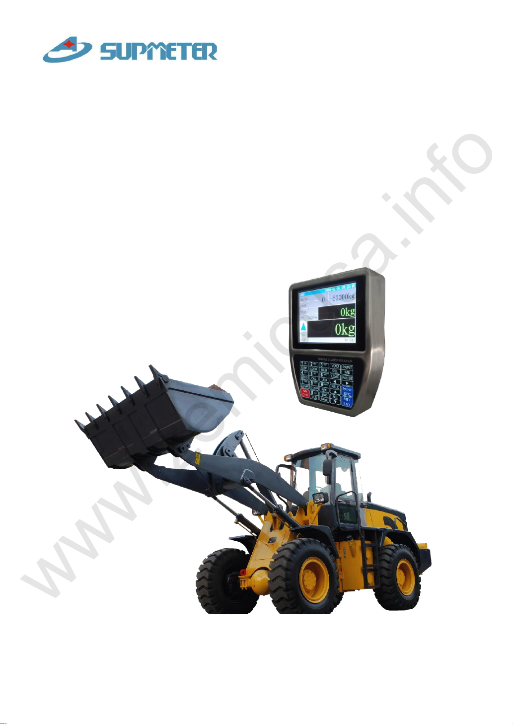
The display information of Bucket Lifting/Declining state, Single-bucket-loading-weight,
Totalized Loading Weight, Positive/Negative Deviation Value, Alarm state, Date/Time and other
auxiliary data are used for adjusting if Single-bucket-loading-weight is valid and the loading
process should be stopped.
Menu&Shortcut mode operation with key tone.
Number, English Alphabet, Simplified/Complex Chinese can be inputted.
The information of User Name, Car.No., Goods No., and Operator No. can be inputted.
Upper/Lower Limit of Single-bucket-loading-weight, Totalized Loading Weight and Date/Time can be set.
Operating Time, Single-bucket-loading-weight, Totalized Loading Weight and Alarm Information can be
recorded automatically.
Using 2 oil pressure sensors for getting higher weighing accuracy than using 1 oil pressure
sensor.
24-bit High-precision and high-speed ∑-△A/D conversion module with 1,000,000 internal code
used and max. sampling frequency 400Hz.
High sampling frequency, multiple digital filter and acceleration compensation algorithm for
ensuring high weighing accuracy in the lifting process of the bucket.
1000 Loading Records can be saved, queried and printed, and each record can contain 50pcs
Single-bucket-loading-weight value.
1000 Reload Records can be saved and open for reloading.
Auto-locking, Key-locking, Key-unlocking, Digital Setting&Calibration and I/O Testing
functions available.
High-Frequency Sampling Multi-filtering Algorithm
Acceleration Compensation High Accuracy&Stablity
www.zemicusa.info

2
Contents
1. SAFETYPRECAUTIONS..............................................................................................................4
2. BRIEF INTRODUCTION............................................................................................................... 5
2.1 OPERATING PRINCIPLE ..........................................................................................................................5
2.2 SYSTEM CONFIGURATION......................................................................................................................5
2.3APPLICABLE SHOVEL LOADERS.............................................................................................................5
3. TECHNICAL SPECIFICATIONS................................................................................................. 6
3.1 TECHNICAL SPECIFICATION OF WEIGHING INDICATOR ..........................................................................6
3.2 TECHNICAL SPECIFICATION OF OIL PRESSURE SENSOR .........................................................................7
3.3 TECHNICAL SPECIFICATION OF POSITION SENSOR .................................................................................8
3.4 SYSTEM ACCURACY..............................................................................................................................8
4. OPERATION INTERFACE ........................................................................................................... 8
4.1 MAIN DISPLAY INTERFACE....................................................................................................................8
4.2 KEYPAD DIAGRAM.............................................................................................................................. 11
4.3 KEYPAD OPERATION............................................................................................................................ 11
4.3.1 Menu Operation & Parameter Setting Operation .......................................................................11
4.3.2 Operation for System Calibration.............................................................................................. 12
4.3.3 Operation in Loading Process ................................................................................................... 12
5. INSTALLATION&CONNECTION.............................................................................................13
5.1 INSTALLATION.....................................................................................................................................13
5.1.1 Structure of Shovel Loader........................................................................................................ 13
5.1.2 Installation of Weighing Indicator............................................................................................. 14
5.1.3 Installation of Position Sensor................................................................................................... 15
5.1.4 Installation of Oil Pressure Sensor ............................................................................................ 16
5.1.5 Cable Laying ............................................................................................................................. 17
5.2 TERMINAL...........................................................................................................................................17
www.zemicusa.info

3
5.3 CONNECTION.......................................................................................................................................18
5.3.1 Oil Pressure Sensor Connector (LC-DN/LC-UP)...................................................................... 18
5.3.2 Position Sensor Connector (POSITION)................................................................................... 18
5.3.3 Power Supply Connector (POWER) ......................................................................................... 19
6. SYSTEM ADJUSTMENT&CALIBRATION PROCEDURE...................................................20
7. FUNCTION&OPERATION.........................................................................................................21
7.1 MAIN MENU........................................................................................................................................21
7.2 PARAMETER SETTING..........................................................................................................................23
7.2.1Weighing Parameters.................................................................................................................. 23
7.2.2 Calibration Parameters .............................................................................................................. 24
7.2.3 Setpoint Parameters................................................................................................................... 24
7.2.4 Alarm Parameters ...................................................................................................................... 25
7.2.5 Communication Parameters....................................................................................................... 26
7.2.6 Display Parameters.................................................................................................................... 26
7.3 SYSTEM CALIBRATION ........................................................................................................................27
7.3.1 Zero Calibration【Zero】......................................................................................................... 27
7.3.2 Zero Compensation【Z.cmp】................................................................................................. 28
7.3.3 Span Calibration【Cal】........................................................................................................... 29
7.3.4 Span Compensation【S.cmp】................................................................................................. 30
7.3.5 Loading Test.............................................................................................................................. 31
8. FAULT TREATMENT ..................................................................................................................32
9. WORKING SPECIFICATION..................................................................................................... 33
9.1 BRIEF DESCRIPTION ............................................................................................................................33
9.2 DETAILED DESCRIPTION......................................................................................................................34
APPENDIXA. PRINT FORMATS..................................................................................................36
APPENDIX B. REGISTER TABLE OF HOST-SLAVE MODBUS[ASCII]................................ 37
www.zemicusa.info

4
1. Safety Precautions
Lithium Battery Installation
A Lithium battery should be equipped in the weighing indicator. If it is not allowed to be
transported together with the product because of embargo, please make a purchase
according to the model offered by us and install it by yourself.
Prohibit using the product under dangerous environment
Prohibit using the product under the dangerous environment with combustible gas and
explosive dust. If you have this need, please use our explosion-proof products.
Avoid using the product under overheated environment
Make sure that the weighing indicator works under the environment with allowed temperature
range to get good performance and long working life.
Please keep the product away from direct sunlight.
Installation & Power Supply of Weighing Indicator
Weld the mounting bracket of the weighing indicator firmly on the metal frame of the shovel
loader driving cab. The installation position should be convenient for operation.
The power switch of the weighing indicator should be turned off and ensure that the power
cables are not charged before DC24V power connection to avoid short circuit fault.
Please make sure that the power supply is correct before power-on.
Installation of Oil Pressure Sensor
Strictly follow the ‘Safety Precaution’described in ‘5.1.4 Installation of Oil Pressure Sensor’.
Install the oil pressure sensors and plate type three-way joints firmly, and seal them as
prescribed to avoid oil leaking.
Installation of Position Sensor
Install the position sensor according to required position and angle, and adjust Detecting
Distance to 3~5mm.
Cable Laying
Oil pressure sensor signal calble and position sensor signal cable should be laid in flexible
pipe for protection, and fix them with nylon strip.
Try to keep signal calbles away from the place with high temperature and possible extrusion,
and reserve enough bending length to avoid being pulled apart.
Environmental Protection
Before the Lithium battery equipped in the weighing indicator being discarded, please
insulate its positive or negative pole, do not put it into fire.
Although the weighing indicator is made of the lead-free components, after used in the
industrial environments, it’s possible to be polluted. So, while being discarded as worthless,
the weighing indicator should be processed lawfully as leady industrial waste for environment
protection.
Other Notes
The installation, wiring and maintenance should be operated by the engineers with the
relevant professional knowledge and safety operation ability. Although being not described in
this manual, the relevant safety operating procedures and standards should be followed.
www.zemicusa.info

5
2. Brief Introduction
2.1 Operating Principle
Shovel Loader Weigher is a dynamic weighing and auto-totalizing equipment installed on shovel
loader without changing the original structure of shovel loader.
When the lift-arm of Shovel Loader is lift to a certain height, the position sensor will trigger the
weighing process, and the weighing indicator will collect the oil pressure signals from lower and
upper oil chambers of arm-lifting oil cylinder. After signal processing and compensation,
Single-bucket-loading-weight will be got and totalized to Totalized Loading Weight automatically,
and the Deviation Value between Totalized Loading Weight and Setpoint, alarm messages will be
displayed. The operator can judge if the present Single-bucket-loading-weight is valid according to
the alarm messages, and confirm the loading weight of last bucket according to Negative Deviation
Value for avoiding overloading. After Totalized Loading Weight reached setpoint, the operator should
stop loading process, save and print Loading Record.
2.2 System Configuration
1 Weighing Indicator with Thermal Printer.
2 Oil Pressure Sensors [0~25MPa].
2 Plate Type Three-way Joints.
1 Position Sensor [Detecting Distance: 5~8mm].
1 Mounting Fitting.
2.3 Applicable Shovel Loaders
Suitable for shovel loader with loading capacity 1~12t:
LiuGong ZL Series.
XiaGong XG Series.
LongKing ZL/LG Series.
XuGong ZL/LW Series.
JinGong ZL/ JGM Series.
LinGong LG Series.
ChengGong ZL/CG Series.
CAT Series……
www.zemicusa.info

6
3. Technical Specifications
3.1 Technical Specification of Weighing Indicator
Product Executing Standard
CMC GB/T7724-2008《Electronic Weighing Meter》PRC National Standard.
OMIL R76: 2006《Non-automatic Weighing Instruments》International Recommendation.
Weighing Accuracy
Accuracy Grade: III .
Number of Nerification Intervals: n=3000.
Error Distribution Coefficient: P=0.5.
Power Supply
Operating Voltage: DC24V±20%.
Max. Power: 10W.
Display
640×480 dots TFT color display screen for English, Simplified/Complex Chinese character
display.
Kaypad
20 keys for Menu&Shortcut mode operation with key tone.
Optional English keypad, Simplified Chinese keypad and Complex Chinese keypad.
Number, English Alphabet, Simplified/Complex Chinese can be inputted.
Auto-locking, Key-locking, Key-unlocking, Digital Setting&Calibration and I/O Testing functions
available.
Weighing Range: 100~12,000kg.
Display Division: 1kg, 5kg, 10kg, 50kg.
Oil Pressure Sensor Input Interface (LD-UP/LD-DN)
2 Oil Pressure signal inputs.
Signal Input Range: 4~20mA.
Excitation Voltage Output: DC12V.
Weighing Signal Sampling Circuit
24-bit ∑-△ADC with 1,000,000 internal code used.
Max. Sampling Frequency: 400Hz.
Zero Drift: ±0.1μV/℃RTI (Relative to Input).
Gain Drift: ±5ppm/℃.
Non-linearity: 0.005%FS.
www.zemicusa.info

7
Position Sensor Input Interface (POSITION)
1 Switch signal Input.
Excitation Voltage Output: DC12V.
Print Port (PRINTER)
RS232.
Digital Communication Interface (COM1)
RS232。
Connectable: IPC/PLC and Wireless Module.
Report Print
1000 Loading Records can be saved, queried and printed, and each record can contain 50pcs
Single-bucket-loading-weight value.
Outline Dimension
168 ×213 ×50 mm (W×H×D).
Cut Dimension
Model Horizontal Panel-mounting: 153 ×77 mm (W×H).
Model Vertical Panel-mounting: 77 × 153 mm (W×H).
Weight Approx. 2.0kg.
Temperature and Humidity
Service Temperature: -20℃to +40℃.
Storage Temperature: -30℃to +60℃.
Relative Humidity: Max. 85%RH.
Protection Level: IP65.
3.2 Technical Specification of Oil Pressure Sensor
Supply Voltage: DC9~36V.
Capacity: 0~25MPa or 0~40Mpa.
Output Signal: 4~20mA.
Long term stability 1year @ +25℃: ±0.3%FS.
Overpressure: 100MPa.
Burstpressure: 200MPa.
Connector: M12×1mm.
Operating Temperature: -40℃~+125℃.
Protection Level: IP67 with connector installed.
Approvals: CE/EMC.
www.zemicusa.info

8
3.3 Technical Specification of Position Sensor
HALL Type Proximity Switches
Operating Voltage: DC5~24V.
Detecting Distance: 5~8mm.
Response Frequency: 5KHz.
Quiescent Current:Max. 2mA.
Thread Size: M8×1mm.
Service Temperature: -25℃~+70℃.
Protection Level: IP67.
Standard Detecting Target: Magnet.
3.4 SystemAccuracy
Accuracy of Single-Bucket -Weight: 0.5%~1.0%FS.
Accuracy of Totalized Loading Weight: ±1.0% (OIMLY(b) Accuracy Grade).
4. Operation Interface
4.1 Main Display Interface
GOODS: 00
OP.: 01
SET: 60.00t
[6]
[7]
[2]
CARNO: 00000
Left[9]/Right[10]
[11]
[5]
4.500 t
[1]
[3]
[4]
[12]
LOAD [LOCK] 05-20-2009 23:59:45
▲
OK
12
+1.200t
61.200t
USER:
ADD
[8]
[13]
www.zemicusa.info

9
No.
Sign
Description
[1]
Working State
LOAD: Loading state.
DEDUCT: Deducting state with flashing yellow background.
PAUSE: Pause state with flashing red background.
[LOCK]: Keypad is locked.
[903] Date Format Hour : Minute : Second
[2]
CARNO
Car No.
[3]
GOODS
Goods Name.
[4]
OP.
Operator Name.
[5]
SET
Setpoint Value.
[6]
Blue ▲
The bucket of shovel loader is below the position sensor.
Blue ▼
The bucket of shovel loader is above the position sensor.
Red ■
Pause State.
[7]
OK
Weighing Normal.
STALL
The operator has released the accelerator of shovel loader in weighing process:
Acceleration Value < [400] Stall Alarm Point.
LOW
Lower Limit Alarm of Single-bucket-loading-weight:
Loading Weight < [401] Load Lower Limit.
HIGH
Upper Limit Alarm of Single-bucket-loading-weight:
Loading Weight > [402] Load Upper Limit.
UND-T
Undertime Alarm: Weighing Time < [403] Min. Weighing Time.
OV-T
Overtime Alarm: Weighing Time > [404] Max. Weighing Time.
[8]
USUER
User Name.
[9]
Bucket Count
The display area of „Bucket Count‟ will change to red background if the key【Void】
is pressed for „Cancel Totalizing‟or „Cancel Deducting‟.
[10]
Deviation Value
Deviation Value = Totalized Loading Weight-Setpoint Value.
[11]
Totalized
Loading Weight
“Last Bucket”Prompt: The display area of „Totalized Loading Weight‟will change
to red background if „Negative Deviation Value<3t‟, it means that the next bucket
may be the last one, the operator should determine the loading weight of the next
bucket according to the actual Negative Deviation Value.
[12]
Single-bucket-
loading-weight
The display area of „Single-bucket-loading-weight‟will change to flashing red
background while alarming.
[13]
TOT
The present Single-bucket-loading-weight has been totalized to Totalized Loading
Weight.
NO TOT
The present Single-bucket-loading-weight has not been totalized to Totalized
Loading Weight because of alarming.
After totalizing, the present Single-bucket-loading-weight can be deducted from
Totalized Loading Weight via the key【Void】.
Refer to parameter [406] „Totalizing/Deducting Permission While Alarming‟.
DED
The present Single-bucket-loading-weight has been deducted from Totalized Loading
Weight.
NO DED
The present Single-bucket-loading-weight has not been deducted from Totalized
Loading Weight because of alarming.
After deducting, the present Single-bucket-loading-weight can be totalized to
Totalized Loading Weight again via the key【Void】.
Refer to parameter [406] „Totalizing/Deducting Permission While Alarming‟.
www.zemicusa.info

10
Press key【Display】to switch the following display interfaces:
AD1: XXXXX
AD2: XXXXX
AD: XXXXX
NET: 0.000t
T2: 0.000s
T3: 0.000s
ACC: 0.0000
T1: 0.000s
V3: 0.000
A0: 0.0000
LR: 1.000
V1: 0.000
Z.CMP: 0
SPAN: 1000
S.CMP: 0
ZERO: 10000
R-AD1: XXXXX
R-AD2: XXXXX
R-AD:XXXXX
R-NET: 0.000t
1. Display Interface A for Testing Oil Pressure Sensor
R-NET: Real-time Weight Value.
R-AD1: Oil Pressure Signal Real-time AD Value from Lower Oil Chamber.
R-AD2: Oil Pressure Signal Real-time AD Value from Upper Oil Chamber.
R-AD: Real-time AD Value = [R-AD1]-[R-AD2].
2. Display Interface B for Testing Oil Pressure Sensor
NET: Single-Bucket-Loading-Weight without Acceleration Compensation.
AD1: Oil Pressure Signal Average AD Value from Lower Oil Chamber in Weighing
Process.
AD2: Oil Pressure Signal Average AD Value from Upper Oil Chamber in Weighing
Process.
AD: AD Value at Weighing Segment = AD1-AD2.
3. Display Interface A for Testing Position Sensor
T1: Time spent by Upper Magnet Block passing by Proximity Switch [s].
T2: Time spent by Proximity Switch running between two Magnet Blocks [s].
T3: Time spent by Lower Magnet Block passing by Proximity Switch [s].
ACC: Acceleration Value at Weighing Segment [dm/s2].
4. Display Interface B for Testing Position Sensor
V1: Average Speed of Upper Magnet Block passing by Proximity Switch [m/s].
V3: Average Speed of Lower Magnet Block passing by Proximity Switch [m/s].
A0: [208] IdleAcc.Value (Acceleration Value at Idle Speed) [dm/s2].
LR: [205] Run Length Ratio.
5. Calibration Parameters display Interface
ZERO: [200] Zero Value.
Z.CMP: [201] Zero Compensation Coefficient.
SPAN: [202] Span Coefficient.
S.CMP: [203] Span Compensation Coefficient.
www.zemicusa.info

11
4.2 Keypad Diagram
4.3 Keypad Operation
If there is not any keypad operation in one minute and it‟s not in the processes of „F2 Calibration‟& „F7 Factory
Adj.‟, the weighing indicator will return to „Main Display Interface‟automatically.
4.3.1 Menu Operation & Parameter Setting Operation
Key Name
Description
【Menu】
Enter Main Menu / Exit.
【Ent】
Enter/Save.
【◄】
Cursor shifts left.
Backspace.
【►】
Cursor shifts right.
【▲】
Cursor shifts up.
Display the previous option.
【▼】
Cursor shifts down.
Display the next option.
【Set】
Setpoint Parameters Setting.
【No.】
Input Car Number.
【0~9】
Number Input.
【A-Z】
English Alphabet Input.
【Print】
Input Method [Number/English/Chinese] Switch.
www.zemicusa.info

12
4.3.2 Operation for System Calibration
4.3.3 Operation in Loading Process
No.
Key Name
Description
1
【Disp】
Display Interface Switch.
2
【Lock】
Key-locking .
Key-unlocking.
3
【Deduct】
Deduct the next Single-bucket-loading-weight from Totalized
Loading Weight.
4
【Zero】
Zero Calibration with unloading and idle speed.
5
【Cal】
Span Calibration with loading and idle speed.
6
【Mode】
Unused.
7
【Z.cmp】
Zero Compensation with unloading and accelerating.
8
【S.cmp】
Span Compensation with loading and accelerating.
9
【Rec】
Query/Print Loading Records.
Reload: Find and open record from the buffering database of
„Reloading Records‟for reloading.
0
【Cls】
Clear Screen without Saving Present Loading Record.
Key Name
Description
【Load】
Enter Loading state (Display blue sign „▲‟).
It‟s necessary to let the bucket of shovel loader stay at the lowest position
before pressing【Load】.
【Finish】
[Save]: Save&Print Loading Record and Clear Screen after Loading
process finished.
[Buffer]: Save Loading Record into the buffering database of
„Reloading Records‟and Clear Screen.
[Cls]: Clear Screen without saving Loading Record.
[Exit].
【Pause】
Enter Pause state (Display red sign „■‟).
【Void】
Cancel Totalizing: After totalizing, the present
Single-bucket-loading-weight can be deducted from Totalized
Loading Weight via this key.
Cancel Deducting: After deducting, the present
Single-bucket-loading-weight can be totalized to Totalized Loading
Weight again via this key.
【Print】
Print Loading Records.
【On/Off】
Press it to turn the power on.
Keep it pressed for 2 seconds to turn the power off.
www.zemicusa.info

13
5. Installation&Connection
5.1 Installation
5.1.1 Structure of Shovel Loader
1: Bucket; 2: Lift-arm; 3: Arm-lifting Oil Cylinder; 4: Oil Connecting Port of Upper Oil Chamber;
5: Oil Connecting Port of Lower Oil Chamber.
Related Operation Terms:
Arm-up: Lift the lift-arm so that the bucket rises.
Arm-down: Put the lift-arm down so that the bucket goes down to the lowest position.
Bucket-up: Flip the bucket upward to the limit position.
Bucket-down: Flip the bucket downward.
Discharge: Flip the bucket downward for discharging materials.
Shovel: Shovel materials into the bucket.
2
3
4
1
5
www.zemicusa.info

14
5.1.2 Installation of Weighing Indicator
1: Fastening Nut for Lateral Rotation; 3: Fastening Nut for Vertical Rotation; 4: Printer
Weld the mounting bracket of the weighing indicator firmly
on the metal frame of the shovel loader driving cab. The
installation position should be convenient for operation.
Suggestion: Install the weighing indicator in the driving cab of
shovel loader and on the side the door will not be opened
frequently.
1
2
3
4
www.zemicusa.info

15
5.1.3 Installation of Position Sensor
Position sensor includes two modules:
Proximity Switch module: Main Mounting Plate with a chute for length adjustment,
Sub-mounting Plate with a chute for angle adjustment and Proximity Switch [Detecting Distance:
5~8mm].
Magnet Module: Thread Pole, Weld-nut, Tight-nut, Nylon Block, Upper Magnet Block and Lower
Magnet Block.
1: Lift-arm Seat; 2: Lift-arm; 3: Main Mounting Plate;4: Sub-mounting Plate; 5: Weld-nut;
6: Thread Pole; 7: Upper Magnet Block; 8: Nylon Block; 9: Lower Magnet Block; 10: Proximity Switch;
11: Fastening Nut for Length Ajustment; 12: Fastening Nut for Angle Ajustment.
Detecting Distance Adjustment:
Method 1: Adjust the distance between the
inductive surface of proximity switch and
magnet block to 5mm.
Method 2: Adjust the distance between the
inductive surface of proximity switch and
Nylon Block to 8mm.
Suggestion: Install the position sensor on the
lift-arm seat and lift-arm which are at the same side
that the weighing indicator installed on.
7
2
1
9
10
11
12
5
3
4
6
8
www.zemicusa.info

16
5.1.4 Installation of Oil Pressure Sensor
1. Intallation Position
The upper oil connecting port and lower oil connecting port of
arm-lifting oil cylinder are the installation positions of oil
pressure sensors.
Suggestion: Install the oil pressure sensors on the arm-lifting
oil cylinder which is at the same side that the weighing
indicator installed on.
2. Safety Precaution
Using a stable and strong base to support the bucket of the
loader for avoiding accidental injury.
In the process of dismounting and mounting, the shovel loader
should be kept at flameout state.
Put a bucket under the oil connecting ports that will be
dismounted for oil collecting.
If the shovel loader has worked for a long time, the oil
temperature in the bucket-lifting cylinder will be very high.
Please let the shovel loader at flameout state for some time
before dismouting to avoide scalding.
Before dismounting the oil connecting port of the upper oil
chamber, let the bucket-lifting action bar stay at the position of
„LIFT‟ for making the upper oil chamber connect with main oil
tank and relief pressure.
Before dismounting the oil connecting port of the lower oil
chamber, let the bucket-lifting action bar stay at the position of
„FALL‟ for making the lower oil chamber connect with main
oil tank and relief pressure.
When somebody stays in driving cab, do not stay under the
shovel loader for avoiding accidental injury.
3. Installation
Wrap some sealing ribbons on the screw of oil pressure sensor
avoid oil leakage, and install it on the three-way joint firmly.
Fix the three-way joint [thickness: 19mm/21mm] and the oil
tube connector on the arm-lifting oil cylinder by the
lengthened screw rods which is about 20mm longer than
original screw rods.
4. Check Oil Passage
Start shovel loader, and lift the lift-arm and bucket with
accelerating for several times.
Check if there is the phenomenon of oil leakage at the oil
connecting ports.
www.zemicusa.info

17
5.1.5 Cable Laying
Oil pressure sensor signal calble and position sensor signal cable should be laid in flexible pipe for
protection, and fix them with nylon strip.
Try to keep signal calbles away from the place with high temperature and possible extrusion, and
reserve their bending length enough to avoid being pulled apart.
5.2 Terminal
4
5
1
3
2
3
4
1
2
2
1
POWER
POSITION
LC-DN
LC-UP
5
2
9
2
3
4
3
6
7
8
1
COM1
ON
OFF
4
5
1
3
2
www.zemicusa.info

18
5.3 Connection
5.3.1 Oil Pressure Sensor Connector (LC-DN/LC-UP)
Oil Pressure Sensor is definable via parameter [106] „Loadcell Channel‟ with default value „2: LC-DN-UP‟:
LC-DN: Connect the oil pressure sensor on the lower oil chamber of arm-lifting oil cylinder.
LC-UP: Connect the oil pressure sensor on the upper oil chamber of arm-lifting oil cylinder.
5.3.2 Position Sensor Connector (POSITION)
No.
Pin
Description
1
SIG-
4~20mA Weighing Signal Input -.
2
SIG+
4~20mA Weighing Signal Input +.
3
EXC-
Excitation Voltage Output - for Oil Pressure Sensor .
4
EXC+
Excitation Voltage Output + for Oil Pressure Sensor (DC12V).
5
SHD
Shield.
No.
Pin
Description
1
VS+
Excitation Voltage Output + for Oil Pressure Sensor ( DC12V).
2
SIN-A
Position Sensor A Signal Input.
3
SIN-B
Position Sensor B Signal Input.
Unused.
4
VS-
Excitation Voltage Output - for Oil Pressure Sensor.
5
SHD
Shield.
POSITION
3
4
1
2
4
5
1
3
2
LC-DN/LC-UP
www.zemicusa.info

19
5.3.3 Power Supply Connector (POWER)
The power switch of the weighing indicator should be turned off and ensure that the power cables are not
charged before DC24V power connection to avoid short circuit fault.
Find the DC24V terminal with relative stable voltage in the driving cab, then connect the terminal „+24V‟of
the weighing indicator to the FUSE, and connect „GND‟ to the metal frame of the driving cab.
Please make sure that the power supply is correct before power-on.
No.
Pin
Wire Color
Description
Voltage
1
GND
Black
DC Input -
DC24V±20%
2
+24V
Red
DC Input +
Note: Reverse polarity protection function available.
2
1
POWER
www.zemicusa.info
Other manuals for BST106-N59
1
This manual suits for next models
1
Table of contents
Other Supmeter Accessories manuals