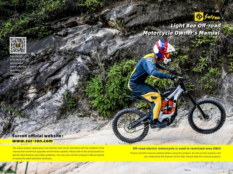
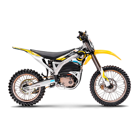
SUR-RON Ultra Bee Series User manual

This manual will provide you a better understanding of your Ultra Bee electric
motorcycle. Please take your time to read this manual and all safety labels
carefully before riding.
This manual contains the most current product information available at the time
of printing, your motorcycle may look and setup differ from the information
supplied in this owner’s manual. Please visit our website www.sur-ron.com for
updates and additional information about your motorcycle.
Ultra Bee Series
Electric Motorcycles
Owner's Manual
Manufacturer: CHONGQING QIULONG TECHNOLOGY CO., LTD
Address: NO. 29, NO. 2 ZHICAI VILLAGE, QIEZIXI STREET,
DADUKOU DISTRICT, CHONGQING, CHINA
Post Code: 400082 Tel:+86-023-68905603
Version: YQ5A-EN-V1.0 Issue Date: 2023.02.20
Scan QR code
for the
latest manual

I n t r o d u c t i o n ..........................................................1 .1
I m p o r t a n t N o t i c e . . . . . . . . . . . . . . . . . . . . . . . . . . . . . . . . . . . . . . . . . . . . . . . . . . . . . . . . 1.1
Tr a n s p o r t i n g . . . . . . . . . . . . . . . . . . . . . . . . . . . . . . . . . . . . . . . . . . . . . . . . . . . . . . . . . . . . . . . . . . . . . . . . 1. 2
Sa fety In form ati on...........................................................2 .1
S a f e t y R i d i n g R e q u i r e m e n t . . . . . . . . . . . . . . . . . . . . . . . . . . . . . . . . . . . . . . . . . . . . . . . . . . . . . 2 .1
Impor tant Information.......................................................................2.3
Location of Important Labels.............................................................2.5
F e a t u r e I n t r o d u c t i o n ...................................................3 .1
Di s p l a y an d Indi c a t o r .....................................................4 .1
Da s h b o a r d O v e r v i e w. . . . . . . . . . . . . . . . . . . . . . . . . . . . . . . . . . . . . . . . . . . . . . . . . . . . . . . . . . . . . 4 .1
F e a t u re S e t t i n g ...........................................................5 .1
D a s h b o a r d S e t t i n g . . . . . . . . . . . . . . . . . . . . . . . . . . . . . . . . . . . . . . . . . . . . . . . . . . . . . . . . . . . . 5 .1
System Feature Mode Display..........................................................5.3
Range varies in Ultra Bee electric motorcycles similarly to how it varies in gas motorcycles. The range variety of
Ultra Bee electric motorcycles comes from the riding application after each full charge. In addition to riding habits,
energy consumption is also affected by environmental conditions (such as extreme cold or hot weather, riding on
steep hill or soft sand etc.). To achieve the maximum range with a single full charge, please pay attention to reduce
the maximum speed, lessen sudden acceleration and maintain a constant speed to ensure the maximum range.
To reach the maximum range, please follow the tips below:
1.Avoid frequent and acute acceleration and braking.
2.Under absolute safe riding conditions, please reduce the riding speed by using throttle to decelerate instead of
pulling the brake lever. When you’re riding the Ultra Bee, if the motorcycle is moving and the throttle is in the
idle position, the energy regenerative brake will reduce the speed of the Ultra Bee and convert kinetic energy to
charge the battery pack.
3.Maintain a correct tire pressure (Please refer to Recommended tire pressure table at page10.9).
4.Remove unnecessary goods and reduce load.
5.The maximum range in winter or summer could be slightly different.
In conclusion, you can estimate the bike range according to the above factors and your riding habits.
V1.0
Ultra Bee R (Road)
ABS(optional)
Headlight,Turn Signals
and RearBrake Light
AT Tires
Note: The range will be varying significantly according to the various tough road conditions
during offroad riding.
Riding Tips For Maximum Range
This manual covers the following electric motorcycles:
\
Headlight,Turn Signals
and RearBrake Light
Offroad Tires
\
Headlight
\
Offroad Tires
Ultra Bee T (Trail) Ultra Bee X (Offroad)
Table of Contents

Feature Introduction...............................................................6.1
Handl ebar controls. ........ ............. ........ ............. ........ ............. .......6 .1
Riding Mode Switch..................................................................................6.4
Parking Brake Operation............................................................................6.4
Battery Pack Removal...............................................................................6.5
Battery Pack Installation...........................................................................6.6
Charger Storage………………………………………………………….......……………....…6.7
St ar t i n g an d O p e ra t i ng ..................................................7.1
C h e c k Be f o r e R i d i n g . . . . . . . . . . . . . . . . . . . . . . . . . . . . . . . . . . . . . . . . . . . . . . . . . . . . . . . . . . . . . 7.1
K e y S w i t c h . . . . . . . . . . . . . . . . . . . . . . . . . . . . . . . . . . . . . . . . . . . . . . . . . . . . . . . . . . . . . . . . . . . . . . 7.1
Steering Lock............................................……………..................................7.2
Seat Lock............................................…………...…........................................7.3
Sta r t i ng and Opera ting. . .... . ..... ..... . .... . ..... ..... . .... . ..... ..... ..... . .... . ...7.3
Temperature Indi cator........................... ............................... ..........7.4
A B S (A n t i - l o c k B ra k i n g Syste m ) . . . . . . . . . . . . . . . . . . . . . . . . . . . . . . . . . . . . . . . . . . . . . . . 7. 5
F r o n t F o r k A d j u s t m e n t . . . . . . . . . . . . . . . . . . . . . . . . . . . . . . . . . . . . . . . . . . . . . . . . . . . . . . . . . . 7.7
Rear Shock Adjustment........................................................................7.8
Po w e r Ma n a g eme n t .........................................................8 .1
B a t t e r y Pa c k . . . . . . . . . . . . . . . . . . . . . . . . . . . . . . . . . . . . . . . . . . . . . . . . . . . . . . . . . . . . . . . . . . . . . . . . . 8 .1
Power Supply and Charging..................................................................8.2
Po w e r Sys t e m Ma n a g e men t ............................................9 .1
P o w e r Syst e m . . . . . . . . . . . . . . . . . . . . . . . . . . . . . . . . . . . . . . . . . . . . . . . . . . . . . . . . . . . . . . . . . . . . . . . . 9 .1
Maintenance............................................................................10.1
Maint ena nce Item ........... ........... ........ ... ........ ........... ........... ........ 10.1
Maintenance Records....................................................................10.1
Sc heduled M aintenance......... .......................................................10.1
Maintenance Sche dule.................................................................. 10.1
Torque Management..............................................................................10.3
Battery Pack..........................................................................................10.5
Brake System.........................................................................................10.5
Brake Fluid Check...................................................................................10.8
Suspension System...............................................................................10.9
Table of Contents
Table of Contents

W h e e l s a n d T i r e s . . . . . . . . . . . . . . . . . . . . . . . . . . . . . . . . . . . . . . . . . . . . . . . . . . .1 0 . 8
Chain.........................................................................1 0 . 9
Headli g h t Adju s t m e nt ....... . . . ........ . . . ........ . . . ........ . . . ........ . . . ......10.10
Light Replacement.............................................................................10.11
Motorcycle Cleaning..........................................................................10.12
Long-term Stora g e . . .......................... . . . . . . . . . . . . . . . . . . . . .................10.13
Ultra Bee Electric Motorcycle Parts....................................................10.14
Fuse..... . . ..... . . ...... . ...... . ...... . ...... . ...... . . ..... . . ..... . . ..... . . ...... . ...... . .10.14
Motorcycle Electrical Circuit Diagram..................................................10.15
Tro u b l e s h o o t i n g ...........................................................1 1.1
U l t ra B e e E l e c t r i c M o t o r c y c l e Tr o u b l e s h o o t i n g . . . . . . . . . . . . . . . . . . . . . . . . 1 1.1
Te m p e rature Prec a u t i o n s . . . . . . . . . . . . . . . . . . . . . . . . . . . . . . . . . . . . . . . . . . . . . . . . . . . . . . . . 1 1.1
Safety Interlock..................................................................................11.2
Precautions for Ultra Bee Electric Motorcycle.......................................11.2
System Warning Message..................................................................11.3
Troubleshooting.................................................................................11.8
Wa r ra n t y I n f o r m a ti o n . . . . . . . . . . . . . . . . . . . . . . . . . . . . . . . . . . . . . . . . . . . . . . . . . . 1 2 . 1
Cond i tion of Wa rranty..... . ..... . ..... . . ..... . ..... . ...... . ..... . ..... . ...... . ..... . 12.1
Period of Warra n t y fo r Su r ron Moto rcycl e.... . . ...... . ...... . . ...... . . ...... 1 2 .1
Pa r t s Cove red by the Wa rranty. . ....... . . . ....... . . . ....... . . ........ . . ....... . . 1 2.2
Wa r ra n t y Labor Cove rage. . . . . . . ..................... . . . . . . . . . . . . . . . ..............12.2
Genera l Exc l u sion from Wa r ra n ty........ . . . . ........ . . . . ......... . . . . ........ . . 1 2 .2
Owne r Re spons i bility .... . ..... . ..... . ..... . ...... . ..... . ..... . ..... . ...... . ..... . ..12.3
Limit a tions on Warranty..... . . ...... . ...... . ...... . . ..... . . ...... . ...... . ...... . . ..12.4
How to Obt ain Wa rranty Ser v ice …..... ..... ..... ..... ..... ..... ..... ..... ..... 12.5
Re p orting Saf ety De fect s ... ..... ..... ..... . .... . .... . .... . ..... ..... ..... ..... . ...1 2 .5
Annex............................................................................1 3 .1
M a i n t e n a n c e R e c o r d S h e e t . . . . . . . . . . . . . . . . . . . . . . . . . . . . . . . . . . . . . . . . . . . . . . .....1 3 .1
After- s a l e s Ser v i c e Re c o rd Sheet... . . . . ......... . . . . . ......... . . . . ......... . . . . 1 3.7
Parameters List ............. ............. ............. ........ ............. ............. ..13.9
Table of Contents
Table of Contents

Important Notice
Congratulations on your decision to purchase a Surron electric motorcycle.
We welcome you to the community of Surron motorcycle riders. You are now the owner of state-of the art electric
motorcycle which, with appropriate care, will bring you pleasure for a long time to come.
This electric motorcycle has been designed and built mainly to withstand the normal stresses and strains of offroad use,
and only authorized for operation on public roads in its homologated version. This motorcycle must only be used as
intended, dangers can be arisen for people, property and the environment through use not as intended.
This manual is designed to provide you with a better understanding of the operation, inspection, basic maintenance
requirements, main functions, helpful tips and explain important safety matters of this electric motorcycle. Please read
through this Owner’s manual carefully, exercise cautiously when riding the motorcycle, and contact Surron or the
authorized Surron dealer if you have any questions. For the latest manual updates and additional information about
your motorcycle, please visit the official Surron website:
www.sur-ron.com
This manual is intended for personal use only, this manual is not intended for commercial use. To protect your investment,
we urge you to take responsibility for keeping your Ultra Bee well maintained. Scheduled service is a must, of course. But
it’s just as important to observe the break-in guidelines, and preform all the pre-ride and other periodic checks detailed in
this manual. This Owner’s Manual should be considered a permanent part of this motorcycle and should remain with it
even if the motorcycle is subsequently sold. Please make sure the next owner well received the manual, it is, by regulation
and law in same countries, regions or states, an important part of the vehicle.
All specifications contained herein are non-binding. This manual contains the word WARNING! to indicate something
that could hurt you or others. The terms “right” or “left” in this manual refer to the rider’s right or left side when
sitting on the motorcycle.
If you have any questions concerning the operation or maintenance of your motorcycle, or if you ever need a special
service or repairs, please contact your authorized Surron Motorcycles dealer, and remember that your dealer knows
your Ultra Bee best and is dedicated to your complete satisfaction. If the dealer’s service cannot meet your
requirement, you can also contact Surron’s After-sale Service Department for help at any time:
service@qiulongtech.com
Happy riding! We wish you enjoy safe and excellent riding at all times.
Introduction
1.1 1.2
_____________________________W a r n i n g _ _ _ _ _ _ _ _ _ _ _ _ _ _ _ _ _ _ _ _ _ _ _ _ _ _ _ _ _
If the power supply, charging system or any other power related equipment is damaged or malfunctioned, please stop
using the charger or vehicle immediately and contact the local Surron authorized dealer or workshop for replacement
or repair.
_ _ _ _ _ _ _ _ _ _ _ _ _ _ _ _ _ _ _ _ _ _ _ _ _ _ _ _ _ _ W a r n i n g _ _ _ _ _ _ _ _ _ _ _ _ _ _ _ _ _ _ _ _ _ _ _ _ _ _ _ _ _ _
This product can expose you to chemicals, including lead and BPA, which are known to the State of California to
cause cancer or birth defects or other reproductive harm. For more information, go to www.p65warnings.ca.gov.
Transporting
It is highly recommended that the electric motorcycle be firmly secured on the transport frame using ratchet straps
while it is being transported. It is also recommended to use soft straps to reduces scratches or other damages.
It is recommended to fix the ratchet straps according to the points shown in the figure. The front two are tied to the
handlebar and the back two are tied to the left and right swing arm. Please do not damage the chain or brake line when
tied the straps. The tie down straps should be at a 45° angle from the motorcycle. Please follow the manufacturer’s
instructions for the ratchet straps you are using.
If you use a truck or motorcycle trailer to transport your Ultra Bee, we recommend that you follow the guidelines below:
1. Use a loading ramp.
2. Secure the motorcycle in an upright position, using motorcycle tie-down straps.
3. Avoid using rope, which can loosen and allow the motorcycle to fall over.
To secure your Ultra Bee, brace the front wheel against the front of the truck bed or trailer rail.
Attach the lower ends of two straps to the tie-down hooks on truck bed or trailer rail. Attach the upper ends of the
straps to the handlebar (one on the right side, the other on the left), close to the fork.
Check that the tie-down straps do not contact any control cables or electrical wiring.
Introduction

Tighten both straps until the front suspension is compressed about half-way. Too much pressure is unnecessary and
could damage the fork seals.
Use another tie-down strap to keep the rear of the motorcycle from moving.
We recommend that you do not transport your Ultra Bee on its side. This can damage the motorcycle.
Safety Riding Requirement
Your electric motorcycle can provide many years of
service and pleasure if you take responsibility for your
own safety and understand the challenges you can
meet while riding. There is a lot you can do to protect
yourself whilst riding. Be aware that offroad racing is a
physically demanding sport that requires more than just
a fine motorcycle. To do well, you must be in excellent
physical condition and be a skillful rider. For the best
results, work diligently on your physical conditioning
and practice frequently.
This electric motorcycle has been designed and built
mainly to withstand the normal stresses and strains of
offroad use. This electric motorcycle is only authorized
for operation on public roads in its homologated
version. This motorcycle must only be used as
intended, otherwise dangers can be arisen for people,
property and the environment through use not as
intended.
You will find many helpful recommendations and safety
instructions throughout this manual. The followings are
a few that we consider to be the utmost important.
Ultra Bee is a high performance electric motorcycle and
should be treated with extreme cautions.
Proper safety gear, including a regional/national
approved helmet, riding boots, eyewear, gloves, and
protective clothing should be worn while riding to
reduce the risk of potential injury, whether you are
practicing to improve your skills, or riding in
competition. We highly recommend the use of full
height motocross boots since the vast majority of
motorcycle injuries are through ankle, leg and foot
impact.
Read all Warning! and instructions in this manual as
well as all the safety labels on the bike before
operating your electric motorcycle.
Never allow a guest to ride your electric motorcycle
without proper instruction.
Ensure you have the legal qualification to ride the
motorcycle before operation.
Never consume alcohol or drugs before operation of
your electric motorcycle. Even one drink or drug can
reduce your ability to respond to changing conditions,
and your reaction time get worse with every additional
drink or drug. So don’t consume alcohol or drugs and
ride, and don’t let your friends or others drink and ride
either.
People unwilling or unable to take responsibility for
their actions should not use this motorcycle. You
assume all responsibility while operating your
motorcycle. The seller assumes no liability for misuse
or operator negligence.
Take time to get to know your Ultra Bee. Because every
motorcycle is unique, take time to become thoroughly
familiar with how this one operates and responds to
your commands before placing your machine, and
yourself, in competition.
1.3 2.1
Safety InformationIntroduction

2.2 2.3
Learn and respect your limits. Never ride beyond your
personal abilities or faster than conditions warrant.
Remember that alcohol, drugs, illness and fatigue can
reduce your ability to perform well and ride safely.
Keep your Ultra Bee in safe condition. Use only Surron
approved parts and Surron Motorcycles genuine
accessories. Maintaining your Ultra Bee properly is
critical to your safety. A loose bolt, for example, can
cause a breakdown in which you can be seriously
injured. Only operate the vehicle when it is in perfect
technical condition, in accordance with its intended use,
and in a safe and environmentally compatible manner.
This motorcycle is a high voltage electric motorcycle,
follow the safety and caution instructions that apply
when using an electric motor. If you smell an unusual
odor coming from the lithium-ion (Li-Ion) battery, park
your Ultra Bee in a safe place outside and away from
flammable objects, and then turn off the key switch.
Contact your local authorized Surron dealer to help you
to inspect your Ultra Bee immediately.
Prior to each use, the rider must check everything listed
in the “Check before Riding” section on page 7.1, and
the charge level of the battery pack as indicated on the
dashboard display.
It is important to keep your motorcycle properly
maintained and in safe riding condition. Having a
breakdown can be difficult, especially if you are
stranded offroad far from your base. To help avoid
problems, inspect your motorcycle before every ride and
perform all recommended maintenance according to
the maintenance schedule and adjustment requirements
listed in this manual. Be sure you understand the
importance of checking all items thoroughly before
riding. If your Ultra Bee is offroad version, please
understand your motorcycle is designed and
manufactured for offroad use only. The tires are not
made for paved surface use and the motorcycle does
not have turn signals or other features required for use
on public roads. If you need to cross a paved or public
road, use other authorized vehicle to transporting or get
off the motorcycle and push your motorcycle to your
destination.
The rear brake lever is located on the left side of the
handlebar. Because this electric motorcycle does not
have a manual transmission, and thus there is no clutch
and gear shifting.
Modifying the motorcycle is prohibited, as otherwise
safe operation cannot be guaranteed. Modification such
as using opening Li-ion battery pack, motor, and MCU
may render the motorcycle unsafe and may cause
severe personal injury. The manufacturer does not hold
liable for non-approved modifications.
Be very careful when loading or adding accessories to
your motorcycle. Large or heavy items may adversely
affect the handling and performance of your
motorcycle.
Important Information
Several important operational considerations are listed
below:
Always turn the key switch A and motor stop switch B
to the OFF position when not actively riding. It is
extremely easy to forget that the motorcycle is still in
standby mode because it is completely silent. An
accident might occur if the motorcycle is left powered
on while getting on or off the motorcycle.
Turn the motor stop switch B OFF and make sure the
READY indicator is not light up when pushing or moving
the motorcycle.
Use the parking brake C when you are stopped on a
ramp or steep hill. Do not hold partial throttle to keep
the motorcycle stationary on a ramp or steep hill, as it
can trigger the locked rotor protection which cause the
motorcycle to slip back.
A rechargeable Lithium-ion battery is installed in the
motorcycle. The battery pack is located under the seat,
please recharge the battery pack of your electric
motorcycle after each use. Once fully charged, please
disconnect from AC power supply. Make sure that the
charging is carried out in a safe and open space or
under monitor.
When unplugged the battery power plug while the key
in the OFF position, the motorcycles electronic
components will consume a small amount of power and
the battery pack will drain extremely slowly. If you
don’t ride for a long-term period of time (30 days or
more), you may need to charge the electric motorcycle
for a few hours prior to your next ride.
The battery pack will be damaged if it is stored for a
long time under low power.
B
A
C
Safety InformationSafety Information Safety Information

2.4
A
B
A
B
A
Battery pack
Warning Label B
High Voltage
Warning Label A
Battery pack
Warning Label C
Location of Important Labels MCU recommended torque label A,MCU info label B
Frame Nameplate A, VIN label B
Motor Serial Number A
Safety InformationSafety Information Safety Information
__________C a u t i o n __________
Only charge the Ultra Bee lithium-ion battery pack
with the manufacturer’s genuine charger or Surron
approved charger. Only use the battery pack while it is
inside the vehicle.
The battery pack does not require nor benefit from
deep discharging. To get the maximum battery pack
lifecycle, recharge the battery pack after each ride.
Constantly leaving the battery pack in a deep
discharging state will damage the battery cell.
Failure to follow instructions of the battery pack
storage and charging as written in this manual may
void the warranty of your Ultra Bee electric motorcycle.
These guidelines have been rigorously tested to
ensure maximum battery pack efficiency and service.
__________N o t e _ _ _ _ _ _ _ _ _ _
The battery pack contains components and elements
that might harmful to the environment, so please
dispose the battery pack properly and in compliance
with the applicable regulations. Never throw the
battery into the household trash bin.
2.5

2.6 2.7
If your vehicle has T-BOX installed, please visit the
Download Center of Surron official website. Download
the Surron App, install and connect the device to use.
Vehicle VIN Label
T-BOX(Telematics BOX)
SIM Label
T-BOX(Telematics BOX)
S/N Label
Scan this QR
code to enter
the Download
Center.
Safety InformationSafety Information Safety Information
A. Mirrors
This Ultra Bee electric motorcycle is equipped with convex
mirrors. A convex mirror has a curved surface in order to
offer a greater field of view than a similar flat mirror.
However, the greater field of view makes objects seem
further away than they really are. Care must be taken
when judging the distance of objects seen in these mirrors.
B. Rear Brake Lever
For description and operation, please refer to “Feature
Introduction”, on page 6.1.
C. Parking Brake Lever
For description and operation, please refer to “Feature
Introduction”, on page 6.1
D. Rear Brake Fluid Reservoir
For description and operation, please refer to
“Maintenance”, on page 10.5.
E. Left Combination Switch
For description and operation, please refer to “Feature
Introduction”, on page 6.1.
F. Dashboard
For description and operation, please refer to “Display
and Indicator”, on page 4.1. and “Feature Setting”,
on page 5.1.
G. Key Switch
For description and operation, please refer to “Starting
and Operating”, on page 7.1.
H. Front Brake Fluid Reservoir
For description and operation, please refer to
“Maintenance”, on page 10.5.
I. Front Brake Lever
For description and operation, please refer to “Feature
Introduction”, on page 6.3.
J. Right Combination Switch
For description and operation, please refer to “Feature
Introduction”, on page 6.3.
K. Throttle Grip
For description and operation, please refer to “Feature
Introduction”, on page 6.3.
L. USB Port
5V 2.4A USB A port
Feature Introduction
3.1 3.2
Feature Introduction

A. Headlight
For headlight operation, please refer to “Feature
Introduction”, on page 6.1.
For headlight replacement, please refer to
“Maintenance”, on page 10.11.
For headlight alignment, please refer to
“Maintenance”, on page 10.10.
B. Front Turn Signals
For turn signals operation, please refer to
“Feature Introduction”, on page 6.1.
For turn signals replacement, please refer to
“Maintenance”, on page 10.11.
C. Integrated Battery Charging Port
For description and operation, please refer to “Power
Management”, on page 8.1.
D. Rear Turn Signals
For rear turn signals operation, please refer to “Feature
Introduction”, on page 6.1.
For rear turn signals replacement, please refer to
“Maintenance”, on page 10.11.
E. Brake/Tail/License Plate Light
For brake/tail/license plate light replacement, please
refer to “Maintenance”, on page 10.11.
F. Side Stand Switch
This switch is a safety sensor that prevents accidently
incorrect motorcycle operation when the side stand is
down.
G. Side Stand
The side stand supports the motorcycle when parked.
The key switch should be in the OFF position when
parked.
H. Chain Adjuster
Located on left and right side of the swingarm, for the
tension adjustment procedure, please refer to
“Maintenance”,on page 10.9.
3.3 3.4
E
D
F
H
G
A CB
Feature Introduction Feature Introduction
__________Caution__________
Park the motorcycle only on a flat firm surface,
otherwise the motorcycle could fall over and causing
damage.

3.5 3.6
B CA
D
E
G F
A. Seat Lock
For description and operation, please refer to “Starting
and Operating”, on page 7.3.
B. Rear Shock Absorber
For description and operation, please refer to “Starting
and Operating”, on page 7.8.
C. Steering Lock
For description and operation, please refer to “Starting
and Operating”, on page 7.2.
D. Front Fork
For description and operation, please refer to“Starting
and Operating”, on page 7.7.
E. MCU
For description and operation, please refer to “Power
System Management”, on page 9.1.
F. Battery Pack
For description and operation, please refer to “Power
Management”, on page 8.1.
G. Motor
For description and operation, please refer to “Power
System Management”, on page 9.1.
Feature Introduction Feature Introduction

E
Display and Indicator
4.1 4.2
A. Clock
The clock displays time in 24-hour mode.
B. Charge Indicator
This indicator and readout display the amount of
energy remaining in the battery pack, which is similar
to the fuel gauge on a gasoline powered motorcycle.
C. ASR Indicator
This indicator displays the current ASR (Traction Control)
level, and it disappears when ASR is turned OFF.
D. Transmission Ratio Display
It displays the current transmission ratio of Ultra Bee
electric motorcycle.
E. Temperature Indicator
The temperature indicator is on the left side of the
dashboard LCD display, indicating the overall
temperature of the motor, MCU and battery pack. When
the temperature of one of these components exceeds
the maximum temperature limitation, the temperature
indicator will start to flash. For description and
operation, please refer to “Starting and Operating”,
on page 7.4.
F. Riding Mode
This area displays the riding mode (S, E, D)
corresponding to the Riding mode of SPORT, ECO and
DAILY. The Riding mode switch is located on the right
handlebar.
For description and operation, please refer to “Feature
Introduction”, on page 6.4.
G. Speedometer
The speedometer is digital display in either kilometers
per hour (km/h) or miles per hour (mph).
For description and operation, please refer to “Feature
Setting”, on page 5.1.
H. Odometer
The odometer displays the total distance the motorcycle
has been ridden in kilometers or miles.
I. Warning Code Display
When the system fault has been detected, the
corresponding Warning Code will be displayed on this
area. For Warning Code explanation, please refer to
"Troubleshooting" on page 11.4.
Display and Indicator
Dashboard Overview

4.3 4.4
A B C D E F
G
H
I
J
Display and Indicator Display and Indicator
A. Left Turn Signals Indicator
Once the Left Turn Signals switch is toggled,
the Left Turn signals remains flashing until
the Turn signals request has been canceled.
B. Low Power Indicator
This indicator displays the condition of the
power system, remain flashing when power
system enter low power mode.
C. System Warning Indicator
The indicator illuminates when a fault has
been detected. Please refer to
“Troubleshooting” for detailed Warning
Code, on page 11.4.
D. Reverse Mode Indicator(R)
The indicator illuminates when reverse mode
is ready to use; the indicator flash when the
reverse mode is in use; the indicator
disappears when the reverse mode is OFF.
E. ABS(Anti-Lock Brake System)Indicator
The indicator illuminates or flashes when ABS
system fault has been detected or it is been
turned OFF. For description and operation,
please refer to “Starting and Operating”, on
page 7.5.
F. Right Turn Signals Indicator
Once the Right Turn Signals switch is toggled,
the Right Turn signals remains flashing until
the Turn signals request is canceled.
G. Low Energy/Charging Indicator
When the energy remaining in the battery pack is low
(State of Charge (SOC) < 20%), the low energy
indicator illuminates. If the energy remaining
in the battery pack is very low (SOC <5%), the
indicator flashes. The indicator also flashes
when the motorcycle is being charged.
H. ASR (Traction Control System) Indicator
The ASR (Acceleration Slip Regulation) traction control
feature is turned ON and OFF by the ASR button, and
the ASR indicator illuminates when activate
and goes off if ASR has been turned OFF.
When the ASR indicator flashes means the
speed sensor or the ASR feature is
malfunctioned. Please check whether the gap between
the wheel speed sensor and the speed sensor ring is in
the range of 0.8 ~ 1.2mm, and whether the wheel speed
sensor is damaged.
I. Ready Indicator
The indicator illuminates mean the motorcycle
is ready to go.Twist the throttle when the
indicator illuminates, the motorcycle will
move.
J. High Beam Indicator
When the headlight high beam is ON, this
indicator illuminates.

Feature Setting
5.1 5.2
A
B
__________Attention__________
When the speed display on the speedometer is
higher than the actual speed, reduced the
transmission ratio until meet the actual speed;
increase transmission ratio if speed display on the
speedometer is less than the actual speed.
__________Caution__________
Please change the transmission ratio with cautious.
(Stock original transmission ratio is 1.0).
1.When the motorcycle key switch is in OFF, press and
hold the M button and turn the key switch ON whilst
still holding the M button for more than 2 seconds, then
select between Miles per Hour (mph) and Kilometer per
Hour (km/h).
2. is displayed when Miles per Hour (mph) has
been selected.
3. is displayed when Kilometer per Hour (km/h)
has been selected.
Display - Transmission ratio
Transmission ratio setting:
When the motorcycle key
switch is in OFF, press and hold the S button and turn the
key switch ON whilst still holding the S button for more
than 2 seconds, then enter into the transmission ratio
setting mode, and “ “ indicator flashes. To
adjust the transmission ratio by momentarily press M
button or S button. Momentarily press S button to
decrease transmission ratio by 0.1 till lowest transmission
ratio; Momentarily press M button to increase by 0.1 till
highest transmission ratio. Press and hold M button for
more than 2 seconds to save the current setting
(automatically save and exit transmission ratio setting
mode after no action for 5 seconds).
Time Display
Clock Setting:
Press and hold the M button for more than 2 seconds
after the motorcycle is switched ON, speed is 0km/h to
enter the clock setting mode, the “Hours” will start to
flash and ready to adjust; momentarily press M button
again, the “Minutes” will start to flash and ready to
adjust; momentarily press M one more time will quit
clock setting mode.
When “Hours” is flashing and ready to be set, momentarily
press S button will increase 1 hour, press and hold S
button increase will increase “Hours” gradually until
Feature Setting
Dashboard Setting
The features and displays on the dashboard can be
customized to your personal preferences by using the A
and B buttons on the Handlebar Control.
A. Mode Button (M)
By momentarily pressing or holding the M button you
can reset fields and toggle through the menus and
display options.
B. Select Button (S)
To select the corresponding feature by pressing S
button when entered the feature menu.
Display - Odometer
Select total or trip mileage:
1. To select the display of total or trip
mileage , momentarily press the M button
when the dashboard in main display mode and the
speed of the motorcycle is 0km/h.
2. When Trip mileage displayed, and the motorcycle
speed is 0km/h, the speedometer display area shows
the Top speed; the speedometer will instantly display
the current speed when the motorcycle starts to
moving.
Reset trip mileage and maximum speed:
To reset the trip mileage and maximum speed,
simultaneously by pressing and holding the S button
for more than 2 seconds in the trip mileage mode,
when the dashboard in main display mode and the
speed of the motorcycle is 0km/h.
Unit Display – Speed
Select Miles per Hour (mph) or Kilometer per Hour
(km/h) :

For example, when feature B2 shown on the
dashboard, momentarily press Ready button in Right
Combination Switch to switch between different setting
levels, such as B3, B4, B0, B1, etc. Switch in sequence
until find the correct setting level. If there is no action
for a long time, system will exit automatically.
The available features are listed below:
1. Level setting for brake energy regenerative feature
(B0 B1 B2 B3 B4 B5) Factory default at B2 (feature is
disabled in B0, and strengthens in turn from B1 to B5).
2. Level setting for coast energy regenerative feature
(E0 E1 E2 E3 E4 E5) Factory default at E3 (feature is
disabled in E0, and strengthens in turn from E1 to E5).
3. Level setting for ASR feature (A1 A2 A3) Factory
default at A2 (feature strengthens in turn from A1 to
A3).
4. Setting for brake override feature (P0 P1) Factory
default at P0(feature is disabled in P0, and activated in
P1).
5. Setting for tilt protection feature (C0 C1) Factory
default at C1(feature is disabled in C0, and activated in
C1).
6. Diagnostic report feature (T0 T1) Factory default at
T0 (feature is disabled in T0, and activated in T1).
7. Throttle sensitivity adjustment feature (F1 F2 F3)
Factory default at F1 (feature sensitivity is strengthens
in turn from F1 to F3, ONLY available in SPORT mode).
8. Charging power adjustment feature(U1 U2 U3)
Factory default at U3 (U1 means the charging power is
480W; U2 is 750W; Maximum charging power U3 is
1100W).
Exit System Feature Mode Setting (X):
1. Make sure the Key Switch is ON and lift the side
stand will exit System Feature Mode Setting
2. If no action in 10 seconds, it will exit System Feature
Mode Setting automatically.
5.3 _ _ _ _ _ _ _ _ _ _ W a r n i n g _ _ _ _ _ _ _ _ _ _
It is recommended to turn off the tilt protection in
off road environment, to avoid the loss of power
due to the triggering of tilt protection when
performing some jump or stunt. To extend the life
span and the safety of the battery pack, when
battery state of charge(SOC) is over 95% or
battery internal temperature exceed the working
condition temperature between 0°C to 50°C, the
energy regenerative system will be disabled.
5.4
BA
ASR Display Explanation
display(ASR turned ON level3)
Feature Setting Feature Setting
release S button. After finish the “Hours” adjustment,
momentarily press M button will save current setting
and enter “Minutes” setting.
When “Minutes” is flashing and ready to be set,
momentarily press S button to increase 1 minute, press
and hold S button increase will increase “Minutes”
gradually until release S button. After complete the
“Minutes” adjustment, momentarily press M button to
save the current setting and quit clock setting mode.
ASR (Traction Control
System) Indicator
When you use the ASR button to turn the ASR ON and
OFF or select the ASR setting level, the ASR level will
display as follow:
For description and operation, please refer to “Feature
Introduction”, on page 6.2.
System Feature Mode Display
Note: Display one English letter in field A (Different
English letters are displayed according to different
feature modes).Display one number in field B (Different
Numbers are displayed according to different feature
modes).
System Feature Mode Setting:
When the motorcycle is in its normal operating mode or
with side stand down, press and hold ASR button on
the Left Combination Switch and Ready button in the
Right Combination Switch at the same time over 2
seconds to enter the system feature setting mode.
After enter the system feature setting mode:
Momentarily press ASR button on the Left Combination
Switch to switch between each feature, such as B2, E3,
P0, etc.
display(ASR turned ON level3)
non display(ASR turned OFF)

Handlebar Controls
EB D FA H
GC
Feature Introduction
6.1 6.2
J
I K
A. Rear Brake Lever
When you pull or squeeze the brake lever, it will control
the rear brake system. When braking, the throttle should
be in the idle position. The brake lights are also lit.
B. Parking Brake
When parking on a steep hill or ramp, apply the
parking brake to prevent the motorcycle from rolling
back. For instructions and operations, please refer to
page 6.4 of "Feature Introduction".
C. Headlight High/Low Beam Switch
When the switch is pressed, the headlight changes from
low beam to high beam. It remains in the selected
position until it is switched back. When in the high
beam position, the high beam indicator on the
dashboard lights up.
D. Turn Signals Switch
When you push the Turn signals switch to the left or
right, the corresponding front and rear Turn Signals will
flash. When the Turn signals light switch is turned on,
the Turn signals indicator on the dashboard light up.
Be sure to turn and change lane operations in
accordance with the local law and regulations. Unlike
cars or other vehicle, Turn Signals can only be manually
canceled on the Ultra Bee motorcycle. Press the switch
and it will return to the OFF (middle) position.
E. Horn Button
When the Key switch is in the ON position, the horn will
operate when the button is pressed. The Ultra Bee
motorcycle is very quiet when riding, and the horn can
be used to warn pedestrians, cyclist, driver or any other
personal present.
F. R\S Button (Reverse Mode\ASR quick setting)
Reverse mode: When the throttle is in fully closed
position, press and hold the R/S button, the reverse
indicator R on the dashboard will illuminates, and the
Ultra Bee motorcycle will enter the Reverse mode.
Only when the R/S button is released and the throttle is
returned to fully closed position, the system will exit
the reverse mode and the forward mode will be
functionally again.
The Ultra Bee motorcycle will “shake” to reminder the
rider when enter or exit Reverse mode. ASR quick
setting:
1. Quick press R/S button once to display current ASR
level.
2. Quick double press R/S button to shift one ASR level,
keep double press to switch in cycles.
G. Hazard Warning Lamp Switch
When the switch is pressed, the front and rear turn
signals are all flash to warn others of situations, which
include needing to stop or park under emergency
conditions. When pressed again, the switch resets and
the turn signals go out. (This is the headlight high
beam switch on Ultra Bee X version)
H. ABS Button
For operations and instructions, please refer to " Starting
and Operating" page 7.5.
I. Brake Lever Adjuster
Adjustment nut used to set brake lever position, by
using 2.5mm hex key and 8mm open end wrench to
adjust the brake lever position to fit the rider’s riding
habit.
J. Overtaking Button
This switch is self-return switch button. When the
headlight is in the low beam position, press the button,
the high beam is on, high beam indicator on the
dashboard also illuminates. Release the button, high
beam is off.
K. ASR (Traction Control System) Button
The Acceleration Slip Regulation (Traction Control
System) can be adjusted by the ASR button in the left
combination switch.
ASR button is located behind the left combination
switch, trigger switch. When ASR is off:
1. No action: ASR off.
2. Press and holding: ASR is turned on and active in the
previous setting ASR level, release the button will
disable the ASR.
3. Quick press 3 times: ASR is turned on, and locked in
active state; quick press 3 times again, ASR will be
turned off.
Feature Introduction

6.3 6.4
A
B
ML
N O P
L. Front Brake Lever
When you pull or squeeze the brake lever, it controls
the front braking system. When braking, the throttle
should be in the idle position. The brake lights are also
lit.
M. READY Button
When the motorcycle is in ready condition, press the
button will make the motorcycle enter the riding state,
The READY indicator also illuminates.
N. Motor Stop Switch
When pressed A on the top of the switch, it will cut off
the power supply for the power train. The MCU remains
in the no power output state until the B on the bottom
of the switch is pressed. The switch does not switch off
all operational functions, only cut off the power to the
power train.
O. Riding Mode Switch
The Riding Mode Switch toggles between SPORT, ECO
and DAILY riding modes. For instructions and
operations, please refer to page 6.4 of "Feature
Introduction".
P. Throttle Control
When the motorcycle is in READY state, twist the
throttle in a counter-clockwise rotation start the motor
and accelerate the motorcycle in a forward direction.
Release the throttle and it snaps back to the idle
position will stop the motor, decelerate the motorcycle.
The throttle sensitivity level can be adjusted in the
System Feature Mode, please refer to page 5.3 for
details.
Riding Mode Switch
The Riding mode includes SPORT mode S, DAILY mode D
and ECO mode E. You can switch among Riding modes
while riding, and there will be specific icon showing on
the dashboard.
A. SPORT Mode S
Slide this switch to the top to enter the SPORT mode.
This mode has the strongest power output and
acceleration ability. It is highly recommended being
used in trail or any off-road terrain. Users are strongly
recommended to use this mode only after getting
familiar themselves with the Ultra Bee motorcycle.
B. ECO Mode E
Press this switch in the middle to enter ECO mode. In
this mode, the power and acceleration ability are much
reduced, the Ultra Bee motorcycle is much easier to ride
and maximized the cruise range.
C. DAILY Mode D
Slide this switch to the bottom to enter Daily mode. In
this mode, the power output is reduced and acceleration
is more gent, so that is suitable for daily riding.
Parking Brake Operation
Ultra Bee electric motorcycle is equipped with a parking
brake. When triggered, the parking brake system will
prevent the electric motorcycle from rolling forward or
backward. There are three gears for parking brake
intensity, which should be selected according to
different scenarios.
A. Parking Brake On
Squeeze the rear brake lever and push the parking
brake lever, the brake gear will into the parking brake
limiting slots, and release the rear brake lever.
B. Parking Brake Off
Squeeze the rear brake lever, the parking brake lever
will automatically pop out of from the parking brake
limiting slots.
Feature Introduction Feature Introduction
A
C
B

6.5 6.6
_ _ _ _ _ _ _ _ _ _ W a r n i n g _ _ _ _ _ _ _ _ _ _
Do not change the installation steps of the
communication plug and the power plug at will.
Remember not to connect or remove the power plug
while the communication plug is still plugged in. As the
battery pack is a high-voltage components, wrong
installation steps may cause severe damage or even
personal injury.
B
C
③
②
A
C
B
③
①①
②
Feature Introduction Feature Introduction
Battery Pack Removal
1. Insert the key into the seat lock switch A and turn the key
according to the arrow direction to unlock the seat lock.
2. After the seat springs up, lift the rear end of the seat
up slightly, and then pull the seat backward to remove
the seat according to the arrow direction.
3. Press the battery compartment cover ① down, push
two battery compartment cover clamp toggles ②
downward and flick the latch of two clamps ③ forward
respectively to disengage the latch from the hook, and
then open the battery compartment case cover
according to the diagram.
4. Remove the blue communication plug C and then the
orange power plug B. Make sure to disconnect the plug
carefully and vertically to avoid damaging the connectors.
5. Lift up the battery pack to remove the battery pack
and store it in a safe place.
Battery Pack Installation
1. Open the battery compartment cover and put the
battery pack in the battery compartment.
2. Connect the orange power plug B first, and then the
blue communication plug C. Make sure to insert the
plug carefully and vertically to avoid damages.
3. Close the battery compartment cover according to
the arrow showing on the diagram and press the
battery compartment cover ② down, then flick the latch
of two clamps ③ backward respectively to engage the
hook in place, and push two toggles ① upward to lock
the battery compartment cover.
4. Push the positioning slot at the front of the seat into
the front positioning bushing on Ultra Bee body, then
align the hook in the middle of the seat with the
positioning bracket on subframe. After that, push the
seat forward in the direction of the arrow shown in the
figure to install the positioning slot and hook in place.
Press the rear end of the seat down to lock the seat.
__________Warning__________
Before removal or installation of the battery pack
on the Ultra Bee motorcycle, the key switch must be
in the OFF position, so that the whole motorcycle is
in no power condition.

Check Before Riding
Before operating the electric motorcycle, please check
the following items to ensure that the Ultra Bee electric
motorcycle is in operational condition:
Battery pack
Check that the battery level displayed on the battery
pack or dashboard is sufficient enough to support your
riding. We recommend you to fully charge before your
next trip.
Chain
Check the chain tension and condition. Adjust or
replace if necessary. Please refer to "Chain" on page
10.9.
Brake system
Squeeze the brake lever and push the motorcycle to see
if the front and rear wheels are fully locked. You should
be able to lock the wheels completely by braking.
Throttle
When the key switch is in the off position, twist the
throttle and release it to check whether the throttle is
move smoothly and return to idle freely.
Tires
Check the tire pressure and tread depth of the tires.
Check the cold tire pressure, maintain the correct tire
pressure, and check for damage and abnormal wears of
the tire surface. As described on page 10.1, when the
tread depth is reached the warning mark on the tire,
please do not ride the motorcycle and replace the tire
immediately.
Electrical System
Check whether the headlight, turn signals lights and
brake lights/taillights are functioning properly.
Key Switch
_ _ _ _ _ _ _ _ _ _ W a r n i n g _ _ _ _ _ _ _ _ _ _
Unusual tire pressure is a common reason that
cause of tire failure, and may cause severe tires
issues or loss control of the electric motorcycle,
which may result in serious personal injury. Check
the tires regularly to ensure perfect tire condition.
6.7 7.1
_ _ _ _ _ _ _ _ _ _ _ _ N o t e _ _ _ _ _ _ _ _ _ _ _ _
When installing the seat back in, make sure that
the charger and cables are stored secured in place
to avoid damages to the cable or charger.
A B
Charger Storage
Feature Introduction
In order to provide Ultra Bee rider a better experience,
there is a storage room designed on the Ultra Bee,
which can be used to store the charger or other items.
1. Remove the seat. For description and operation,
please refer to “Battery pack removal”.
2. Remove the input cable A from the charger and place
it into the storage compartment.
3. Place the charger B in the storage compartment
upside down (As shown in the figure, the direction of
the charger is indicated by arrows and labels.) and
store the output cable of the charger at the back of
storage compartment. There is positioning structure of
the charger designed for fixing the charger inside the
storage compartment.
4. At last, install the seat back on the motorcycle, make
sure the buffer foam on the bottom of the seat is fully
secured with the charger. For description and how to
install the seat, please refer to "Battery pack installation".
Starting and Operating
This manual suits for next models
3
Table of contents
Other SUR-RON Motorcycle manuals