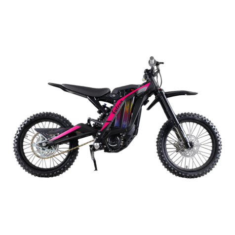
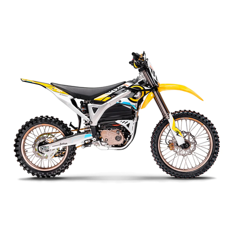
SUR-RON STORM BEE User manual

Cover Image
This manual will provide you a better understanding of your electric motorcycle.
Please take your time to read this manual carefully and all safety labels before riding.
Table of Contents
Introduction............................ 1.1
Important Notice................................ 1.1
Transporting.................................1.2
Safety Information...................... 2.1
Safe Riding Requirement................. 2.1
Important Information...............................2.2
Location of Important Labels.......................2.4
Operation and Component Locations........................3.1
Display and Indicator.....................4.1
Dashboard Overview.....................................4.1
Feature Setting 功能设置.........................5.1
Dashboard Setting.....................................5.1
System Feature Setting 系统功能设置................................................ .......... 5.3
Feature Introduction 功能介绍...................................................6.1
Handlebar Controls....................................... .......... 6.1
Riding mode Button................................................. 6.4
Parking Brake Operation............................................... ... 6.4
Battery Pack Disassembly.................................................6.5
Battery Pack Assembly...................................... 6.6
Starting and Operating..................................... 7.1
Check before riding................................ 7.1
Key switch/ Steering lock................................. 7.2
Riding................................................. 7.3
Parking.............................................. 7.3
Temperature indicator............................................. 7.4
ABS(Anti-lock braking system)...................................7.5
Front fork adjustment................................. 7.7
Rear shock adjustment................................................. 7.10

Power management..... 8.1
Battery Pack................................................ ................ 8.1
Power and charging................................. 8.2
Power system management................................................... 9.1
power system........ 9.1
Junction Box....................................... 9.1
Maintenance Your Motorcycle................................. 10.1
Maintenance Items...................................... 10.1
Maintain Records....................................................10.1
Regular Maintenance..................................................... 10.1
Maintenance Plan....................................... ........... 10.1
Torque Management............................................... 10.3
Battery Pack................................................................ 10.5
Braking System..................................................................... 10.5
Suspension system ......................................................... 10.8
Wheels and Tires..................................... ....10.8
Chain................................................ ..................... 10.9
Reduction reduction gearbox oil................................................ ..................... 10.10
Headlight Adjustment ................................................ ................ 10.11
Light Bulb Replacement...............................10.12
Motorcycle Cleaning...................................................... 10.12
Parking and Long-term Storage..................................... 10.13
Electric motorcycle parts................................. 10.14
Fuse......................................................... ........10.14
Whole motorcycle electrical schematic diagram.....................................10.16
Troubleshooting.......................................11.1
Electric Motorcycle Troubleshooting................................................ ......... 11.1
Precautions for hot and cold weather.............................................. 11.1
Safety Interlock............................................11.2
Electric Motorcycle Precautions...................................................... 11.2
System warning message.............................................. ...... 11.3
General troubleshooting...................................................... 11.6
Warranty and after-sales information................................. 12.1
Limited Warranty conditions.................................... .............. 12.1
Sur-Ron Warranty period for sales motorcycles................................................ ................................12.1
Parts Covered by warranty ................................................ ..................... 12.1
Warranty hours.................................... ........... 12.1
Limitations of the limited warranty....................................... ..................... 12.2
Motorcycle owner responsibility................................................. .......12.2

Warranty limitations .................................................................... 12.3
How to obtain warranty service .................................................................12.4
Schedule........... 13.1
Maintenance Record Sheet................. 13.1
After-sales record sheet................. 13.7
Comparison table of domestic motorcycle parameters................................................... 13.11
Comparison Table of Export model parameters..................... 13.12
Domestic Distributors.............................................. 13.13
Introduction
1.1
Important Notice
Congratulations and thank you for purchasing SURRON STORM BEE electric motorcycle. We
sincerely welcome you to the community of SURRON electric motorcycle riders.
This manual is designed to provide you with a better understanding of the operation,
maintenance requirements and troubleshooting of your electric motorcycle. Please take your
time to read this manual carefully as well as all safety labels before riding. Please DO NOT use it
until you understand the basic operation and features of the STORM BEE electric motorcycle.
You can also find this manual to download on our official website http://www.sur-ron.com. If
there is any critical update, it will be released on the official website. Please visit our official
website to get the latest version.
Please ensure that this manual stays with the motorcycle at all times, even when you resell it.
If you have any questions regarding the operation or maintenance of your motorcycle, please
contact the after-sales service department of Sur-ron at:
Warning: If the power supply is damaged or the charging system malfunctioned, please contact
your authorized dealer designated by the manufacturer immediately for replacement or repair.
About This Manual
This Manual covers the following motorcycles:
STORM BEE R(road): All terrain version
ABS (optional)
Headlight and Indicators
All terrain tires (19-inch diameter front and 17-inch diameter rear)
STORM BEE E (enduro): Trail version
ABS (optional)

Headlight and Indicators
Off-road tire (21-inch diameter front and 18-inch diameter rear)
STORM BEE F (Off road): Off-road version
Off-road tire (21-inch diameter front and 18-inch diameter rear)
Riding tips for maximum range
Range varies in STORM BEE electric motorcycles similarly to how it varies in gas motorcycles.
The range variety of STORM BEE electric motorcycles comes from the riding application after
each full charge. In addition to riding habits, energy consumption is also affected by
environmental conditions (such as extreme cold or hot weather, riding on steep soft road, etc.).
To achieve the maximum range with a single charge, please pay attention to reduce the
maximum speed, less sudden acceleration and maintain a constant speed to ensure the
maximum range.
To reach the maximum range, please following the tips below:
• Avoid frequent and acute acceleration and braking.
• under safe riding conditions, please reduce the riding speed by using the throttle to decelerate
instead of pulling the brake lever.When your riding the STORM BEE, as long as the motorcycle is
moving and the throttle is in the idle position, the energy regenerative brake will reduce the speed of
the STORM BEE and converting the kinetic energy to charge the battery pack.
• Maintain a correct tire pressure (Please refer to Recommended tire pressure table page10.9.)
• Remove unnecessary goods and reduce load.
• The maximum range in winter or summer could be slightly different.
In conclusion, you can estimate your range according to the above factors and your riding habits.
Note: The range will be reduced according to the various tough road conditions during off-road
riding.
1.10
Transporting
It is highly recommended that the electric motorcycle be firmly secured on the transport frame
using ratchet straps while it is being transported. It is recommended that the soft straps must
be used to reduces scratches or other damages.
It is recommended to fix the ratchet straps according to the points shown in the figure. The
front two are tied to the handlebar and the back two are tied to the left and right swing arm.
Please do not damage the chain or brake line when tied the strap.The tie down straps should
be at a 45° angle from the motorcycle. Follow the manufactures instructions for the ratchet
straps you are using.

2.1
Safety Riding Requirement
Your electric motorcycle can provide many years of service and pleasure if you take
responsibility for your own safety and understand the challenges you can meet while riding.
There is a lot you can do to protect yourself whilst riding. You will find many helpful
recommendations throughout this manual. The following are a few that we consider to be most
important.
• STORM BEE is a high performance electric motorcycle and should be treated with extreme
caution.
• Proper safety gear, including a regionally/nationally approved helmet, riding boots, eyewear,
gloves, and protective clothing should be worn while riding to reduce the risk of potential
injury. We highly recommend the use of full height motocross boots since the vast majority of
motorcycle injuries are through leg and foot impact.
• Read all warnings and instructions in this manual as well as all the safety labels before
operating your electric motorcycle.
• Never allow a guest to ride your electric motorcycle without proper instruction.
• Ensure you have the legal qualification to ride the motorcycle before operation.
• Never consume alcohol or drugs before operation of your electric motorcycle.
• Persons unwilling or unable to take responsibility for their actions should not use this
motorcycle. You assume all responsibility while operating your motorcycle. The seller assumes
no liability for misuse or operator negligence.
• Prior to each use, the rider must check everything in the “check before ride”section on page
7.1, and the charge level of the battery pack as indicated on the dashboard display charge
indicator.
• It is important to keep your motorcycle properly maintained and in safe riding condition.
Having a breakdown can be difficult, especially if you are stranded off-road far from your base.
To help avoid problems, inspect your motorcycle before every ride and perform all
recommended maintenance according to the maintenance schedule and adjustment

requirements listed in this manual. Be sure you understand the importance of checking all items
thoroughly before riding. If you are the STORM BEE off-road version owner, please understand
your motorcycle is designed and manufactured for off-road use only. The tires are not made for
paved surface use and the motorcycle does not have Turn indicators or other features required
for use on public roads. If you need to cross a paved or public road, get off and walk your
motorcycle across.
• Modifications to the motorcycle may render the motorcycle unsafe and may cause severe
personal injury. The manufacturer cannot be held liable for non-approved modifications.
• Be very careful when loading or adding accessories to your motorcycle. Large, bulky, or heavy
items may adversely affect the handling and performance of your motorcycle.
2.2
Important Information
Several important operation considerations are listed below:
• Always turn the key switch(A) and motor stop switch(B) to the OFF position when not actively
riding. It is extremely easy to forget that the motorcycle is still in standby mode because it is
completely silent. An accident can occur if the motorcycle is left powered up while getting on or
off the motorcycle.
• Turn the motor stop switch (B) OFF when pushing or moving the motorcycle.
• Use the parking brake (C) when you are stopped on a ramp or steep hill. Do not hold partial
throttle to keep the motorcycle stationary on a ramp or steep hill, it can trigger the locked rotor
protection which cause the motorcycle to slip back.

• Please recharge the battery pack of your electric motorcycle after each use. Once fully
charged, disconnect from AC power supply. Make sure that the charging is carried out in an
open space or with monitoring.
• While unplugged with the key in the OFF position, the motorcycles electronic components will
consume a small amount of power and the battery pack will drain extremely slowly. If you
don’t ride for an extended period of time (30 days or more), you may need to charge the
electric motorcycle for a few hours prior to your next ride. The battery pack will be damaged if
it is stored for a long time under low power.
CAUTION: Only charge the STORM BEE battery pack with the motorcycle’s original charger or
the manufacture approved accessory charger.
• The battery pack does not require nor benefit from deep discharging. To get the most battery
pack life, recharge the battery pack after each ride. Constantly leaving a battery pack in a deep
discharging state will cause battery cell damage.
•Failure to follow battery pack storage and charging instructions as described in this Manual
may void the warranty of your STORM BEE electric Motorcycle. These guidelines have been
rigorously tested to ensure maximum battery pack efficiency and service.
Location of Important Lables
2.4
High Voltage Warning Label A
Battery pack Warning Label B
Warning: Please turn off the key switch before unplugging the battery.

2.5
Controller Label A
2.6
VIN label (A) The motorcycle chassis number information (B)

2.7
Motor Serial Number (A)
The motorcycle may have the following information for different sale region models:
A. VIN label (Australia) – certification label
B. VIN label (North American) – certification label
C. VIN label (European Union) – certification label
D. Tire and loading information label
E. VIN label
Operation and Component Locations
3.1
A. Mirrors
This STROM BEE electric motorcycle is equipped with convex mirrors. A convex mirror has a
curved surface. Convex mirrors offer a greater field of view than a similar flat mirror. However,

the greater field of view makes objects seem further away than they really are. Care must be
used when judging the distance of objects seen in these mirrors.
B. Rear Brake Lever
For description and operation, see “Feature Introduction”, on page 6.1.
C. Parking Brake Lever
For description and operation, see “Feature Introduction”, on page 6.2.
D. Rear Brake Fluid Reservoir
For description and operation, see “Maintenance”, on page 10.5.
E. Left Handlebar Control
For description and operation, see “Feature Introduction”, on page 6.1.
F. Dashboard
For description and operation, see “Display and Indicator”, on page 4.1. and “Feature
Setting”, on page 5.1.
G. Key Switch/Steering Lock
For description and operation, see “Starting and Operating”, on page 7.2.
H. Front Brake Fluid Reservoir
For description and operation, see “Maintenance”, on page 10.6.
I. Motor Stop Switch
For description and operation, see “Feature Introduction”, on page 6.3.
J. Front Brake Lever
For description and operation, see “Feature Introduction”, on page 6.3.
K. Right Handlebar Control
For description and operation, see “Feature Introduction”, on page 6.3.
L. Throttle grip
For description and operation, see “Feature Introduction”, on page 6.3.
M.USB port
5V 2.4A USB port。
N. Seat Installation bolt
Fix the seat on the frame,see “Feature Introduction”, on page 6.3.
3.4

3.5
A. Headlight
• For headlight operation, see“Feature Introduction”, on page 6.2.
• For headlight replacement, see“Maintenance”, on page 10.12.
• For headlight alignment, see “Maintenance”, on page 10.11.
B. Front Turn Indicator
• For turn indicator operation, see“Feature Introduction”, on page 6.2.
• For turn indicator replacement, see“Maintenance”, on page 10.12.
C. Integrated Charging port
• For description and operation, see“Power Management”, on page 8.2.
D. Rear Turn Indicator
• For rear turn indicator operation, see“Feature Introduction”, on page 6.2.
• For rear turn indicator replacement, see“Maintenance”, on page 10.12.
•E. Brake/Tail/License plate Light
• For Brake/Tail/License plate Light replacement, see“Maintenance”, on page 10.12.
F. Sidestand Switch
• This switch is a safety feature that prevents motor operation when the sidestand is down. If
the sidestand were down when riding it could contact the ground causing you to lose control of
the motorcycle and cause personal injury.
CAUTION: Park only on a flat firm surface, otherwise the motorcycle could fall over causing
damage.
G. Sidestand
• The sidestand supports the motorcycle when parked. The key switch should be in the OFF
position when parked.
H. Sidestand strap
• This strap is a safety feature that prevents the sidestand down when riding causing you to lose
control of the motorcycle and cause personal injury.
I. Chain Adjuster
• Located on left and right side. See “Maintenance”, on page 10.9.

Feature Introduction
3.6
3.7
A. Battery pack
For description and operation,see“Power Management”, on page 8.1.
B. Controller
For description and operation, see“Power System Management”, on page 9.1.
C. Motor and Reduction gearbox
For description and operation, see“Power System Management”, on page 9.1.
Display and Indicator
3.8 Dashboard Overview

3.9
A. Charge Indicator
This indicator and readout display the amount of energy remaining in the battery pack similar
to the fuel gauge on a gasoline powered motorcycle.
B. Odometer
The odometer displays the total distance the motorcycle has been ridden in kilometers or miles.
C. Speedometer
The speedometer is a digital display in either kilometers per hour (km/h) or miles per hour
(mph).
For description and operation, see“Feature Setting”, on page 5.2.
D. Transmission ratio Display
It displays the current transmission ratio of STORM BEE electric motorcycle.
E. Riding mode
This area displays the riding mode (1,2,3) corresponding to the Riding mode of ECO, RAIN and
SPORT. The Riding mode button is located on the right handlebar assembly.
For description and operation, see“Feature Introduction”, on page 6.3.
F. Temperature Indicator
The temperature indicator is on the right side of the LCD dashboard display, indicating the
temperature of the motor, controller and battery pack. When the temperature of one of these
components exceeds the rated temperature limit, the temperature indicator will flash. For
description and operation, see“Starting and Operating”, on page 7.4.
G. Warning Code Display
When the motorcycle fails, the corresponding Warning Code will be displayed. For Warning
Code, see "Troubleshooting" on page 11.4
Display and Indicator
3.10
3.11

A. TURBO Mode Indicator
This indicator shows the working state of turbo mode. The indicator will dissapear when turbo
mode is not available. The indicator illuminates when turbo mode is available. If the indicator is
flashing slowly, turbo mode is in use. If the indicator is flashing fast, turbo mode is about to
end.
B. System Warning Indicator
There are two working states for the system warning indicator light. An orange flashing light
indicates the power down state and if a fault has been detected, the indicator illuminates a solid
orange light. See “Troubleshooting” for detailed Warning Code, on page 11.4.
C. Reverse mode indicator(R)
The indicator illuminates when the motorcycle is in reverse mode; the indicator dissapers when
the motorcycle is out of reverse mode.
D. Turn indicator
Once the Turn indicator is switched on, the Turn indicator remains flashing until the Turn
indicator request has been canceled.
E. ASR indicator
The Acceleration Slip Regulation feature is turned on and off by the ASR switch, and the
ASR indicator turns on and off accordingly. When the Acceleration Slip Regulation (ASR)
feature of the motorcycle is in the locked on state, this indicator illuminates. When the ASR
indicator flashes, both the signal of the speed sensor and the ASR feature is abnormal. Please

check whether the gap between the wheel speed sensor and the code disk is in the range of 0.8
~ 1.2mm, and whether the wheel speed sensor is abnormal
F. High Beam Indicator
When the headlight high beam is on, this indicator illuminates blue, and remains on until the
high beam is turned off.
G. Low Power Indicator
When the power of the battery pack is low (SOC < 20%), the low power indicator flashes. If the
power is very low (SOC < 10%), the indicator stays on.
H. Ready Indicator
It indicates that the motorcycle is ready to move if the throttle control is twisted.
I. ABS(Anti-Lock Brake System)Indicator
The indicator illuminates or flashes when ABS system fails or is in the OFF mode. For description
and operation, see“Starting and Operating”, on page 7.5.
Feature Setting
3.12 Dashboard Setting

The features and displays on the dashboard can be customized to your personal preferences by
using the MODE and SEL buttons combined with the R\S button on the Handlebar Control
A. Mode Buttom(MODE)
By momentarily pressing or holding the MODE button you can reset fields and toggle through
the trip menus and display options.
B. Select Button(SEL)
To select the corresponding feature by pressing SEL button when entering the feature menu.
C. Reverse mode\Switch setting button R\S
To set different feature by R\S button when entering the system feature mode. The R\S button
can switch the ASR level during normal riding.
Display - Odometer
Select total or trip mileage:
1. To select the display of total or trip distances, momentarily press the MODE button when the
dashboard in its normal operating mode and the speed is 0km/h.
2. Trip mileage and maximum speed are displayed synchronously. The speedometer displays the
current speed during riding.
3. is displayed in dashboard when selecting the total mileage.
4. is displayed in dashboard when selecting the trip mileage.
Reset trip mileage and maximum speed:
To reset the trip mileage and maximum speed simultaneously by pressing and holding the SEL
button for more than 2secs in the trip mileage mode, when the the dashboard in its normal

operating mode and the speed is 0km/h.
Unit Display – Speed
Select English(MPH) or metric (km/h):
1. Press and hold the MODE button with the dashboard off and turn the key switch ON whilst
still holding the mode button for more than 2s with the dashboard in its normal operating. Then
select English (MPH) or metric (km/h).
2. is displayed when selecting English (MPH).
3. is displayed when selecting metric (km/h).
Display - Transmission ratio
Transmission ratio setting:
Press and hold the SEL button with the dashboard off and turn the key switch ON whilst still
holding the SEL button for more than 2s with the dashboard in its normal operating. Then enter
into the transmission ratio setting mode, and “ “ flashes at a frequency of 1/sec. To
adjust the transmission ratio by momentarily press MODE to decrease by 0.1, or SEL button to
increase by 0.1. Press and hold SEL button for more than 2 seconds to save the current setting.
Example: The factory stock rear tire is 18-inch, factory configurated rear sprocket is 52 gears,
and factory configurated front small sprocket is 14 gears.
Rear Wheel size (inch) No. of Rear Sprocket teeth Transmission ratio
≥19 52 0.9
18 52 1.0
18 ≥57 1.1
System Feature Setting
System Feature Mode Display

Note:
Display one of the English letters in field A (Different English letters are displayed according to
different feature modes)
Display one of the Numbers in field B (Different Numbers are displayed according to different
feature modes)
System Feature Mode Setting:
MODE button and SEL button in dashboard: Press the two buttons at the same time to enter
the system feature setting mode and the first feature (stay on) of the dashboard is displayed.
Press and hold the R/S button in Right Handlebar Control to select Xin the feature menu to exit
the System Feature Mode, or exit automatically without any operation for 10 seconds.
Momentarily press R/S button in Right Handlebar Control: Cycle through the current menu
Press and hold R/S button in Right Handlebar Control: enter the setting menu of the currently
selected feature menu or select the current setting and return to the feature menu
feature menu display mode: always on (display the setting for the current feature, and initially
display BX when entering)
setting menu display mode: flashing (display the setting for the current feature when entering)
The features are listed as follows:
①Level setting of brake energy regenerative feature (B0 B1 B2 B3 B4 B5) Factory default at
B2 (feature is disabled in B0, and strengthens in turn from B1 to B5)
②Level setting of slide energy regenerative feature (E0 E1 E2 E3 E4 E5) Factory default at E3
(feature is disabled in E3, and strengthens in turn from E1 to E5)
③Level setting of ASR feature (A1 A2 A3) Factory default at A2 (feature strengthens in turn
from A1 to A3)
④Setting of e-brake feature (P0 P1) Factory default at P1(feature is disabled in P0, and Actived
in P1)
⑤Setting of tilt protection feature (C0 C1) Factory default C1(feature is disabled in C0, and

Actived in C1)
⑥Reserved feature (F0 F1 F2)Factory default at F0 (feature is disabled in F0, and strengthens
in turn from F1 to F2)
⑦Exit System Feature Mode Setting (X)
Warning: it is recommended to turn off the tilt protrction in off road environment, to avoid
the loss of power due to the triggering of tilt protection when performancing some jump tricks.
功能介绍 Feature Introduction
3.16
车把控件 Handlebar controls
3.17
A. Rear brake handle
When you pull the handle backwards, it will control the rear brake system. When braking, the
throttle should be in the idle position. The brake lights are also lit.
B. Acceleration Slip Regulation switch(ASR switch)
The Acceleration Slip Regulation (or called traction control) is set by the ASR switch in the left-
hand handle switch and the R/S button of the right-hand handle switch, as the current
motorcycle ASR setting.
①ASR switch: located behind the left-hand handle control, trigger switch.
②Regular no pressing: ASR off
③Regular long pressing: ASR is turned on and in the setted ASR value

④Short press 3 times in a row: ASR is turned on, and locked in current state; switching
between active and disable.
If you short press 3 times again, ASR will be turned off.
⑴ASR level setting key: also Switch setting button R\S, located in front of the right-hand handle
switch, trigger switch. When the dashboard in the normal condition, the R/S button can switch between
ASR setting level.
①Short press once: display the current ASR setting level;
②quick short press twice: The ASR setting will be leveled up and display on the dashboard;
keep press R/S button will made the ASR level cyclically between display A1~A3, please refer to
page 5.4 for the specific setting method.
C. Parking brake
When parking on a slope, apply the locking brake to prevent the motorcycle from slipping. For
instructions and operations, please refer to page 6.4 of "Feature Introduction"。
D.Turbo Switch
The Turbo switch is the red button on the left handle switch. When the electric motorcycle is in
the sport mode, press the Turbo switch and the electric motorcycle will instantly output the
maximum power. The Turbo mode is only valid in the sport mode, follow " One full throttle,
limited activate time, limited interval time" principle.
Specifically, When the motorcycle is in the sports mode and the electric motorcycle met the
operating conditions of Turbo mode, the Turbo mode indicator on the dashboard will stay on.
Press the Turbo mode switch and the Turbo mode is triggered, and the Turbo mode indicator
on the dashboard will flashing slowly. When Turbo mode activated for a certain period of time
(about 10 seconds), the Turbo mode indicator will flash rapidly, and the controller will
automatically exit Turbo mode after another 10 seconds, then the Turbo mode indicator goes
out, and back to normal operation condition. It will take about another 10 seconds to reboot,
and re-use the Turbo mode again.
E. Headlight high/low beam switch
When the switch is pressed, the headlight changes from low beam to high beam. It remains in
the selected position until it is switched back. When in the high beam position, the high beam
indicator on the dashboad lights up.
F. Horn button
When the Key switch is in the ON position, the horn will make a sound when the button is
pressed. The electric motorcycle is very quiet when riding, and the horn can be used to warn
pedestrians or other motorists present.
G. Turn indicator switch
When you push the Turn indicator switch to the left or right, the corresponding front and rear
Turn indicators will flash. When the Turn indicator light switch is turned on, the Turn indicator
light is on.
This manual suits for next models
3
Table of contents
Other SUR-RON Motorcycle manuals