Sure Electronics WONDOM ICP1 User manual
WONDOM ICP1 User Guide
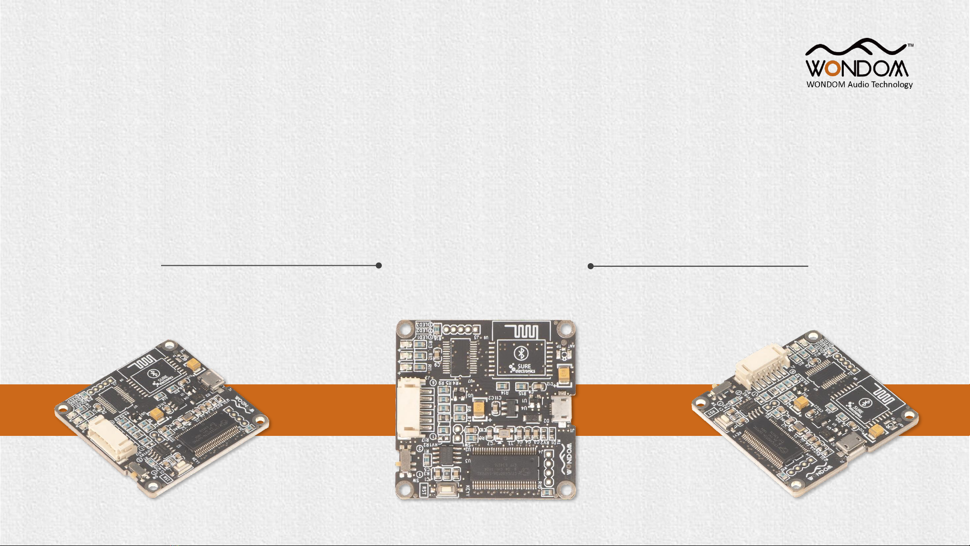
IN-CIRCUIT PROGRAMMER FOR ADAU1701 DIGITAL SIGNAL - ICP1
By Sure Electronics Co., Ltd.

WONDOM ICP1 is an in-circuit programmer for customer programming of WONDOM products.
On-board self-boot EEPROM is included in ICP1 for operating the board independently of the Analog Devices, Inc.,
SigmaStudio™ software.
The package includes:
✓IN-CIRCUIT PROGRAMMER FOR ADAU1701 DIGITAL SIGNAL - ICP1 x 1
✓6-pin cable x 1
Overview
Functions Required Tools Applicable Products
Programming Analog Devices, Inc., SigmaStudio™JAB3
APM2

Product List
Model SKU Description Basic Cables Included
ICP1 DB-DP11219 In-circuit Programmer for ADAU1701 Digital Signal 6Pin cable x 1
ICP3 DB-DP11224 WONDOM In-circuit Programmer with BLE Bluetooth for APP control 6Pin cable x 1
ICP5 DB-DP11226 In-circuit Programmer with UART for PC UI Control & BLE for APP
Control 6Pin cable x 1
APM2 AA-AP23122 ADAU1701 Audio Digital Signal Processor Kernel Board -
APM3 AA-AA11428 ADAU1701 Audio Digital Signal Processor Interface Extension Kit 10Pin cable x 1
JAB3-1100 AA-JA31181 1x 100 Watt Class D Audio Amplifier Board with Audio DSP - JAB3-1100
Power cable x 1
Speaker cable x 1
3.5mm AUX IN cable x 1
JAB3-160 AA-JA31211 1 x 60 Watt Class D Audio Amplifier Board with Audio DSP - JAB3-160
JAB3-250 AA-JA32172 2 x 50 Watt Class D Audio Amplifier Board with Audio DSP - JAB3-250
JAB3-230 AA-JA32473 2 x 30 Watt Class D Audio Amplifier Board with Audio DSP - JAB3-230
Notes:
- Represents no basic cable

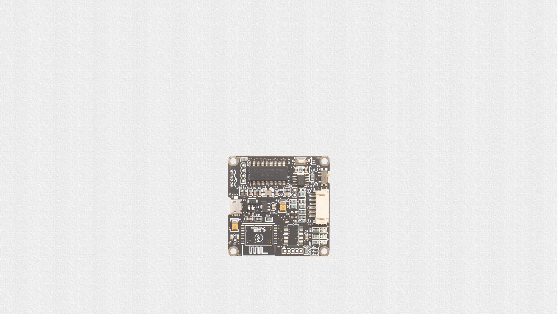
Interface Definition
In this document, we will mainly give instructions on the following applications:
1) How to achieve programming of APM2 / JAB3 with WONDOM ICP1
2) How to realize APP control of APM2 / JAB3 with WONDOM ICP1
Micro USB Port
1) DC5V power supply
2) Communication with computer
SW
When programming, please make sure
SW at ①(PROGRAM)
Programming Port
For connection with applicable
products with a 6-pin cable
KEY1
Reset

Open Source Files
for PROGRAMMING
Products Function File Version Download
APM2 Demonstration of Signal Flow Chart APM2_SigmaStudio.dspproj - Download
JAB3 - Mono Demonstration of Signal Flow Chart JAB3_SigmaStudio_MONO.dspproj - Download
JAB3 - Stereo Demonstration of Signal Flow Chart JAB3_SigmaStudio_STEREO.dspproj - Download
Note: All the "Demonstration of Signal Flow Chart" files are just for signal flow chart demonstration and customers can not u
se them as running programming.
How to achieve programming of APM2/JAB3
with WONDOM ICP1?
ICP1
IN-CIRCUIT PROGRAMMER FOR ADAU1701
DIGITAL SIGNAL - ICP1
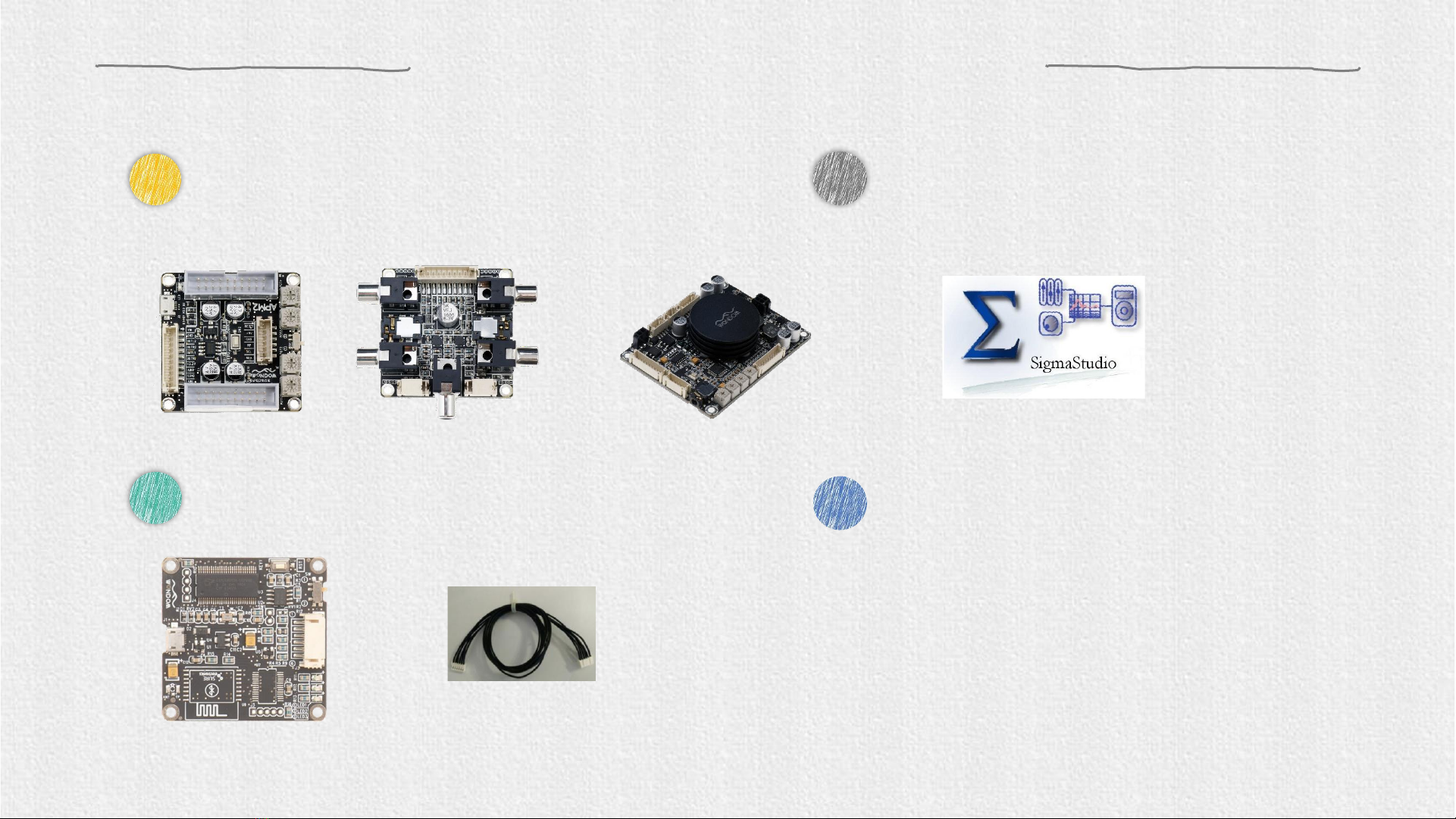
Before starting, please make sure you have the following items on hand.
Checklist
1WONDOM APM2+Extension Kit (APM3)/JAB3
2WONDOM ICP1 with a 6-pin cable
3Analog Devices, Inc. SigmaStudio™
4Accessories
Speakers
Cables
Phone
…
OR
+
To quickly get started with the programming of WONDOM
APM2 or JAB3 via ICP1, do the following steps:
1) Install the SigmaStuido software
2) Connect ICP1to computer
3) Connect audio cables of APM2/JAB3
4) Power up the audio system
5) Connect ICP1 with APM2/JAB3
6) Program
Quick Start
Click HERE to watch video.
Since the most steps of programming APM2 and JAB3 are the same, we will take APM2 as an example to
show you how to operate. If there is difference or points to note, we wil mark out with red words.
INSTALLING SIGMASTUDIO SOFTWARE CONNECTING THE AUDIO CABLES
1 3 42
SETTING UP THE ICP1
POWERING UP THE BOARD
CONNECTING ICP1 WITH APM2 / JAB3
How to program
5
PROGRAMMING
Be sure to follow these connection steps.

Download the installation package for SigmaStudio software in the
Analog.com. Download address is as follows. Click the EXE file and
finish installation according to the prompts.
https://www.analog.com/en/design-center/evaluation-hardware-and-
software/software/ss_sigst_02.html#software-overview
Installing Sigmastudio
software
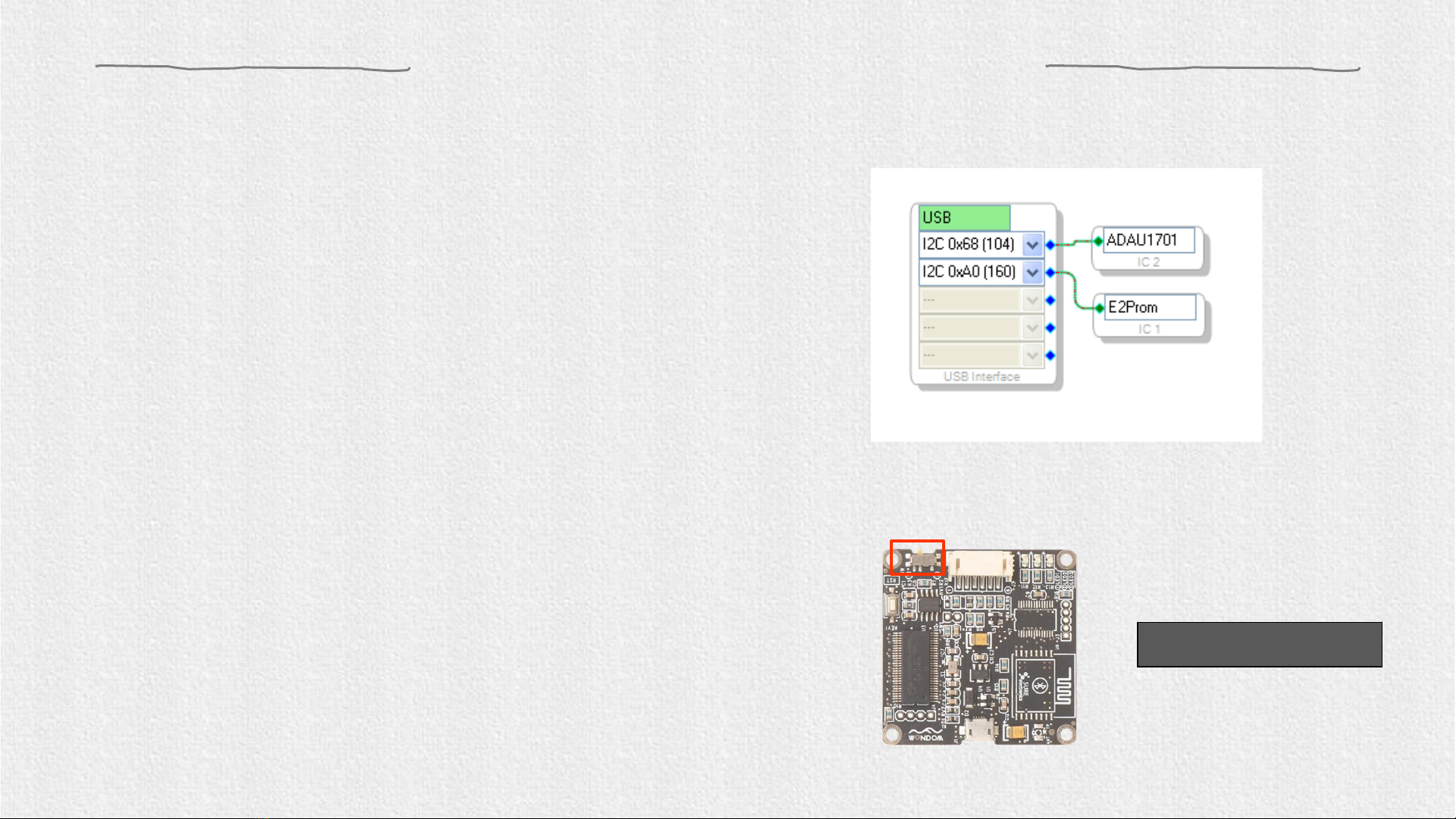
2. Set the SW of ICP1 at (PROGRAM)* and connect
the ICP1 to the computer with a USB cable.
1. Compile the needed program in advance.
Setting up the hardware
Figure 1
SW
4. Please note whether the ICP1 can be recognized by the
computer, if the underpainting of the “USB” turn green, it
represents the ICP1 is recognized, otherwise it will ture
orrange and you should reconnect the ICP1 until it turn
green. See figure 1.
3. Select “USBi” from the list on the left and drag it to
the blank area on the right. Repeat the action to
move “ADAU1701” and “E2Prom” to the right.
Do not connect ICP1 with target products (APM2/JAB3) now.
PROGRAM
SW Setting

01.
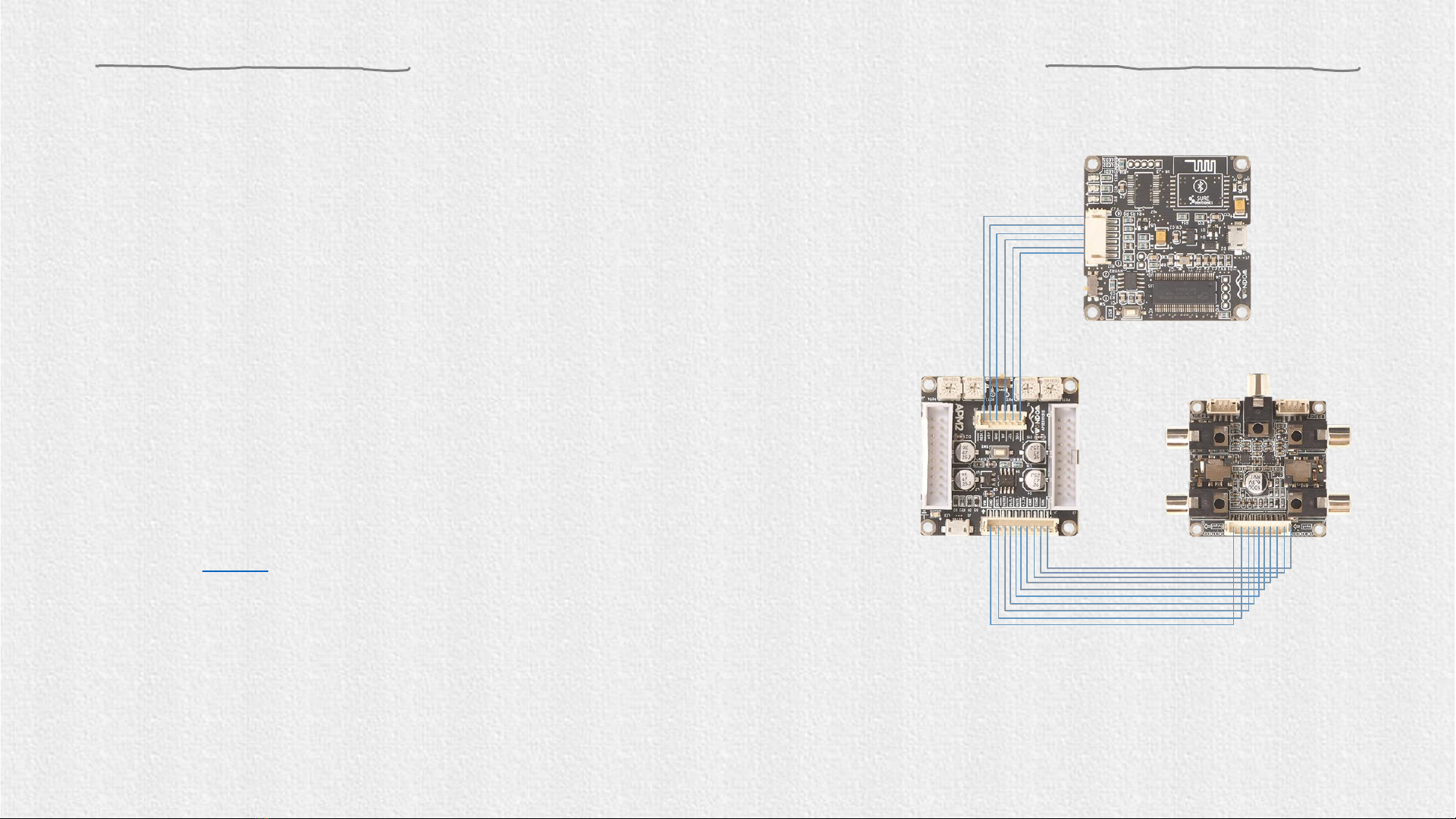
Connection
02.
Input
03.
Output
Connecting Audio Cables
Use the 10 pin to 10 pin cornoid
to connect APM2 with interface
extension kit (APM3) for playing
music.
This interface extension kit
(APM3) provides three methods
of audio input:
✓RCA
✓3.5mm Aux
✓PH-4PIN-2MM
This interface extension kit
(APM3) provides three channels
of audio output:
✓RCA
✓3.5mm Headphone
✓PH-4PIN-2MM
RCA 3.5mm Aux PH-4PIN-
2MM
RCA 3.5mm
Headphone PH-4PIN-
2MM

Powering up the board
1. Power of APM2:
The DSP Kernel Board (APM2) could be powered by:
1) 5V micro USB through micro USB charging port (J2)
2) External 5-12V DC Supply through Vin control port (J3/J4)
3) External 3.3V DC Supply through +3.3V control port (J3/J4)
2. Power of Extension Kit:
The Extension Kit (APM3) is powered by the Kernel Board (APM2)
3. Power of IC Programmer:
WONDOM IC Programmer could be powered by:
1) 5V micro USB through micro USB charging port (J1)
2) External 5V DC Supply from DSP Kernel Board (APM2)
Power up the APM2.
Make sure the SW1 of APM2 is set at ①(RUN). (Skip this step when programming JAB3)
Connect ICP1 with APM3 through 6-pin cable.
Input audio signal to JAB3 and make sure the two LEDs on JAB3 are on before connecting ICP1 with JAB3. Skip this step when
programming APM2.

Programming
2.Click the “Link Compile Download” (see figure 3) and
you will find “Active:Compiled” in the lower right
corner of your computer.
3. Make sure the SW of ICP1 is at (PROGRAM) and the SW1 of APM2 is at (RUN), and right-click the “ADAU1701”
and select “Write Latest Compilation to E2PBOM” to download the program (see figure 4), then you will see a window,
choose the “I2C” on the right and click “OK” (see figure 5).
Figure 4
Figure 5
Figure 3
1.Click the “Link Compile Connect” (see figure 2)
and you will find “Ready:Compiled” in the
lower right corner of your computer.
Figure 2
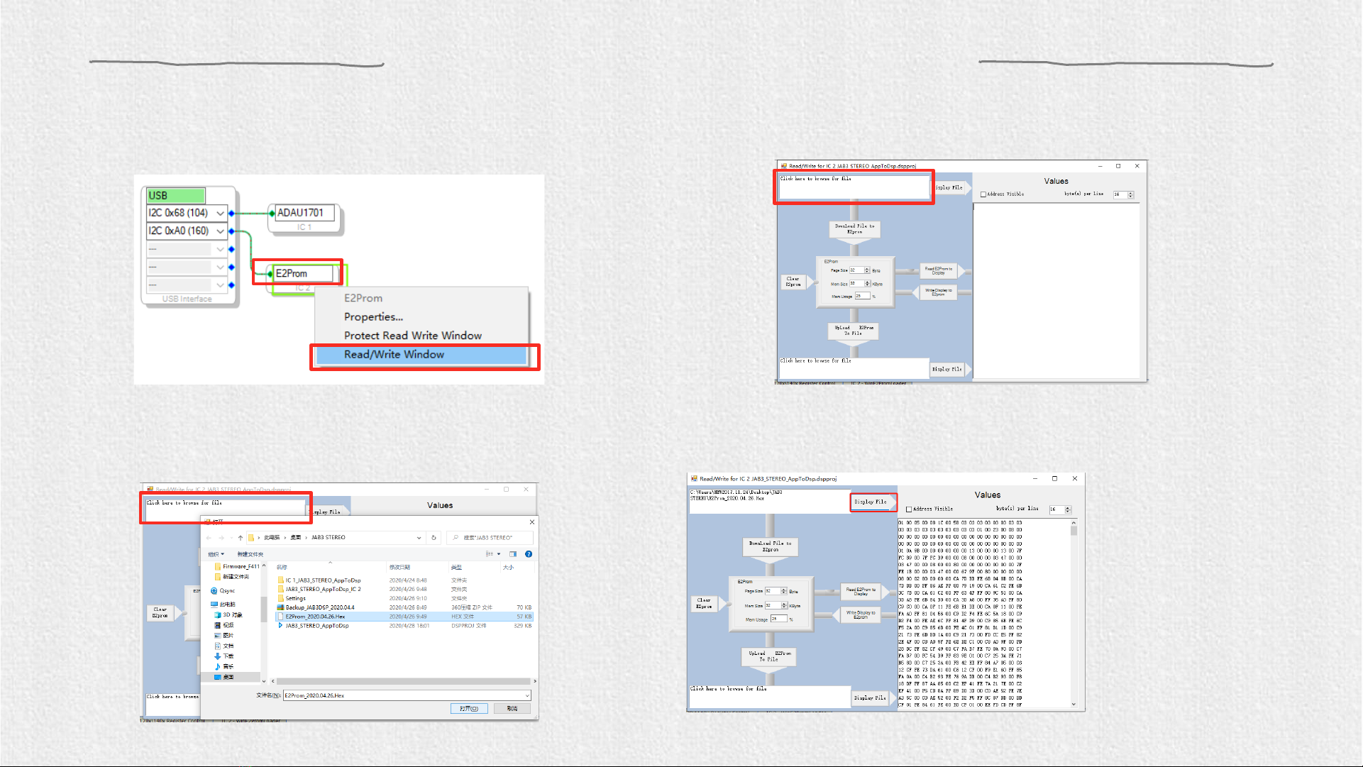
Original Firmware Restore
1. Right click the “E2Prom” (see Figure 6) and click ‘Read/Write Window’. You will see the following interface (Figure 7).
Figure 6 Figure 7
2. Click ‘Click here to browse for file’ and select firmware file (Figure 8). Then click ‘Display File’ like Figure 9.
Figure 8 Figure 9

Original Firmware Restore
3. Click ‘Write Display to E2prom’ then click ‘OK’ of the prompt box (Figure 10).
Figure 10

TROUBLE SHOOTING
TROUBLE HOW TO SOLVE
ICP1
cannot be recognized by PC
➢
Make sure the Micro USB cable is of good quality and supports data
communication
➢
Make sure ICP1 is not connected to controlled device (APM2) when
connected to PC
Cannot
writing the program into APM2 successfully
➢
Make sure the ICP1 be recognized by PC
➢
Make sure the SW of ICP1 is at (PROGRAM) and the SW1 on APM2
is set at (RUN)
Cannot
writing the program into JAB3 successfully
➢
Make sure JAB3 is given audio signal and the two LEDs are on
➢
Make sure the ICP1 be recognized by PC
➢
Make sure the SW of ICP1 is at (PROGRAM)
APM2 / JAB3 cannot
work normally (cannot play music) under powering
condition when connected with ICP1
➢
Make sure the connection steps are correct and check the
input/output cables
➢
Disconnect with ICP1 and re-power APM2
➢
Make sure the SW1 on APM2 is set at (RUN)
(Not applicable to JAB3)
Table of contents
Other Sure Electronics Motherboard manuals


