SPECIFICATIONS
Range:
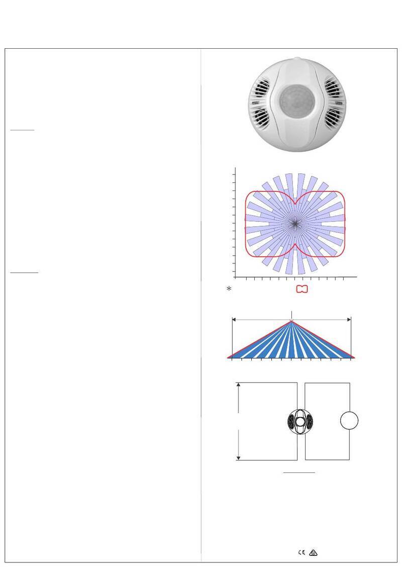
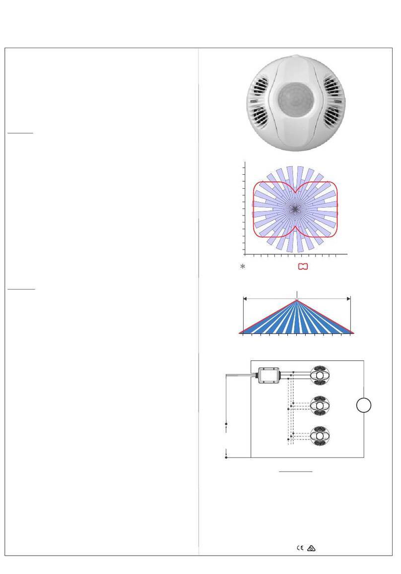
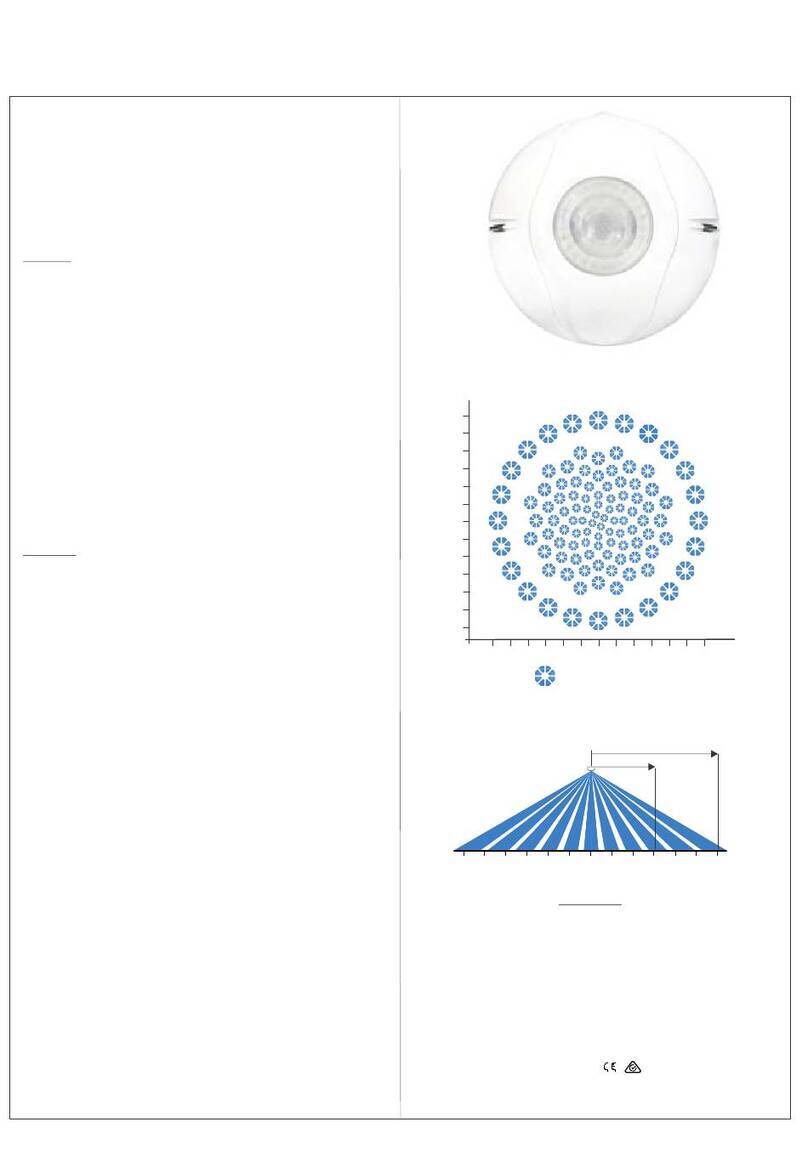
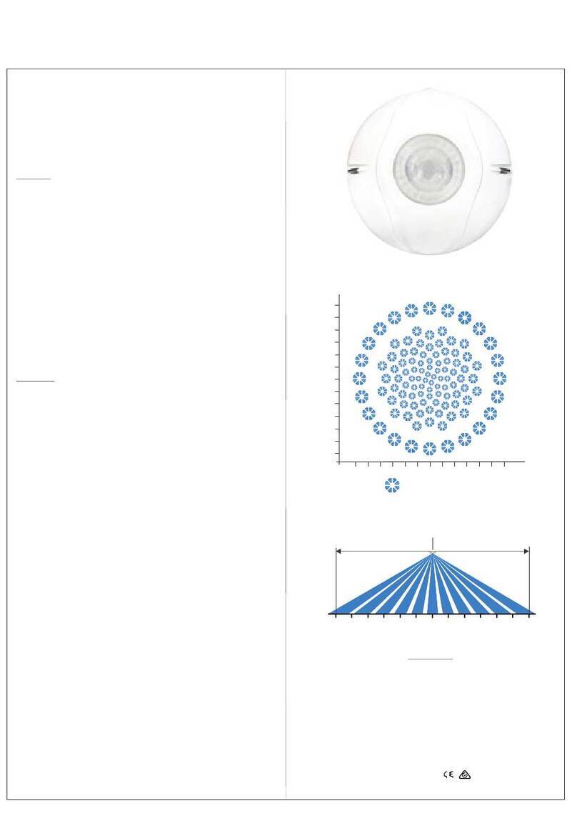
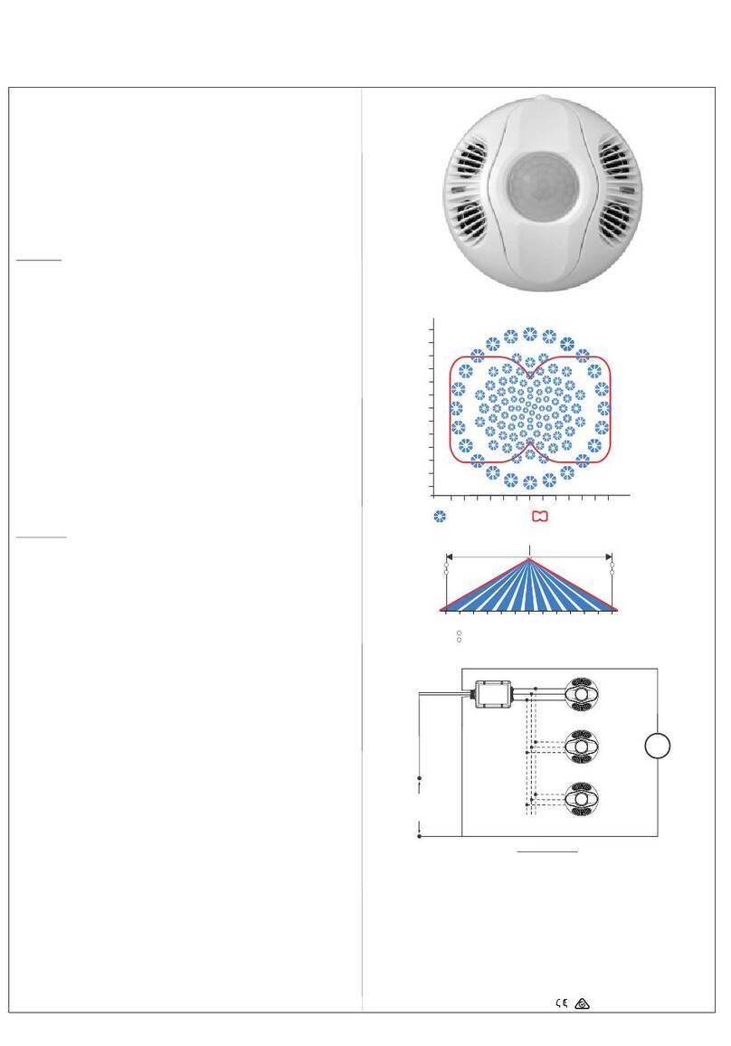
Sensor Optical View Pattern
Optical Fields-of-View:
Sensor Optical View Pattern
Depending on mounting height see below
(side view, in meters)
Long-range Mid-range Short-range Look-down
48 48 16 10
(top view, in meters, 2 mounting
height)
Note: Specifications are subject to change without notice.
; .
.4m
CS-106 PYROFLEX™ Motion Sensor
Operation and Specifications SUREN
©2009 SUREN Systems, Ltd.. All rights reserved. SUREN™, PYROFLEX™ are trademarks of SUREN. SUREN Part no.: N-ML01-0019-01-1 Rev 1.Printed in China
Tamper Switch:
IR Sensor:
Power Supply:
Relay:
Housing Material:
Dimensions:
Complies with:
( NC ) 50mA @ 30Vdc
PYROFLEX™, Dual elements
8-16 Vdc; 20 mA at 12 Vdc
Solid state, 60V, 150 mA,
1500 V isolation
High-impact ABS
Ф93 x 38 mm ( Dia x D )
CCC
rms
.
EN 50131-2-2 Grade 2, Class Ⅱ
Limitations of Sensor Products: Sensor products and associated systems do not offer guaranteed
performance in ordinary situations or in special situations including but not limited to burglary, fire, or other
emergencies. They may fail to function for diverse reasons, including (but not limited to): power failure, dead
batteries, improper installation, coverage “blind spots”, coverage areas overlooked during installation,
component failure, or inadequate maintenance. Sensors and their associated systems should be checked
weekly to ensure that all devices are working properly.
SUREN LIMITED WARRANTY
SUREN Systems, Ltd., of Fo Tan, Shatin, Hong Kong, warrants its products to be in conformance with its own
plans and specifications and to be free from defects in materials and workmanship under normal use and
service for twelve months from the date of original purchase. Seller's obligation shall be limited to repairing or
replacing, at its option, free of charge for materials or labor, any part which is proved not in compliance with
Seller's specifications or proves defective in materials or workmanship under normal use and service. Seller
shall have no obligation under this Limited Warranty or otherwise if the product is altered or improperly
repaired or serviced by anyone other than Seller. For warranty service, return transportation prepaid, to
SUREN Systems, Ltd., Unit 15, 12/F, Block B, Wah Sang Industrial Building, 14-18 Wong Chuk Yeung Street,
Fo Tan, Shatin, Hong Kong. Seller has no obligation to attend the buyer's location to retrieve the goods or
make repairs on site.
There are no warranties, expressed or implied, of merchantability, or fitness for a particular purpose or
otherwise, which extend beyond the description on the face hereof. In no case shall seller be liable to anyone
for any consequential or incidental damages for breach of this or any other warranty, express or implied, or
upon any other basis of liability whatsoever, even if the loss or damage is caused by its own negligence or
fault.
Seller does not represent that the products it sells may not be compromised or circumvented; that the
products will prevent any personal injury or property loss by burglary, robbery, fire or otherwise; or that the
products will in all cases provide adequate warning or protection. Customer understands that a properly
installed and maintained alarm system may only reduce the risk of a burglary, robbery, or fire without warning,
but it is not insurance or a guarantee that such will not occur or that there will be no personal injury or property
loss as a result.
Consequently, seller shall have no liability for any personal injury; property damage or other loss based on a
claim the product failed to give any warning. However, if seller is held liable, whether directly or indirectly, for
any loss or damage arising under this limited warranty or otherwise, regardless of cause or origin, seller's
maximum liability shall not in any case exceed the purchase price of the product, which shall be the complete
and exclusive remedy against seller.
This warranty replaces any previous warranties and is the only warranty made by Seller on this product. No
increase or alteration, written or verbal, of the obligations of this Limited Warranty is authorized.
w w w . s u r e n s y s . c o m
U.S. Patent NO: 7,042,134 7,141,910
U.K. Patent NO: GB 2 427 270 Patents pending worldwide.
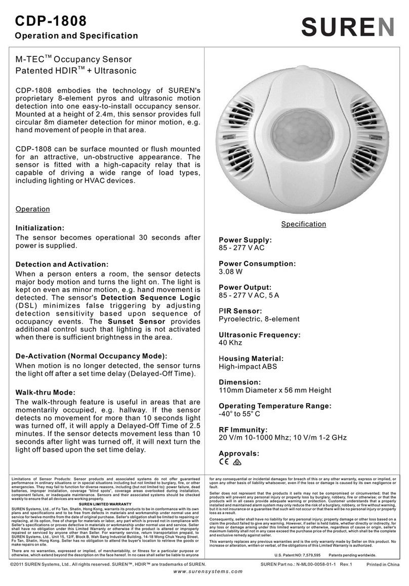
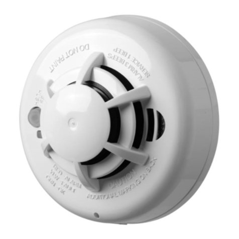
The CS-106 is a professional state-of-the art motion sensor engineered
with the world's best components and materials. Every aspect of this sensor
provides the most reliable motion sensing with freedom from false alarms.
Microcomputer-based SureSpot™ processing assures the best possible
intruder detection with superior false alarm rejection. In addition, patented
PYROFLEX™ IR detection provides much stronger intrusion signals than
conventional detectors the microcomputer easily tells real intrusions from
false alarms. Bi-directional temperature compensation supports the
best possible detection throughout the wide operating temperature
range
Following power-on, a CS-106 sensor is fully operational after a two-minute
warm-up. During warm-up, its LED is ON. After warm-up, the sensor starts a
ten-minute walk-test mode.
The CS-106 should be tested once per year.
Enable the LED (JP1 ON). (See page 2 step 8).
If the LED is not enabled, then, without removing power, set JP1 to ON. Walk
across the monitored area (within the sensor's optical fields-of-view). With
sensitivity set at STANDARD, the LED should turn ON (for Alarm) after about
two to four normal steps. With the sensitivity set at HIGH, the LED should
turn ON (for Alarm) after about one to three normal steps. Each time the LED
turns ON, wait for it to turn OFF. Then, wait 12 seconds before continuing the
walk-test. When there is no motion in the monitored area, the LED should
remain OFF.
Cycle power-off/power-on, then Walk-test immediately
after warm-up with one of the 10-minute walk-test modes.
Immediately after completion of warm-up, the sensor starts one of two types
of ten-minute walk-test mode, according to the position of JP2. (See page 2
step 8 for sensitivity setting.)
With the sensor sensitivity set at STANDARD, the
sensor LED flashes , until an Alarm occurs (upon the third flash for nominal
signals; upon the second flash for strong signals). When an Alarm occurs,
the LED stays ON for five seconds (while the Alarm relay is open).
With sensitivity set at HIGH, the sensor LED flashes
each time a person enters or leaves one of the sensor's optical fields-of-view
(FOV). In this mode, the LED does not indicate Alarm state, though the Alarm
works normally.
The LED flash indicates an event generally when a person enters or
leaves one of the sensor fields-of-view.
After the end of the ten-minute walk-test mode, the LED operates as
selected by the LED enable switch JP1.
Dual-element detector fields-of-view alternate between (+) and (-) polarity.
SureSpot™-qualified signal events are counted as “pulses” when polarity
alternates. Depending on sensitivity setting, (+,-), (-,+), (+,-,+) or (-,+,-) will
cause an alarm.
CS-106 supervision functions include these tests:
Ambient temperature in-range;
Detector electronics okay.
When a failure is detected, then:
1) the LED blinks ON/OFF every second;
2) Alarm relay will not re-close after an alarm signal event.
: The sensor will NOT initiate an alarm upon failure.
If the sensor’s optics/cover is rotated toward its removal position or if
it is removed then tamper switch opens
.
SENSOR INITIALIZATION
WALK TEST
10-MINUTE WALK-TEST MODES
ALARM PROCESSING
SUPERVISION
TAMPER SWITCH
Note:
In Normal Operating Mode:
In Special Modes:
Flash Counting Mode:
*
View Finder Mode: *
* “ ” -
NOTE
,
, .
RF Immunity:
White Light Immunity:
Sensitivity:
Operating Temperature
Range:
Accessories:
Temperature Compensation:
20 V/m 10-1000 MHz;
10 V/m 1-2 Ghz
6500 lux
Selectable: 2-event or 3-event
-40°C to +55° C
Trim ring for solid ceiling
Retaining spring for drop ceiling
Bi-directional
;
( )
R2 2
.
( )R4 0.
( )
R3 0
.
( )
R1 0
.
( )
R1 5
.
( )2 4.
(0 8).
(1 5).
(4 0).
( )3 0.
(2 2).
(1 0).
(.)3 7
(6 1).
(4 6).
(3 4).
(2 3).
(1 5).
(0 3).
(0 8).


