SUREN M-TEC CDP-808 User manual

CDP-808
Operation and Specification SUREN
©2011 SUREN Systems, Ltd.. All rights reserved. SUREN™, HDIR™ are trademarks of SUREN. SUREN Part no.: N-ML00-0058-01-1 Rev.1 Printed in China
Limitations of Sensor Products: Sensor products and associated systems do not offer guaranteed
performance in ordinary situations or in special situations including but not limited to burglary, fire, or other
emergencies. They may fail to function for diverse reasons, including (but not limited to): power failure, dead
batteries, improper installation, coverage “blind spots”, coverage areas overlooked during installation,
component failure, or inadequate maintenance. Sensors and their associated systems should be checked
weekly to ensure that all devices are working properly.
SUREN LIMITED WARRANTY
SUREN Systems, Ltd., of Fo Tan, Shatin, Hong Kong, warrants its products to be in conformance with its own
plans and specifications and to be free from defects in materials and workmanship under normal use and
service for twelve months from the date of original purchase. Seller's obligation shall be limited to repairing or
replacing, at its option, free of charge for materials or labor, any part which is proved not in compliance with
Seller's specifications or proves defective in materials or workmanship under normal use and service. Seller
shall have no obligation under this Limited Warranty or otherwise if the product is altered or improperly
repaired or serviced by anyone other than Seller. For warranty service, return transportation prepaid, to
SUREN Systems, Ltd., Unit 15, 12/F, Block B, Wah Sang Industrial Building, 14-18 Wong Chuk Yeung Street,
Fo Tan, Shatin, Hong Kong. Seller has no obligation to attend the buyer's location to retrieve the goods or
make repairs on site.
There are no warranties, expressed or implied, of merchantability, or fitness for a particular purpose or
otherwise, which extend beyond the description on the face hereof. In no case shall seller be liable to anyone
for any consequential or incidental damages for breach of this or any other warranty, express or implied, or
upon any other basis of liability whatsoever, even if the loss or damage is caused by its own negligence or
fault.
Seller does not represent that the products it sells may not be compromised or circumvented; that the
products will prevent any personal injury or property loss by burglary, robbery, fire or otherwise; or that the
products will in all cases provide adequate warning or protection. Customer understands that a properly
installed and maintained alarm system may only reduce the risk of a burglary, robbery, or fire without warning,
but it is not insurance or a guarantee that such will not occur or that there will be no personal injury or property
loss as a result.
Consequently, seller shall have no liability for any personal injury; property damage or other loss based on a
claim the product failed to give any warning. However, if seller is held liable, whether directly or indirectly, for
any loss or damage arising under this limited warranty or otherwise, regardless of cause or origin, seller's
maximum liability shall not in any case exceed the purchase price of the product, which shall be the complete
and exclusive remedy against seller.
This warranty replaces any previous warranties and is the only warranty made by Seller on this product. No
increase or alteration, written or verbal, of the obligations of this Limited Warranty is authorized.
w w w. s u r e n s y s t e m s . c o m
U.S. Patent NO: 7,579,595 Patents pending worldwide.
TM
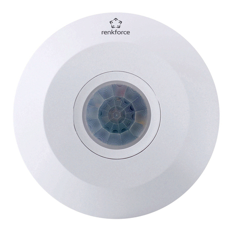
M-TEC Occupancy Sensor
TM
Patented HDIR + Ultrasonic
CDP-808 embodies the technology of SUREN's
proprietary 8-element pyros and ultrasonic motion
detection into one easy-to-install occupancy sensor.
Mounted at a height of 2.4m, this sensor provides full
circular 8m diameter detection for minor motion, e.g.
hand movement of people in that area.
CDP-808 can be surface mounted or flush mounted
for an attractive, un-obstructive appearance. One or
many sensors can be connected with Suren's (or
compatible) power packs to control a wide range of
load types, including lighting or HVAC devices.
Operation
Initialization:
The sensor becomes operational 30 seconds after
power is supplied.
Detection and Activation:
When a person enters a room, the sensor detects
major body motion and turns the light on. The light is
kept on even as minor motion, e.g. hand movement is
detected. The sensor's Detection Sequence Logic
(DSL) minimi zes f alse trig gering by a djusting
detection sensitivity based upon seq uen ce of
occupancy events. The Sunset Sensor provides
additional control such that lighting is not activated
when there is sufficient brightness in the area.
De-Activation (Normal Occupancy Mode):
When motion is no longer detected, the sensor turns
the light off after a set time delay (Delayed-Off Time).
Walk-thru Mode:
The walk-through feature is useful in areas that are
momentarily occupied, e.g. hallway. If the sensor
detects no movement for more than 10 seconds light
was turned off, it will apply a Delayed-Off Time of 2.5
minutes. If the sensor detects movement less than 10
seconds after light was turned off, it will next turn the
light off based upon the set time delay.
Specification
Power Supply:
24 V DC (Power pack PS-124 or PS-224 required)
Power Consumption:
0.86 W
Control Signal Output:
24 V DC, 15 mA
PIR Sensor:
Pyroelectric,8-element
Ultrasonic Frequency:
40 Khz
Housing Material:
High-impact ABS
Dimension:
110mm Diameter x 56 mm Height
Operating Temperature Range:
o o
-40 to 55 C
RF Immunity:
20 V/m 10-1000 Mhz; 10 V/m 1-2 GHz
Approvals:

CDP-808
Installation SUREN
©2011 SUREN Systems, Ltd.. All rights reserved. SUREN™, HDIR™ are trademarks of SUREN. SUREN Part no.: N-ML00-0058-01-1 Rev.1 Printed in China
w w w. s u r e n s y s t e m s . c o m
Wiring Diagram:
Detection range
at 2.4m height
Detection Area:
0
m
m
m
2
2
2
2
0
0
4
4
4
2
2
4
4
4
Top view
Side view
Accessories:
·Brackets, screws and wall plugs for surface mount
in solid ceiling
·Spring clips for flush mount in drop ceiling
·Infra red zone mask
Location:
·Determine the number of sensors required to cover
the floor area
·Install the sensor near work area where walk-path
cuts across radial lines, not towards the sensor
·Do not install the sensor near ventilation outlet
·Avoid facing the ultrasonic transceivers to each
other to minimize interference
Procedure:
·Prepare sensor mount. See illustration in the next
page
·Connect the sensor as shown in the wiring diagram.
Make sure power supply is turned off
·Make sure there are no wiring exposed before
mounting the sensor
·Mount the sensor and turn on the power supply
·Open the cover, review settings and change if
necessary. See Settings section
·Initiate test mode, replace the cover and conduct
walk-test
Walk-Test:
·Toggle dip switch B3 (Off-On-Off) to enter test
mode. If B3 is already in the On position, moving it
to the Off position will also activate test mode
·Amber LED will flash once every second when the
sensor is in test mode
·During this time, the sensor will turn the light off
after 5 seconds if there are no movement
·Test movement at entry point, walk path and
occupancy area
· Sensor will exit test mode after 15 minutes
LED Indicator:
· LED indicator can be enabled or disabled by dip
switch B2
·Recommended for troubleshooting
·Red LED indicates motion detected by infra red
sensor
·Green LED indicates motion detected by ultrasonic
sensor
PIR Optical View Pattern Ultrasonic Detection Pattern
PIR detection of minor motion, e.g. hand movement
Ultrasonic detection of body motion
1
2
11
22
Light
Live
Neutral
+
+
+
Line
85 - 277 V AC
50/60Hz
Load
-
-
-
Control
Control
Control
Sensor 1
Sensor 2
....
Sensor N
Power
Pack
Note: more than one sensor can be connected
to a power pack.

Best Detection Areae
a
Best Det
e
c
t
i
o
n
A
r
S
I
D
E
V
I
E
W
T O P VIEW
8
0
C
M
Drop-Ceiling Mounting: Base Preparation
Install the two retaining springs as shown.
Drop-Ceiling Mounting: Panel Preparation
Use a hole saw to cut a 85 mm circular hole in the
drop-ceiling panel at the desired location.
Drop-Ceiling Mounting: Sensor Installation
Press the retaining springs together, then push
the springs and the sensor base through the hole
until the sensor rim is seated against the panel.
Sensor Opening
Slide a fingertip under the tab at one end of the
cover. Pull gently to remove the cover.
Solid-Ceiling Mounting
Use the three screws (supplied with the sensor)
to fasten the base ring to the ceiling. Align the
sensor's two eyelets with the base ring's two
hooks. Press the sensor onto the base ring.
Sensor Mounting Choices
The sensor may be mounted either in a drop-
ceiling panel, or on a solid ceiling. In a drop-
ceiling panel, two metal springs serve to retain
the sensor in the panel. On a solid ceiling, the
sensor is mounted on a base ring (supplied with
the sensor).The base ring is fastened to the
ceiling by means of three screws.
5
8
2
11
Delayed-Off Time Adjustment
The sensor turns light off if motion is not detected
within the Delayed-Off Time interval. For less
disruption, adjust clockwise (CW). For better
energy savings, adjust counter-clockwise (CCW).
Sets the infrared range
Range setting
Full CCW = min.
Full CW = max.
Sets the ultrasonic range
Range setting
Full CCW = min.
Full CW = max.
Operation Control Console
All aspects of sensor operation can be adjusted
here.
Ambient Light
20Lux 40Lux 80Lux 160Lux 320Lux
Delayed-Off Time
30sec 5min 10min 20min 30min
Note: The mounting clips indicated by the arrows
represent the direction of the longer ultrasonic
range shown in the Detection Area diagram.
Sunset Sensor Adjustment
The sunset sensor saves energy by not switching
the light on when there is sufficient daylight in the
room. It can be enabled or disabled by the dip
switch B1. When the sunset sensor is enabled, the
sensor goes into stand-by mode when the natural
light level exceeds the selected Lux level
inhibiting the light from turning on. To set the Lux
level, draw curtains or shades until the room is at
the darkness that light should be turned on. Adjust
the Lux level from low to high until lighting is
activated. Note that the sunset sensor is disabled
when the occupancy sensor is in test mode.
Ultrasonic Adjustment
For maximum range and sensitivity, set fully
clockwise (CW). If reduced range and sensitivity
are required, then turn counter-clockwise (CCW)
and test.
Infrared Adjustment
For maximum range and sensitivity, set fully
clockwise (CW). If reduced range and sensitivity
are required, then turn counter-clockwise (CCW)
and test.
Dip Switch Settings
Off On
A1 Multi/Single Technology
A2 Technology Activated
A3 Not Used
A4 Walk-Thru/Normal Walk-Thru Enabled Normal Occupancy
B1 Sunset Sensor Enabled Disabled
B2 LED Indicator Enabled Disabled
B3 Test Mode
B4 Not Used
Off-On-Off / On-Off
Bank A
Bank B
Dip
Switch Function
Settings
Features enabled by the combination of
A1 & A2 are shown in the table below.
A1 A2 Feature
Off Off
PIR technology turns light on; however, motion detection by
either technology will keep the light on. If neither technology
detects motion, the light turns off after the Delayed-Off time.
[Choose this option to reduce false activation due to ultrasonic
technology.]
Off On
PIR or Ultrasonic technology turns light on and keeps light on.
If neither technology detects motion, the light turns off after the
Delayed-Off time. [Default]
On Off Only PIR technology is active.
On On Only Ultrasonic technology is active.
Other SUREN Security Sensor manuals
SUREN
SUREN CPL-1312 User manual
SUREN
SUREN CDL-1608 User manual

SUREN
SUREN CDL-608 User manual
SUREN
SUREN CDL-608R12 User manual
SUREN
SUREN CDL-608C24 Instruction Manual
SUREN
SUREN M-TEC CDP-808C24 User manual
SUREN
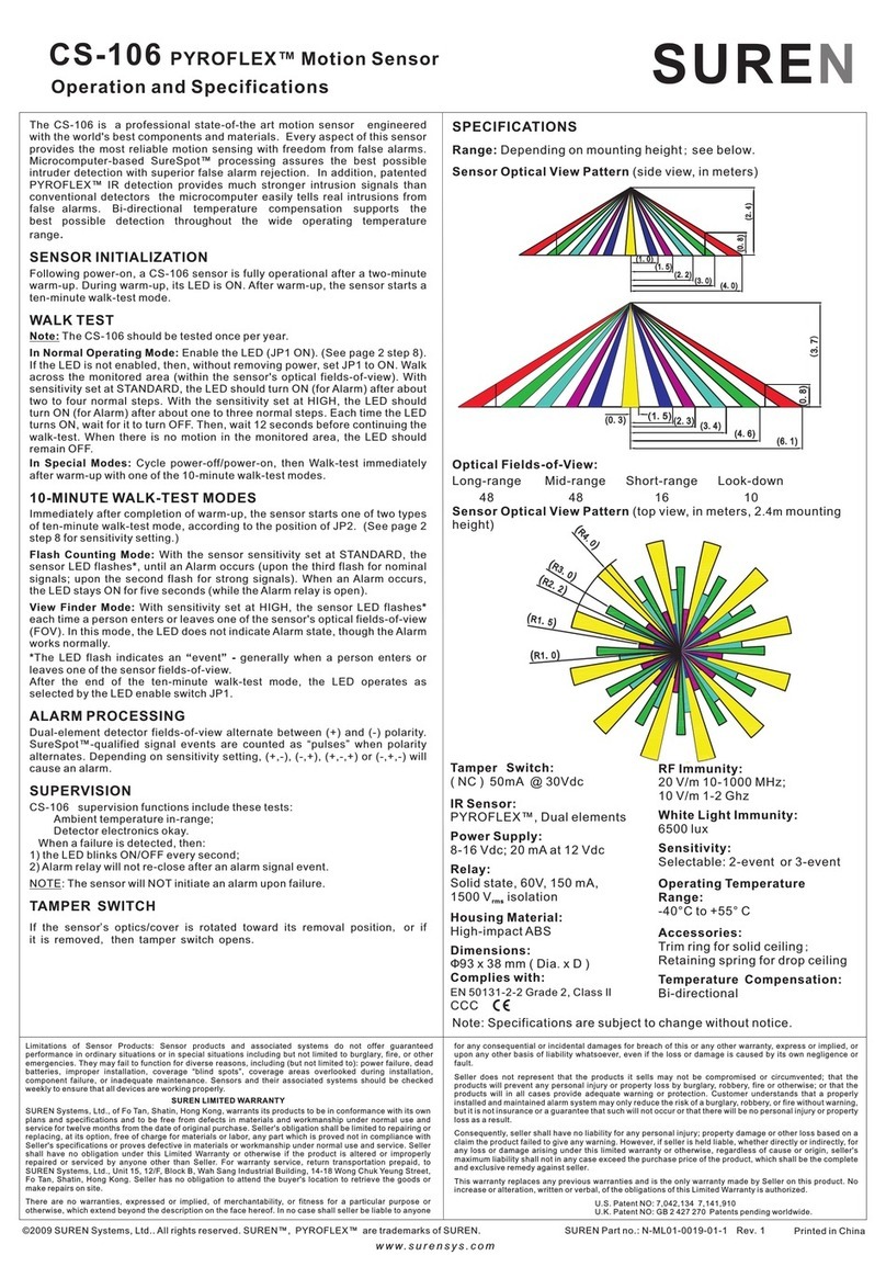
SUREN PYROFLEX CS-106 User manual
SUREN
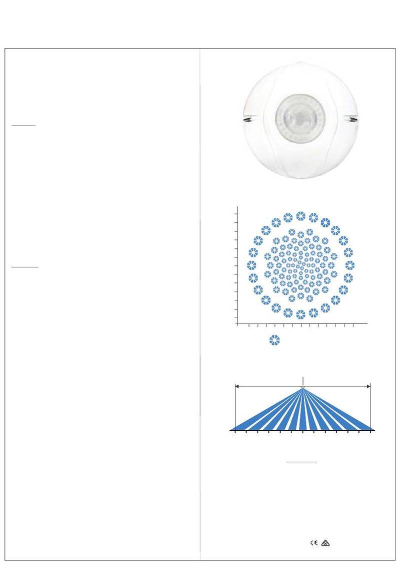
SUREN HB-1316 User manual
SUREN
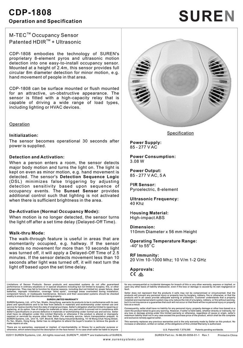
SUREN M-TEC CDP-1808 User manual
Popular Security Sensor manuals by other brands
Bosch
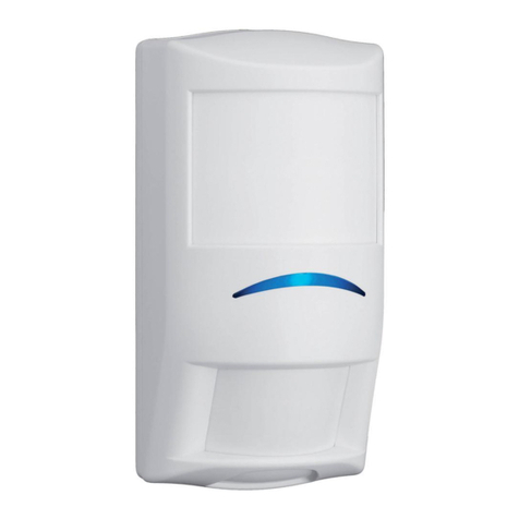
Bosch TriTech+ ISC-PDL1-WA18G installation instructions
Trotec
Trotec LD6000 operating manual
Johnson Controls
Johnson Controls Tyco SR Series Quick start and installation guide
Visonic
Visonic NEXT K9-85 installation instructions
Linear
Linear NAPPIR01 installation instructions
MSA
MSA Ultra Elite-H operating manual

