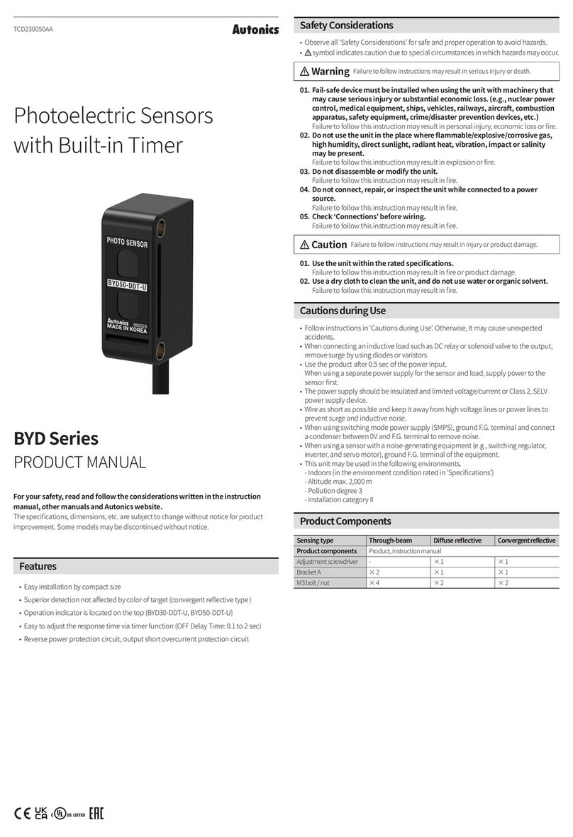
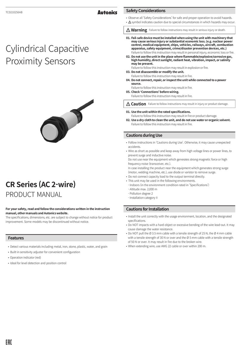
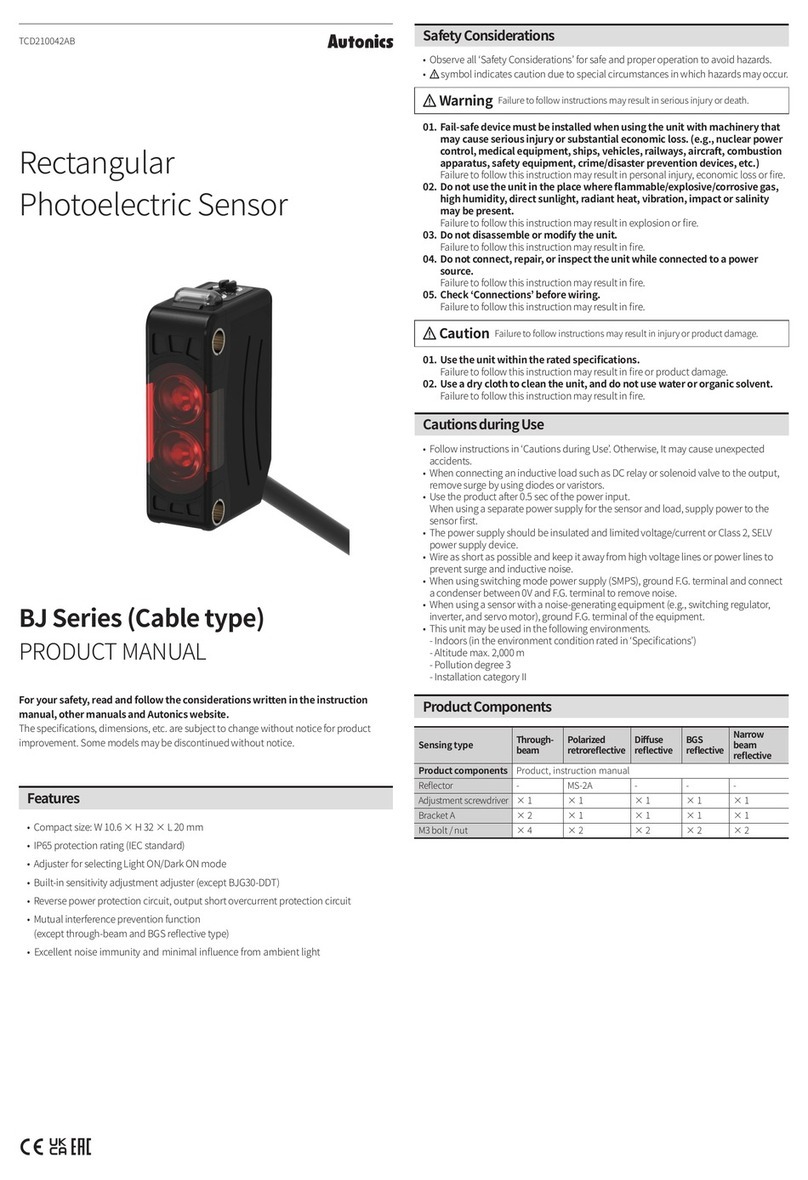
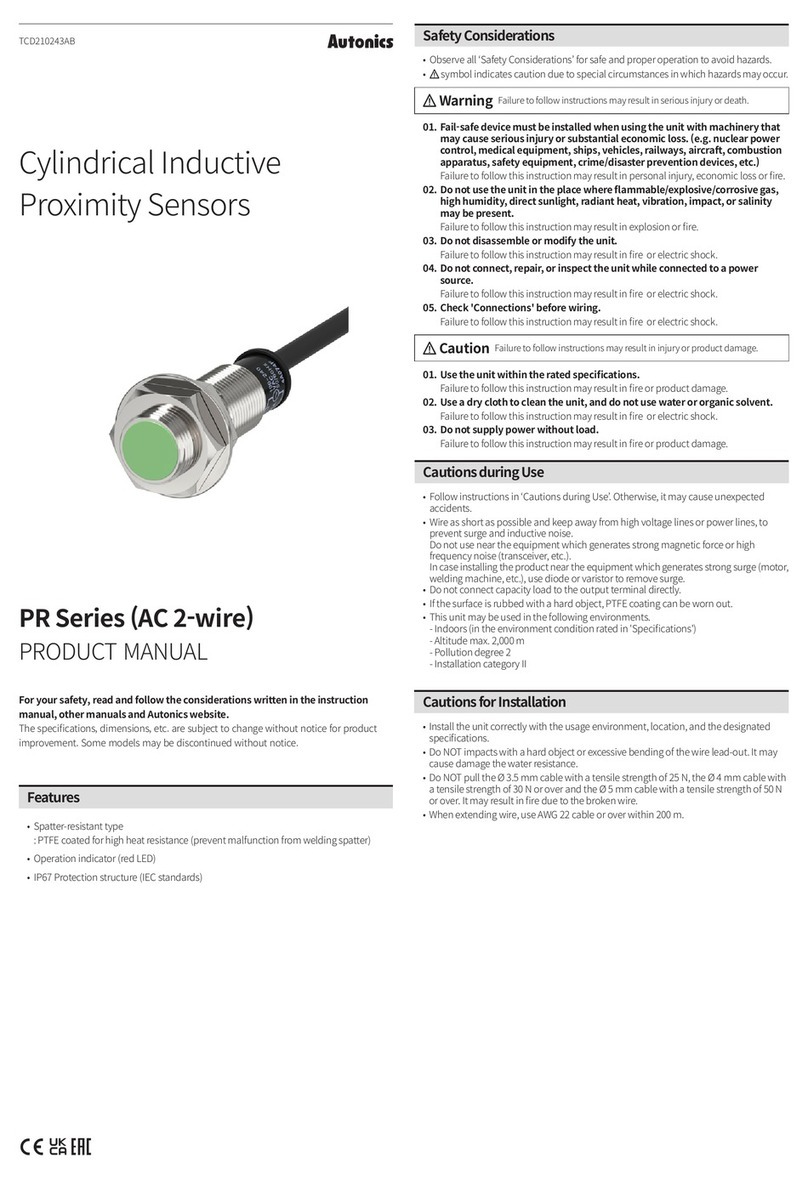
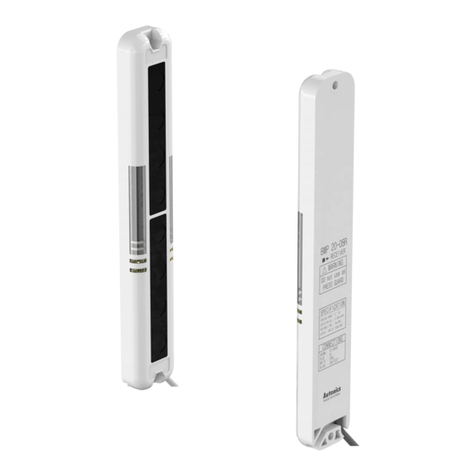
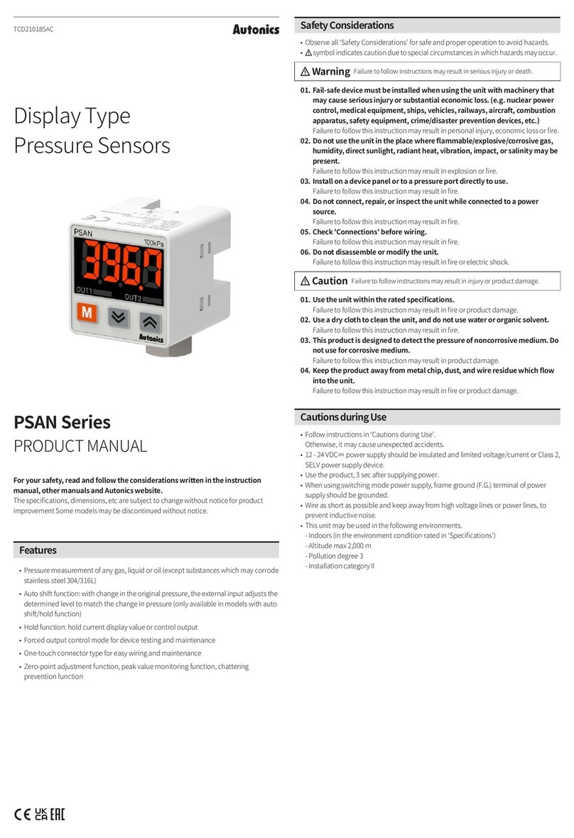
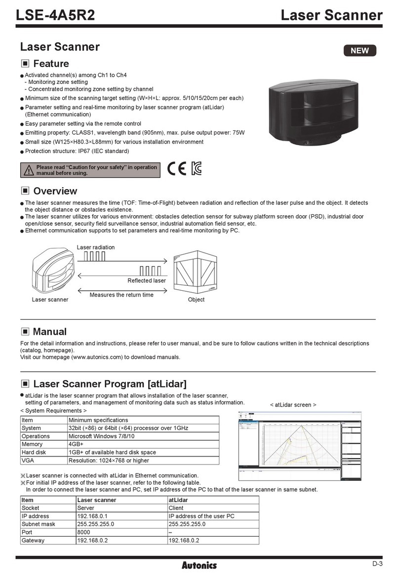
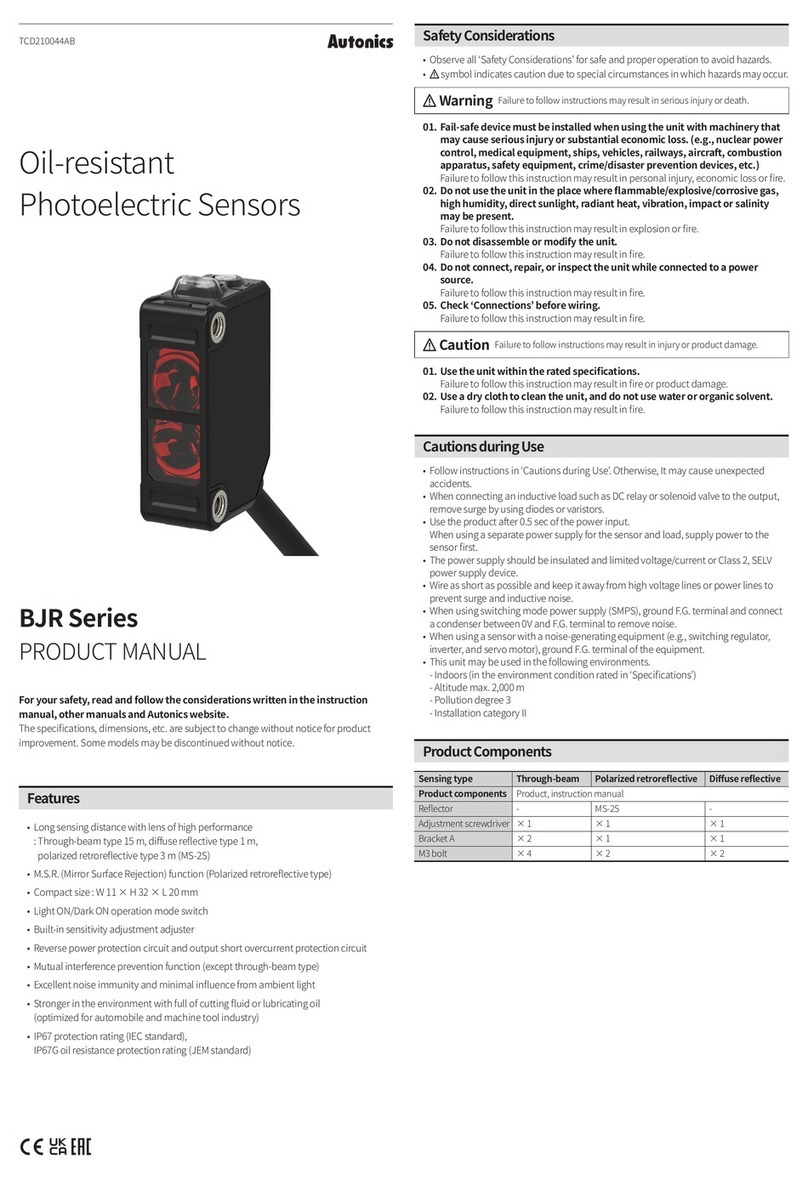
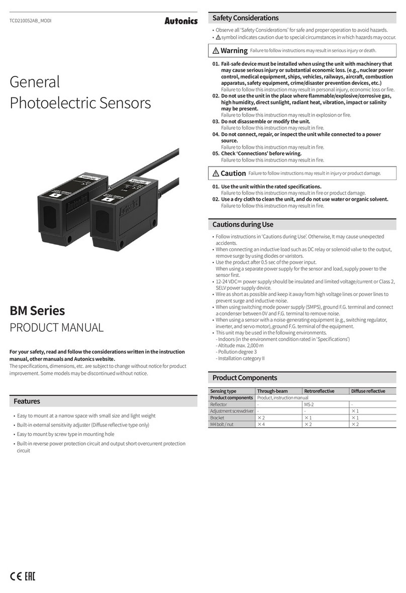
Autonics BW Series User manual

-|Transparent Guide|-
TCD210006AC
BW Series
For your safety, read and follow the considerations written in the instruction
manual, other manuals and Autonics website.
Features
Safety Considerations
Warning
01. Fail-safe device must be installed when using the unit with machinery that
may cause serious injury or substantial economic loss. (e.g. nuclear power
control, medical equipment, ships, vehicles, railways, aircraft, combustion
apparatus, safety equipment, crime/disaster prevention devices, etc.)
02. Do not use the unit in the place where ammable/explosive/corrosive gas,
high humidity, direct sunlight, radiant heat, vibration, impact, or salinity
may be present.
03. Do not connect, repair, or inspect the unit while connected to a power
source.
04. Check 'Connections' before wiring.
05. Do not disassemble or modify the unit.
06. This product is not safety sensor and does not observe any domestic nor
international safety standard.
Caution
01. Use the unit within the rated specications.
02. Use a dry cloth to clean the unit, and do not use water or organic solvent.
03. Do not use a load over the range of rated relay specication.
Cautions during Use

-|Transparent Guide|-
Operation Timing Chart
ON
OFF
ON
OFF
ON
OFF
ON
OFF
Stable light ON area
Unstable light OFF area
Unstable light ON area
Stable light OFF area
ON Level
OFF Level
Received
light
Connections
Brown White
Blue Black
■NPN open collector output ■PNP open collector output
Brown
Brown
White
White
Black
Black
Blue
Blue
+
1
2
3
1
2
3
OCP
SCP
EmitterReceiver
CIRCUIT CIRCUIT
Brown
Brown
White
White
Black
Black
Blue
Blue
1
2
3
1
2
3
+
EmitterReceiver
CIRCUIT CIRCUIT
OCP
SCP
Cautions during Installation
Sold Separately
Product Components
Ordering Information
BW ❶ - ❷ ❸
❶ Optical axis pitch
❷ Number of optical axes
❸ Control output
Operation Indicator
◑
●OFF ◑◑ / ◑◑◑
Item Emitter indicator Receiver indicator Control
output
Power ON
MASTER operation
SLAVE operation
TEST input
Break of emitter
Break of emitting element
OFF
Installation
mode
OFF
OFF
OFF
Stable light ON
Unstable light ON
Unstable light OFF OFF
Stable light OFF OFF
Break of receiver OFF
Control output
over current OFF
Malfunction of
Synchronous line OFF
Failure of emitter (time out)
OFF
Optical axis
misalignment alarm
Dimensions
•
Emitter Receiver
60
B
A
10
L
10
300
■ Optical axis Pitch (A, B)
20 mm
■ Optical axis Pitch (A, B)
40 mm
Model
Product
length
(L)
Num. of
optical
axes
Sensing
height
160
12
320 16
20
560
32
36
Model
Product
length
(L)
Num. of
optical
axes
Sensing
height
160
6
320
10
12
560
16
20
22
■Bracket A ■Bracket B
16
2
25
16
10
15
50
2
32
10
10
15

-|Transparent Guide|-
Installation Mode
Troubleshooting
Malfunction Cause Troubleshooting
Specications
Model BW20-□(P) BW40-□(P)
Sensing method
Light source
Sensing distance
Sensing target
Min. sensing target
Number of
optical axes
Response time
Operation mode
Functions
Interference
protection
Synchronization type
Indicator
Approval
Weight (packaged)
Power supply
Current consumption
Control output
Protection circuit
Insulation
resistance
Noise immunity
Dielectric strength
Vibration
Shock
Ambient illumi.
(receiver)
Ambient temp.
Ambient humi.
Protection rating
Cable spec.
Connector spec.
Material
Functions
■Interference protection
MASTER
+
SLAVE
OUT
OUT
MASTER
+
SLAVE
OUT
OUT
■Emitter OFF (external diagnosis)
R
Blue (0 V)
Black (TEST)
3
Emitter
CIRCUIT
OFF
OFF
T1 T1
T2 T2
Normal Abnormal
■Optical axis misalignment alarm (low light intensity alarm)
■Self-Diagnosis
www.autonics.com | +82-2-2048-1577 | sales@autonics.com
-|Transparent Guide|-
Installations
■For direction of installation
■For reection from the surface of wall and at
■For protection of interference
2211
1221
22
11
22
11
1
2
1
2
1
2
1
2
1212
L
(sensing distance)
D
(installation allowable distance)
1 ~ 3 m
≥ 3 m
1
2
1
2
Sold Separately: M12 Connector Cable
•
Appearance Power Connector 1 Connector 2 Length Feature Model
DC
DC
Bracket Mounting
■Bracket A ■Bracket B
Feature Data
■Parallel shifting characteristic
300 200 100 0100 200 300
5
3
1
■Angle characteristic
015 10 5 5 10 15
5
3
1
This manual suits for next models
24
Other Autonics Security Sensor manuals

Autonics
Autonics BD Series User manual

Autonics
Autonics MU Series User manual

Autonics
Autonics BS5-P Series User manual

Autonics
Autonics PSAN Series User manual

Autonics
Autonics PR Series User manual

Autonics
Autonics BM Series User manual

Autonics
Autonics BJ Series User manual

Autonics
Autonics BYD Series User manual

Autonics
Autonics BJR Series User manual

Autonics
Autonics LSE-4A5R2 User manual