Surface Concept ADD 1.7 User manual
ADD 1.7 - Manual
16-fold Frequency Divider
ADD 1.7
Manual

ADD 1.7 - Manual
2

ADD 1.7 - Manual
All rights reserved. No part of this manual may be
reproduced without the prior permission of Surface
Concept GmbH.
Surface Concept GmbH
Am Sägewerk 2 a
55124 Mainz
Germany
Tel. ++49 61 1 627160
Fax: ++49 61 1 6271629
www.surface-concept.com,
User manual for the 16-fold Frequency Divider
ADD 1.7
Manual Version: 1.0
Printed on: 29. September 2016.

ADD 1.7 - Manual
4

ADD 1.7 - Manual
1 Table of Contents
1 Table of Contents.............................................................................................................................................................................. 5
2 Introduction.......................................................................................................................................................................................... 6
2.1 General Information..................................................................................................................................................................... 6
2.2 General Overview of the System............................................................................................................................................. 6
2. Safety Instructions........................................................................................................................................................................ 6
Device Layout...................................................................................................................................................................................... 7
.1 Initial Inspection............................................................................................................................................................................. 7
.2 Connector Layout.......................................................................................................................................................................... 7
. Schematic Layout and Device Functioning......................................................................................................................... 8
.4 Power Supply................................................................................................................................................................................... 8
4 Technical Data ....................................................................................................................................................................................... 9
5
ADD 1.7 - Manual
Introduction
.1 General Information
This manual is intended to assist users in the operation of the Frequency Divider ADD 1.7. It is divided into 4
chapters.
. General Overview of the System
The ADD 1.7 is a 16-fold frequency divider for digital signals with a LVTTL signal level. The package of the ADD
1.7 includes the ADD 1.7 and an AC-DC adapter with a special 5 pin plug for power supply.
.3 Safety Instructions
Please read this manual carefully before performing any electrical or electronic operations and strictly
follow the safety rules given within this manual.
Surface Concept declines all responsibility for damages or injuries caused by an improper use of the
module due to negligence on behalf of the User.
The following symbols appear throughout the manual:
The “note symbol” marks text passages, which contain important information/ hints
about the operation of the detector. Follow these information to ensure a proper
functioning of the detector.
The “caution symbol” marks warnings, which are given to prevent an accidentally
damaging of the detector or the readout system. Do NOT ignore these warnings and
follow them strictly. Otherwise no guarantee is given for arose damages.
6

ADD 1.7 - Manual
3 Device Layout
3.1 Initial Inspection
Visual inspection of the device is required to ensure that no damage has occurred during shipping. Should
there be any signs of damage, please contact SURFACE CONCEPT immediately. Please check the delivery
according to the packing list (see Table 1) for completeness.
1. 16-fold frequency divider ADD 1.7
2. Wall power supply
Table 1: Packing list for the ADD 1.7
3. Connector Layout
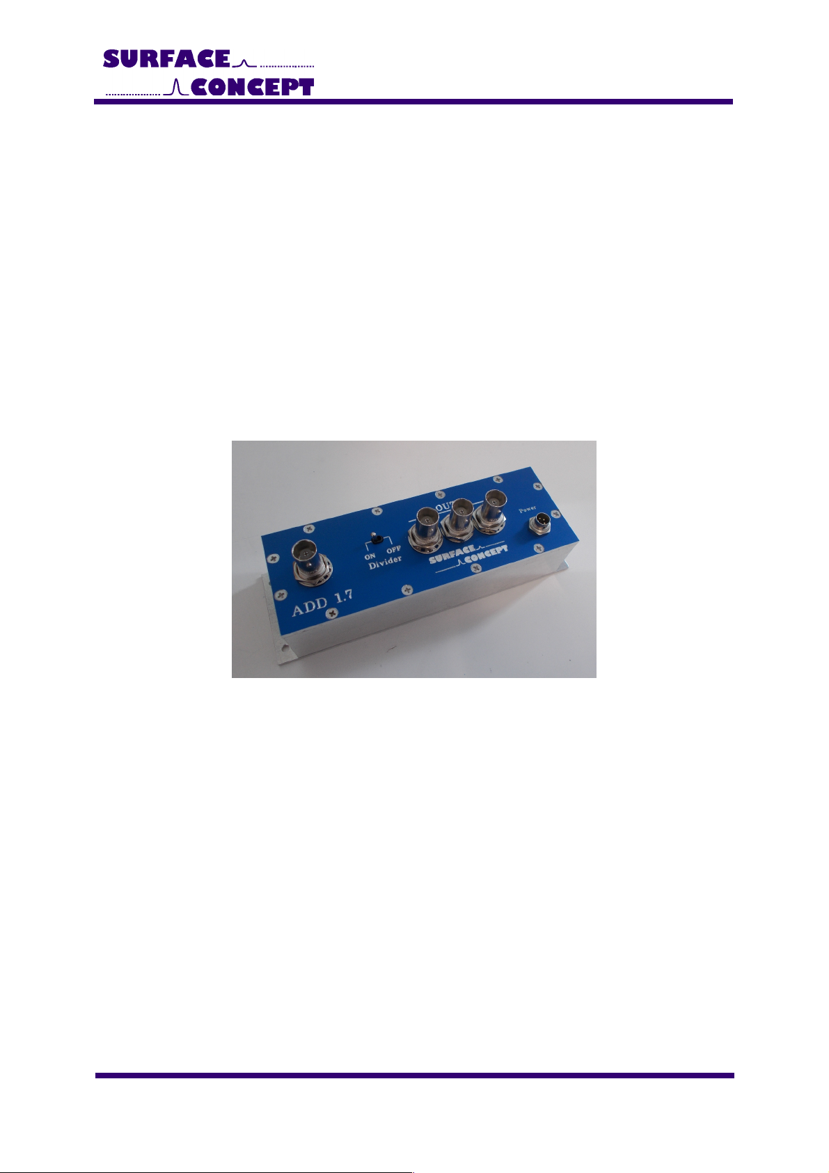
The connector layout of the ADD 1.7 is shown in Figure 1.
Figure 1: Connector Layout of ADD 1.7
1. BNC Socket for Signal Input
(LVTTL).
2. Switch for switching the
frequency dividing factor
between 1 (OFF) and 16 (ON).
. BNC Sockets for -fold FAN
OUT of Signal Output (LVTTL).
4. 5 pin socket for power supply.
7
ADD 1.7 - Manual
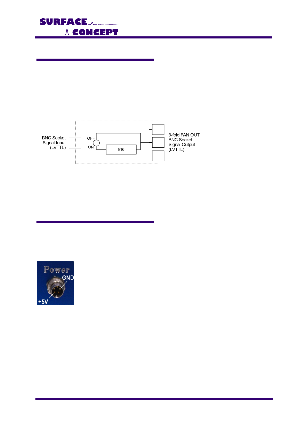
3.3 Schematic Layout and Device Functioning
The 16-fold frequency divider has a BNC connector for the input signal which must be a low voltage (LV)TTL,
but is TTL tolerant. The frequency of the input signal is divided by a frequency dividing factor and is given out
on three BNC connectors which are connected via a -fold FAN OUT. The output signal is a LVTTL signal
again.
The frequency dividing factor can be switched between 1 (OFF) and 16 (ON).
The schematic layout of the ADD 1.7 is given below in Figure 2.
Figure : Schematic layout of ADD 1.7
3.4 Power Supply
The operation power for the ADD 1.7 is +5V. It is provided via a wall power supply. Connect the wall power
supply to the round 5pin socket named “power” of the ADD 1.7. The pin configuration of the 5pin socket is
shown below in Figure .
Figure 3: Pin configuration of 5pin power socket of ADD 1.7.
8

ADD 1.7 - Manual
4 Technical Data
Layout and Performance:
No. of Input Channels: 1
Signal Level for Input Signal: Low voltage TTL (but TTL tolerant)
Connector Type for Input Signal: BNC
No. of Output Channels: (as -fold FAN OUT)
Signal Level of Output Signal: Low voltage TTL
Connector Type of Output Signal: BNC
Frequency Dividing Factor (switchable): 1 or 16
Input Frequency (max.): 100 MHz/ 15MHz (with divider switched ON/ OFF)
Line Input:
Electrical Input (LINE): +5 V (provided by a wall power supply)
Power: Watt (max.)
9
Table of contents
Popular Commercial Food Equipment manuals by other brands


Diamond
Diamond AL1TB/H2-R2 Installation, Operating and Maintenance Instruction

Salva
Salva IVERPAN FC-18 User instructions

Allure
Allure Melanger JR6t Operator's manual

saro
saro FKT 935 operating instructions

Hussmann
Hussmann Rear Roll-in Dairy Installation & operation manual

Cornelius
Cornelius IDC PRO 255 Service manual

Moduline
Moduline HSH E Series Service manual

MINERVA OMEGA
MINERVA OMEGA DERBY 270 operating instructions

Diamond
Diamond OPTIMA 700 Installation, use and maintenance instructions

Diamond
Diamond G9/PLCA4 operating instructions

Cuppone
Cuppone BERNINI BRN 280 Installation

Arneg
Arneg Atlanta Direction for Installation and Use