SurfRAID TRITON 16Ni User manual
SurfRAID TRITON 16Ni
User’s Guide
Revision 1.1

Table of Contents
Preface
FCC Compliance Statement
Before You Begin
PART I Hardware Components and RAID Subsystem
Chapter 1 Introduction
1.1 Key Features
1.2 Technical Specifications
1.3 RAID Concepts
1.4 Array Definition
1.4.1 Raid Set
1.4.2 Volume Set
1.5 High Availability
1.5.4.1 Creating Hot Spares
1.5.4.2 Hot-Swap Disk Drive Support
1.5.4.3 Hot-Swap Disk Rebuild
Chapter 2 Installation Overview
2.1 Packaging, Shipment and Delivery
2.2 Unpacking the NAS System
2.3 Identifying Parts of the SR-TRITON16Ni System
2.3.1 Front View
2.3.2 Rear View
Chapter 3 Getting Started with the SR-TRITON16Ni
3.1
Connecting the SR-TRITON16Ni to your Network
3.2 Powering On
3.3 Installing Hard Drives
3.4 Connecting SAS JBOD Disk Drive Enclosures
Chapter 4 Internal RAID Configuration Utility Options
4.1 Configuration through VT100 Terminal
4.2 Configuration through the LCD Panel
4.2.1 Menu Diagram
4.3 Configuring Internal RAID controller via through web browser-based
"!!
Chapter 5 RAID Management
#%$
#%$#%$
#%$
5.1 Quick Function
"!'&
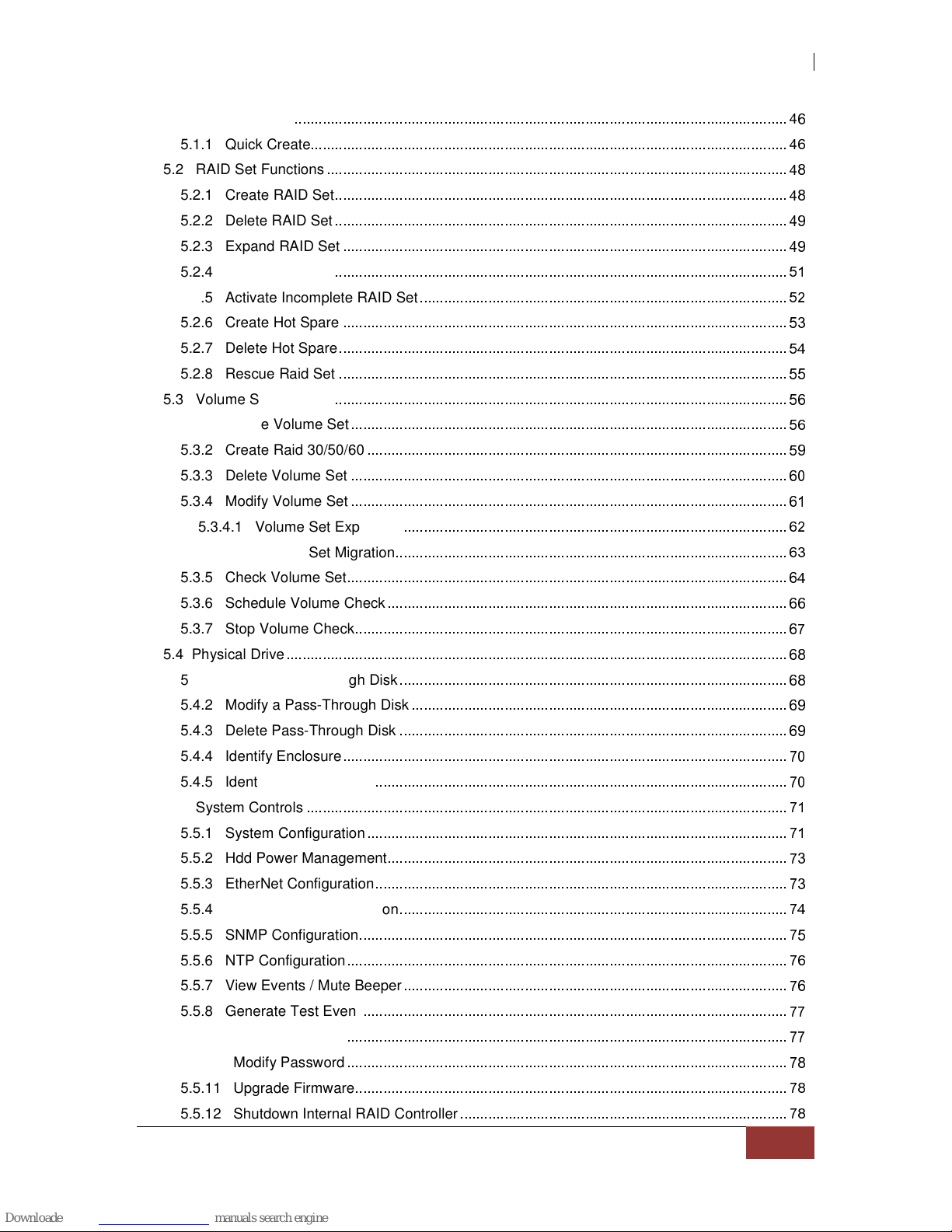
5.1.1 Quick Create
"!'&
5.2 RAID Set Functions
"!'
5.2.1 Create RAID Set
"!'
5.2.2 Delete RAID Set
"!'
5.2.3 Expand RAID Set
"!'
5.2.4 Offline RAID Set
5.2.5 Activate Incomplete RAID Set
5.2.6 Create Hot Spare
5.2.7 Delete Hot Spare
(!
5.2.8 Rescue Raid Set
5.3 Volume Set Function
&
5.3.1 Create Volume Set
&
5.3.2 Create Raid 30/50/60
5.3.3 Delete Volume Set
&
5.3.4 Modify Volume Set
&
5.3.4.1 Volume Set Expansion
&
5.3.4.2 Volume Set Migration
&
5.3.5 Check Volume Set
&(!
5.3.6 Schedule Volume Check
&&
5.3.7 Stop Volume Check
&
5.4 Physical Drive
&
5.4.1 Create Pass-Through Disk
&
5.4.2 Modify a Pass-Through Disk
&
5.4.3 Delete Pass-Through Disk
&
5.4.4 Identify Enclosure
5.4.5 Identify Selected Drive
5.5 System Controls
)
5.5.1 System Configuration
)
5.5.2 Hdd Power Management
5.5.3 EtherNet Configuration
5.5.4 Alert By Mail Configuration
*!
5.5.5 SNMP Configuration
5.5.6 NTP Configuration
&
5.5.7 View Events / Mute Beeper
&
5.5.8 Generate Test Event
5.5.9 Clear Event Buffer
5.5.10 Modify Password
5.5.11 Upgrade Firmware
5.5.12 Shutdown Internal RAID Controller
5.5.13 Restart Internal RAID Controller
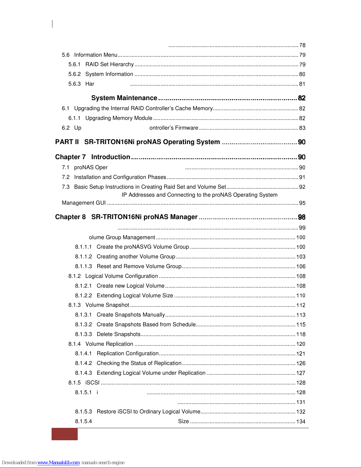
5.6 Information Menu
5.6.1 RAID Set Hierarchy
5.6.2 System Information
5.6.3 Hardware Monitor
Chapter 6 System Maintenance
6.1 Upgrading the Internal RAID Controller’s Cache Memory
6.1.1 Upgrading Memory Module
6.2 Upgrading the Internal RAID Controller’s Firmware
PART II SR-TRITON16Ni proNAS Operating System
Chapter 7 Introduction
7.1 proNAS Operating System Key Components
7.2 Installation and Configuration Phases
7.3 Basic Setup Instructions in Creating Raid Set and Volume Set
7.4 Setting up proNAS IP Addresses and Connecting to the proNAS Operating System
Management GUI
Chapter 8 SR-TRITON16Ni proNAS Manager
8.1 Volume Manager
8.1.1 Volume Group Management
+
8.1.1.1 Create the proNASVG Volume Group
+
8.1.1.2 Creating another Volume Group
+
8.1.1.3 Reset and Remove Volume Group
+ &
8.1.2 Logical Volume Configuration
+
8.1.2.1 Create new Logical Volume
+
8.1.2.2 Extending Logical Volume Size
+
8.1.3 Volume Snapshot
8.1.3.1 Create Snapshots Manually
+
8.1.3.2 Create Snapshots Based from Schedule
8.1.3.3 Delete Snapshots
8.1.4 Volume Replication
8.1.4.1 Replication Configuration
8.1.4.2 Checking the Status of Replication
&
8.1.4.3 Extending Logical Volume under Replication
8.1.5 iSCSI
8.1.5.1 iSCSI Configuration
8.1.5.2 Disable iSCSI in Logical Volume
+)
8.1.5.3 Restore iSCSI to Ordinary Logical Volume
+
8.1.5.4 Extending iSCSI Logical Volume Size
+*!

8.2 Network Manager
+ &
8.2.1 Network Settings and Trunking Setup
+ &
8.2.2 Internet Gateway
!
8.2.3 SNMP/MRTG
!,
8.2.4 Network Test
!'
8.3 Account Manager
!
8.3.1 External Accounts Integration (Joining Windows or NIS Domain)
!
8.3.1.1 Windows Authentication
!
8.3.1.2 Sample Steps to Join the NAS to Windows AD Domain:
!!
8.3.1.3 NIS Authentication
!'
8.3.1.4 Sample Steps to Join NIS Domain:
!'&
8.3.2 Local Account and Group Management
!'&
8.4 Share Manager
(!
8.4.1 Share Management
8.4.1.1 Creating a New Share
8.4.1.2 Applying ACL
&
8.4.1.3 Modifying a Share
&
8.4.1.4 Deleting a Share
8.4.2 Properties Setting
8.4.2.1 Steps to Make a Share Folder a Public Folder Accessible to All Users:
8.4.3 Protocol Setting
&
8.4.3.1 CIFS
&
8.4.3.2 NFS
&
8.4.4 Privilege Setting (Permission)
&
8.4.4.1 Group
&
8.4.4.2 Account
&
8.4.4.3 IP Address
&
8.4.5 Rsync
&
8.4.6 Duplication
+
8.4.7 Default Share
+ &
8.5 System Manager
+
8.5.1 Information tab
+
8.5.2 Upgrade tab
+
8.5.3 Report tab
8.5.4 Time tab
8.5.5 Serial Ports tab
8.5.6 Power tab
8.5.7 Reboot tab
(!
8.5.8 Service tab
8.5.9 Status tab
8.5.10 MRTG tab
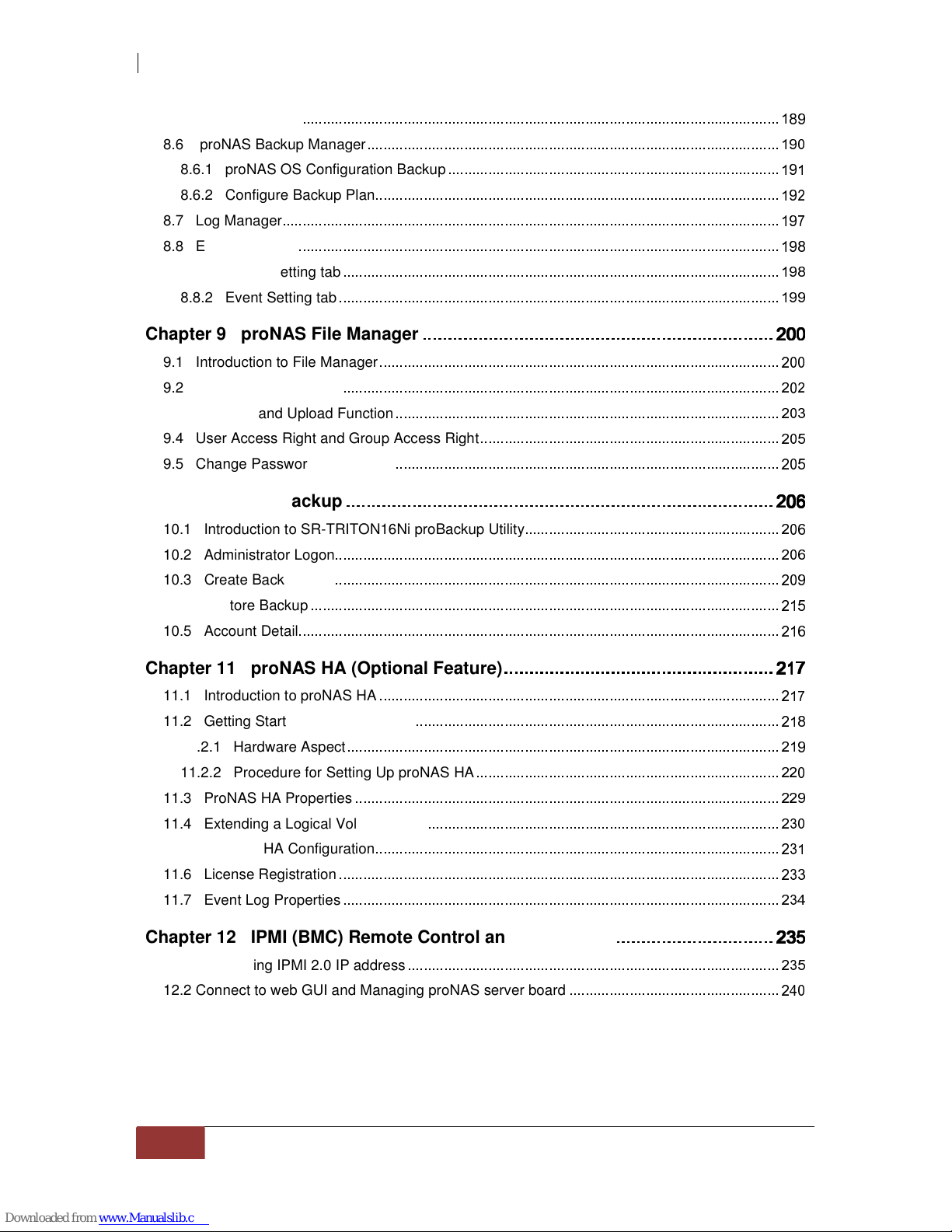
8.6 proNAS Backup Manager
8.6.1 proNAS OS Configuration Backup
8.6.2 Configure Backup Plan
8.7 Log Manager
8.8 Event Manager
8.8.1 E-mail Setting tab
8.8.2 Event Setting tab
Chapter 9 proNAS File Manager
-.
..
.
9.1 Introduction to File Manager
9.2 Logon to File Manager
9.3 Directory and Upload Function
9.4 User Access Right and Group Access Right
9.5 Change Password and Logout
Chapter 10 proBackup
-.$
.$.$
.$
10.1 Introduction to SR-TRITON16Ni proBackup Utility
&
10.2 Administrator Logon
&
10.3 Create Backup Plan
10.4 Restore Backup
10.5 Account Detail
&
Chapter 11 proNAS HA (Optional Feature)
-/
/
/
/
11.1 Introduction to proNAS HA
+
11.2 Getting Started with proNAS HA
11.2.1 Hardware Aspect
11.2.2 Procedure for Setting Up proNAS HA
11.3 ProNAS HA Properties
11.4 Extending a Logical Volume in HA
11.5 Clear All HA Configuration
)
11.6 License Registration
11.7 Event Log Properties
*!
Chapter 12 IPMI (BMC) Remote Control and Monitoring
-.0
.0.0
.0
12.1
Configuring IPMI 2.0 IP address
12.2 Connect to web GUI and Managing proNAS server board
(!

Preface
About this manual
his User Guide provides information regarding the hardware features, installation and
configuration of the SurfRAID TRITON16Ni NAS-SAS/SATA II RAID System. This
document also describes the use of the storage management software. Information
contained in the manual has been reviewed for accuracy, but not for product warranty
because of the various environment/OS/settings. Information and specifications will be
changed without further notice. Some pictures and screenshots might be different with the
actual machine.
This manual uses section numbering for every topic being discussed for easy and convenient way of
finding information in accordance with the user’s needs. The following icons are being used for some
details and information to be considered in going through with this manual:
Copyright
No part of this publication may be reproduced, stored in a retrieval system, or transmitted in any
form or by any means, electronic, mechanical, photocopying, recording or otherwise, without the
prior written consent by Partners Data Systems, Inc.
Trademarks
All products and trade names used in this document are trademarks or registered trademarks of
their respective owners.
Changes
The material in this document is for information only and is subject to change without notice.

FCC Compliance Statement
This equipment has been tested and found to comply with the limits for a Class B digital device,
pursuant to Part 15 of the FCC rules. These limits are designed to provide reasonable protection
against harmful interference in residential installations. This equipment generates, uses, and can
radiate radio frequency energy, and if not installed and used in accordance with the instructions, may
cause harmful interference to radio communications.
However, there is no guarantee that interference will not occur in a particular installation. If this
equipment does cause interference to radio or television equipment reception, which can be
determined by turning the equipment off and on, the user is encouraged to try to correct the
interference by one or more of the following measures:
1. Reorient or relocate the receiving antenna
2. Move the equipment away from the receiver
3. Plug the equipment into an outlet on a circuit different from that to which the receiver is
powered.
4. Consult the Partners Data Systems or an experienced radio/television technician for help
All external connections should be made using shielded cables

Before You Begin
efore going through this User Guide, you should read and focus on the following safety
guidelines. To provide reasonable protection against any harm on the part of the user
and to obtain maximum performance, user is advised to be aware of the following
safety guidelines particularly in handling hardware components:
Upon receiving of the product:
Place the product in its proper location.
To avoid unnecessary dropping of subsystem, make sure that somebody available to help
with moving of the subsystem.
Subsystem should be handled with care to avoid dropping that may cause damage to the
product. Always use the correct lifting procedures.
Upon installing of the product:
Ambient temperature is very important for the installation site. It must not exceed 30°C. Due
to seasonal climate changes; regulate the installation site temperature making it not to exceed
the allowed ambient temperature.
Before plugging-in any power cords, cables and connectors, make sure that the power
switches are turned off. Disconnect first any power connection if the power supply module is
being removed from the enclosure.
Outlets must be accessible to the equipment.
All external connections should be made using shielded cables and as much as possible
should not be performed by bare hand. Using anti-static hand gloves is recommended.
In installing each component, secure all the mounting screws and locks. Make sure that all
screws are fully tightened. Follow correctly all the listed procedures in this manual for reliable
performance.
Controller Configuration
The SR-TRITON16Ni subsystem supports a single RAID controller and motherboard
configuration. Please contact Partners Data systems for higher available configurations
using the SR-TRITON16Ni.
Packaging, Shipment and Delivery
Before removing the subsystem from the shipping carton, you should visually inspect the
physical condition of the shipping carton.
Unpack and verify that the contents of the shipping carton are complete and in good condition.
Exterior damage to the shipping carton may indicate that the contents of the carton are
damaged.
If any damage is found, do not remove the components; please contact your Partners Data
Systems’ account manager or tech support personnel for further instructions.
Partners Data Systems
3663 Via Mercado
La Mesa, CA. 91941
800-550-3005
www.partnersdata.com
support@partnersdata.com

PART I Hardware Components and RAID Subsystem
Chapter 1 Introduction
The SurfRAID TRITON NAS-SAS/SATAII RAID System
Companies are looking for cost-effective storage solutions which can offer the best
performance, high scalability and reliability. As the number of users and the amount of data
grows, Network Attached Storage is becoming a critical technology and the need for an
optimized solution is becoming an important requirement.
Partners Data Systems delivers the SurfRAID TRITON16Ni NAS-SAS/SATA II RAID System,
which combines direct attached storage (DAS), iSCSI target device and network attached
storage (NAS) solution for flexible and expandable application, and together with the proNAS
management solution, proNAS High-Availability and proBackup client backup solution, provide
businesses with the most flexible, scalable, securable and manageable NAS environment. It
helps to control the total cost of ownership for data management.
The SurfRAID TRITON16Ni is an NAS/DAS/iSCSI all in one Subsystem with proNAS Operating
System. It enhances system availability, and manages complex storage environments easily.
For improving business productivity and minimizing business risks, SurfRAID TRITON16Ni
provides a volume replication and a volume snapshot function. It is also a full featured data
protection system supporting RAID levels 0, 1, 10(1E), 3, 5, 6, 30, 50, 60 and JBOD. It supports
hot spares, automatic hot rebuild and online capacity expansion within the enclosure.

1.1 Key Features
- Configurable to 19" rack-mountable 3U chassis
- RAID Controller = INTEL 800Mhz IOP341 CPU
- System Motherboard = INTEL Xeon E5505@2Ghz x1, 4 Cores
- Up to Sixteen (16) 1" hot - swappable 3G SAS/SATA II hard drives
- RAID levels 0, 1, 10(1E), 3, 5, 6, 30, 50, 60 and JBOD
- Supports NAS, DAS and iSCSI in one system
- Two Gigabit Ethernet port for NAS file-sharing application
- One SAS port for direct access of RAID host connection
- Supports iSCSI target for block level of IP storage environment
- Maximal support up to 112 SAS/SATAII disks totally based on:
* Supports one SAS Expansion port to connect up to 6 SAS JBOD enclosures for RAID expansion
(up to 112 disks), using SR-TRITON16JS3 JBOD chassis
- Smart-function LCD panel for RAID setting & ENC status
- Supports hot spare and automatic hot rebuild.
- Allows online capacity expansion within the enclosure
- Support spin down drives for power saving (MAID) and disk drive power cycle
- Scheduled volume check data correctness for RAID 3/5/6
- 64 bit Linux-based embedded system
- Centralization of Data and Storage Management
- Using Market-Leading Java Technology
- Latest volume snapshot technology
- Apply volume replication to enhance data protection
- Support logical volume over 2TB (Maximum 8 Exabytes, 16TB max for Replication and HA)
- Data Backup via backup plan and scheduling
- Enhance system configuration backup
- Local and external account management, support large account import
- Share management and permission (support ACL setting)
- Support Internet Gateway function
- Online expansion of file systems
- Support E-mail notification and system log information
- Multi application support via proFamily Software
- Internal RAID controller supports up to 128 RAID Sets, Volume Sets and Host LUNs
- Remote IPMI (BMC) Management for remote notification and power ON/OFF control
1.2 Technical Specifications
Model Number : SurfRAID TRITON16Ni
Hardware Platform
Intel Quad Core Xeon 2.0G or above, single / dual Processor
Cache memory
1
3GB DDR3 SDRAM up to 32GB
Two Gigabit Ethernet ports (10 Gigabit Ethernet for additional option)
Up to Sixteen 1" hot-swappable SAS/SATA II (3Gb/s, NCQ support) hard drives
Real time drive activity and status indicators
Environmental monitoring unit
Two(2) 700W hot-swap power supplies with PFC
Expansion PCI slots for H/W upgrade
One (1) 4X SAS Host port for RAID connection to a Host System (volume created from enclosure
is used by other host system)
One (1) 4X SAS Expansion port for JBOD connection (up to 6 SAS JBOD enclosures, max. 112
disks) using SR-TRITON16JS3 JBOD chassis
RAID Controller Specifications
Intel IOP341 64 bit RISC
Supports RAID level: RAID 0, 1, 10(1E), 3, 5, 6, 30, 50, 60 and JBOD
Supports 512MB up to 2GB of ECC cache memory
Supports hot spare and automatic hot rebuild
Support MAID (spin down drives when not in use to extend service)
Allows online capacity expansion within the enclosure
Built-in interfaces for remote event notification
Local audible event notification alarm
Storage Management
Volume Management
Disk usage statistics
Hot spare capability
General
File Server Independent
Multiple language support
Support UPS management
System Management
Automatic IP address configuration
Self-contained unit - no extra software needed
Management through Web browser
Flash upgradeable subsystem
SNMP / MRTG management and notification
Fail-free online firmware upgrade
Unicode support
Multi-node Management GUI
proNAS Data and Configuration Backup
Central Management
Networking
Supports NIC Trunking types; Fault Tolerant, Load Balance, Fault Tolerant and Load Balance, and
Link Aggregation 802.3ad
DHCP Server / DHCP Client
WINS Server
Internet gateway
Protocols
TCP/IP, SMB/CIFS, NFS, SNMP, FTP/SFTP/FXP, HTTP, Telnet, SSH
Supported Client Operating Systems
Microsoft® Windows® 2000 / XP / 2003 / Vista / 7 / 2008
Unix; Solaris 8, 9, 10, Linux; Redhat kernel 2.6 and above, SUSE ES 9, 10
Mac OS X 10.5 and above

Authentication
Local User Account/Group
Microsoft NT Domain Controller (PDC)
Microsoft Active Directory Authentication (ADS)
Network Information Service (NIS)
Support batch creating users/Group
User quota management
Share level security
File level security
User ID security for NFS
Block Storage
iSCSI and SAS Target Support
Data Backup / Restore
Scheduling Multi-Snapshot
Replication (Requires two SR-TRITON16Ni subsystems)
Duplication
Scheduling Rsync Replication
proBackup (backup from client to NAS) and Symantec Backup Exec RALUS agent for Linux
Support CDP Server (Optional), contact Partner Data Systems for details
High Availability
proNAS High Availability (Optional), requires two SR-TRITON16Ni subsystems
Power requirements
AC 100V ~ 240 Full range
12A ~ 6A, 50~60Hz
Physical Dimension
133(H) x 482(W) x 716(D) mm
Note: Specifications are subject to change without notice. All company and product names are
trademarks of their respective owners.
1.3 RAID Concepts
RAID Fundamentals
The basic idea of RAID (Redundant Array of Independent Disks) is to combine multiple inexpensive
disk drives into an array of disk drives to obtain performance, capacity and reliability that exceeds that
of a single large drive. The array of drives appears to the host computer as a single logical drive.
Five types of array architectures, RAID 1 through RAID 5, were originally defined; each provides disk
fault-tolerance with different compromises in features and performance. In addition to these five
redundant array architectures, it has become popular to refer to a non-redundant array of disk drives
as a RAID 0 arrays.
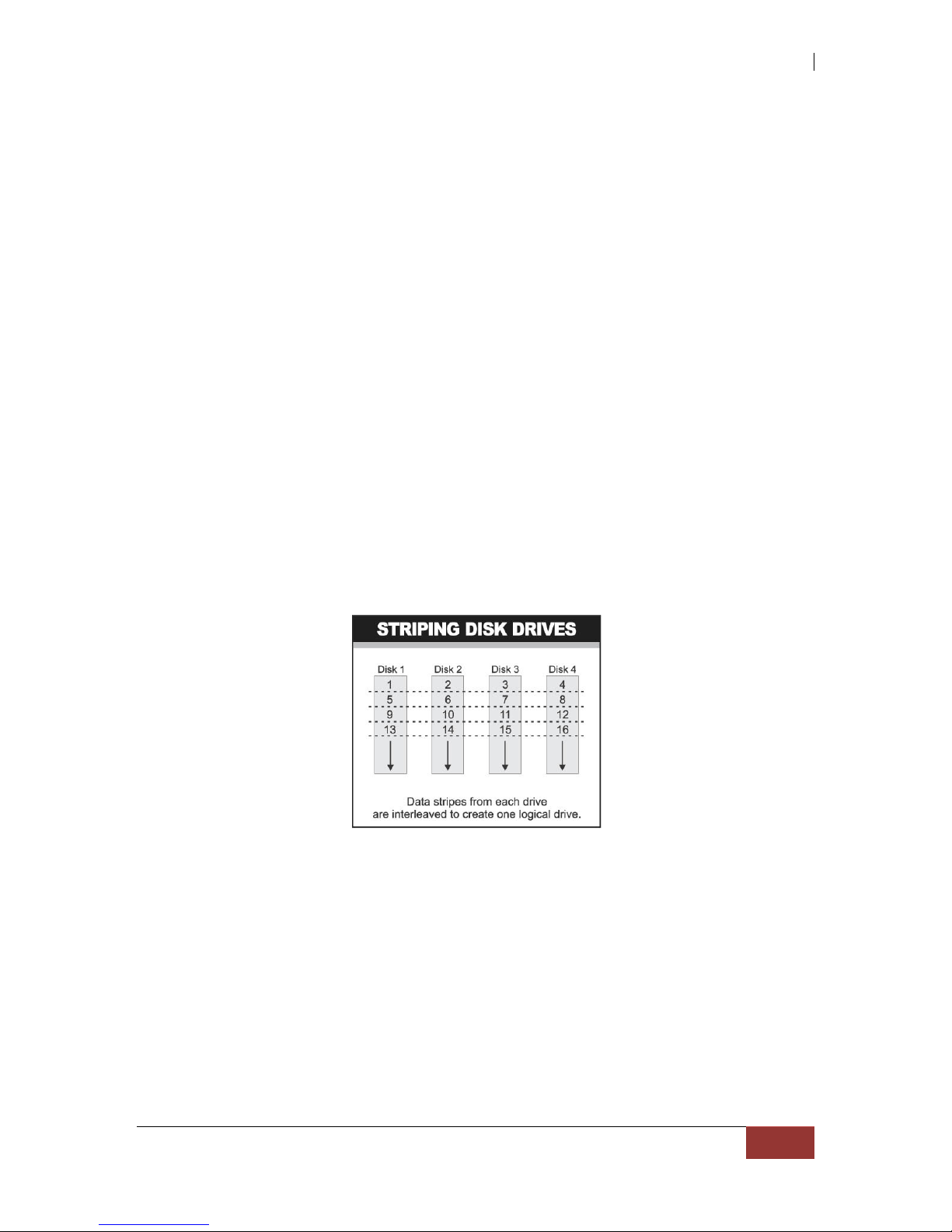
Disk Striping
Fundamental to RAID technology is striping. This is a method of combining multiple drives into one
logical storage unit. Striping partitions the storage space of each drive into stripes, which can be as
small as one sector (512 bytes) or as large as several megabytes. These stripes are then interleaved
in a rotating sequence, so that the combined space is composed alternately of stripes from each drive.
The specific type of operating environment determines whether large or small stripes should be used.
Most operating systems today support concurrent disk I/O operations across multiple drives. However,
in order to maximize throughput for the disk subsystem, the I/O load must be balanced across all the
drives so that each drive can be kept busy as much as possible. In a multiple drive system without
striping, the disk I/O load is never perfectly balanced. Some drives will contain data files that are
frequently accessed and some drives will rarely be accessed.
By striping the drives in the array with stripes large enough so that each record falls entirely within one
stripe, most records can be evenly distributed across all drives. This keeps all drives in the array busy
during heavy load situations. This situation allows all drives to work concurrently on different I/O
operations, and thus maximize the number of simultaneous I/O operations that can be performed by
the array.
Definition of RAID Levels
RAID 0 is typically defined as a group of striped disk drives without parity or data redundancy. RAID 0
arrays can be configured with large stripes for multi-user environments or small stripes for single-user
systems that access long sequential records. RAID 0 arrays deliver the best data storage efficiency
and performance of any array type. The disadvantage is that if one drive in a RAID 0 array fails, the
entire array fails.

RAID 1, also known as disk mirroring, is simply a pair of disk drives that store duplicate data but
appear to the computer as a single drive. Although striping is not used within a single mirrored drive
pair, multiple RAID 1 arrays can be striped together to create a single large array consisting of pairs of
mirrored drives. All writes must go to both drives of a mirrored pair so that the information on the
drives is kept identical. However, each individual drive can perform simultaneous, independent read
operations. Mirroring thus doubles the read performance of a single non-mirrored drive and while the
write performance is unchanged. RAID 1 delivers the best performance of any redundant array type.
In addition, there is less performance degradation during drive failure than in RAID 5 arrays.
RAID 3 sector-stripes data across groups of drives, but one drive in the group is dedicated for storing
parity information. RAID 3 relies on the embedded ECC in each sector for error detection. In the case
of drive failure, data recovery is accomplished by calculating the exclusive OR (XOR) of the
information recorded on the remaining drives. Records typically span all drives, which optimizes the
disk transfer rate. Because each I/O request accesses every drive in the array, RAID 3 arrays can
satisfy only one I/O request at a time. RAID 3 delivers the best performance for single-user, single-
tasking environments with long records. Synchronized-spindle drives are required for RAID 3 arrays in
order to avoid performance degradation with short records. RAID 5 arrays with small stripes can yield
similar performance to RAID 3 arrays.

Under RAID 5 parity information is distributed across all the drives. Since there is no dedicated parity
drive, all drives contain data and read operations can be overlapped on every drive in the array. Write
operations will typically access one data drive and one parity drive. However, because different
records store their parity on different drives, write operations can usually be overlapped.
Dual-level RAID achieves a balance between the increased data availability inherent in RAID 1 and
RAID 5 and the increased read performance inherent in disk striping (RAID 0). These arrays are
sometimes referred to as RAID 0+1 or RAID 1+0 and RAID 0+5 or RAID 50.
RAID 6 is similar to RAID 5 in that data protection is achieved by writing parity information to the
physical drives in the array. With RAID 6, however, two sets of parity data are used. These two sets
are different, and each set occupies a capacity equivalent to that of one of the constituent drives. The
main advantage of RAID 6 is High data availability – any two drives can fail without loss of critical data.

In summary:
RAID 0 is the fastest and most efficient array type but offers no fault-tolerance. RAID 0 requires a
minimum of one drive.
RAID 1 is the best choice for performance-critical, fault-tolerant environments. RAID 1 is the only
choice for fault-tolerance if no more than two drives are used.
RAID 3 can be used to speed up data transfer and provide fault-tolerance in single-user
environments that access long sequential records. However, RAID 3 does not allow overlapping
of multiple I/O operations and requires synchronized-spindle drives to avoid performance
degradation with short records. RAID 5 with a small stripe size offers similar performance.
RAID 5 combines efficient, fault-tolerant data storage with good performance characteristics.
However, write performance and performance during drive failure is slower than with RAID 1.
Rebuild operations also require more time than with RAID 1 because parity information is also
reconstructed. At least three drives are required for RAID 5 arrays.
RAID 6 is essentially an extension of RAID level 5 which allows for additional fault tolerance by
using a second independent distributed parity scheme (two-dimensional parity). Data is striped on
a block level across a set of drives, just like in RAID 5, and a second set of parity is calculated
and written across all the drives; RAID 6 provides for an extremely high data fault tolerance and
can sustain multiple simultaneous drive failures. It is a perfect solution for mission critical
applications.

Internal RAID Management
The subsystem can implement several different levels of RAID technology. RAID levels supported by
the subsystem are shown below.
RAID Level Description Min. Drives
0
Block striping is provide, which yields higher
performance than with individual drives. There is no
redundancy.
1
1 Drives are paired and mirrored. All data is 100%
duplicated on an equivalent drive. Fully redundant. 2
3 Data is striped across several physical drives. Parity
protection is used for data redundancy. 3
5 Data is striped across several physical drives. Parity
protection is used for data redundancy. 3
6
Data is striped across several physical drives. Parity
protection is used for data redundancy. Requires N+2
drives to implement because of two-dimensional parity
scheme.
4
10 (1E)
Combination of RAID levels 0 and 1. This level provides
striping and redundancy through mirroring. RAID 10
requires the use of an even number of disk drives to
achieve data protection, while RAID 1E (Enhanced
Mirroring) uses an odd number of drives.
4 (3)
30
Combination of RAID levels 0 and 3. This level is best
implemented on two RAID 3 disk arrays with data
striped across both disk arrays.
6
50
RAID 50 provides the features of both RAID 0 and RAID
5. RAID 50 includes both parity and disk striping across
multiple drives. RAID 50 is best implemented on two
RAID 5 disk arrays with data striped across both disk
arrays.
6
60
RAID 60 combines both RAID 6 and RAID 0 features.
Data is striped across disks as in RAID 0, and it uses
double distributed parity as in RAID 6. RAID 60
provides data reliability, good overall performance and
supports larger volume sizes.
RAID 60 also provides very high reliability because data
is still available even if multiple disk drives fail (two in
each disk array).
8

1.4 Array Definition
1.4.1 Raid Set
A Raid Set is a group of disk drives containing one or more logical volumes called Volume Sets. It is
not possible to have multiple Raid Sets on the same disk drives.
A Volume Set must be created either on an existing Raid Set or on a group of available individual
disk drives (disk drives that are not yet a part of a Raid Set). If there are existing Raid Sets with
available raw capacity, new Volume Set can be created. New Volume Set can also be created on
an existing Raid Set without free raw capacity by expanding the Raid Set using available disk
drive(s) which is/are not yet Raid Set member. If disk drives of different capacity are grouped
together in a Raid Set, then the capacity of the smallest disk will become the effective capacity of all
the disks in the Raid Set.
1.4.2 Volume Set
A Volume Set is seen by the host system as a single logical device. It is organized in a RAID level
with one or more physical disks. RAID level refers to the level of data performance and protection
of a Volume Set. A Volume Set capacity can consume all or a portion of the raw capacity
available in a Raid Set. Multiple Volume Sets can exist on a group of disks in a Raid Set.
Additional Volume Sets created in a specified Raid Set will reside on all the physical disks in the
Raid Set. Thus each Volume Set on the Raid Set will have its data spread evenly across all the
disks in the Raid Set. Volume Sets of different RAID levels may coexist on the same Raid Set.
In example, Volume 1 can be assigned a RAID 5 RAID level while Volume 0 might be assigned a
RAID 10 RAID level.
Table of contents


