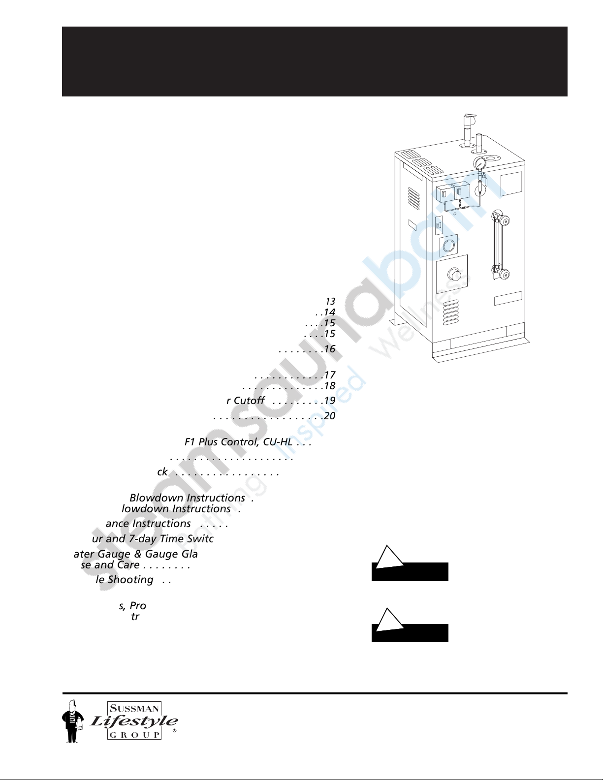
MrSteam CU Series
Installation, Operating & Maintenance Manual
5
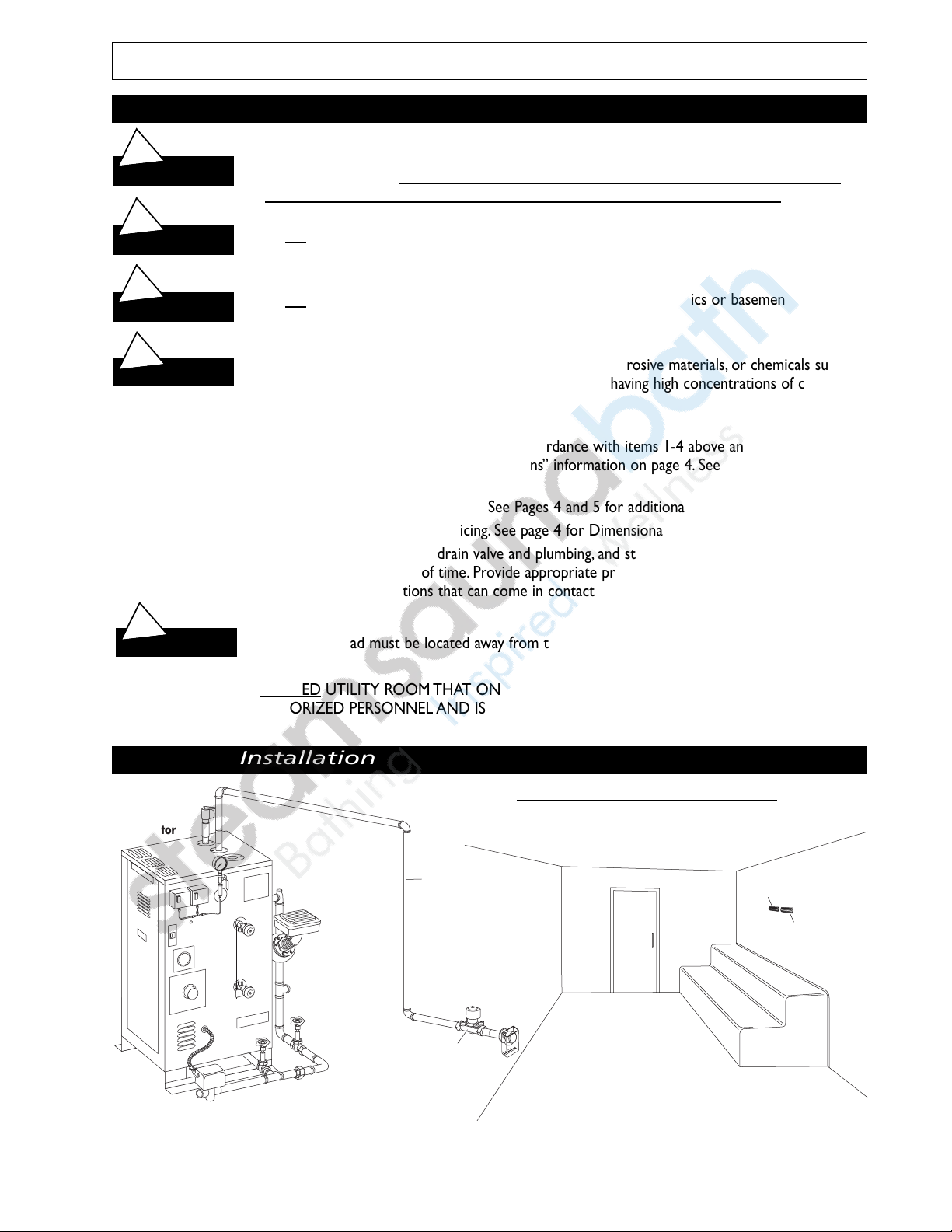
Selecting a
MrSteam
CU Series Generator
The resultant calculated volume of the steam room determines the Model CU steambath generator required. Steam
room size and additional constructional factors affect model selected.
A.
To determine the steam room volume first multiply Length x Width x Height of the steam room.
_______________________________________________________________________________________________
Example:
A steam room 8' x 9' x 8' = 576 Cu.Ft. (volume).
Select the MrSteam Model which is the next larger volume. In this example, Model CU-750 is the correct selection.
Example:
2 Steam rooms each 6' x 10' x 7' x 2 rooms = 840 Cu. Ft. (volume).
In this example, Model CU-1000 is the correct selection.
NOTE:
Insure adequate consideration is given to assure that the CU unit selected is not undersized for the room.
_______________________________________________________________________________________________
B. NOTE:
Certain additional factors effect the correct sizing of the steambath generator:
1.
Construction materials such as glass or glass block, natural marble or other stones: Increase volume.
2.
Piping runs longer than 25 feet from the steambath generator to the steam room: Increase volume.
3.
Exterior walls and outside windows: Increase volume.
4.
Steam room with interior height in excess of 8 feet: Increase volume
_______________________________________________________________________________________________
C.
IMPORTANT:
The above selection guidelines are recommendations only. Always consult with contractor
designer or architect. For general information, contact East Coast: 1-800-767-8326 or West Coast: 1-800-727-8326.
_______________________________________________________________________________________________
D.
IMPORTANT:
When specifying a CU Commercial Steambath generator the following is strongly recommend-
ed for best performance and user satisfaction.
1.
One CU steambath generator should service no more that two (2) steam rooms, each relatively similar in size and
construction.
2.
If two (2) steamrooms are serviced by one (1) CU generator, the combined resultant room volume of the two
rooms should not exceed 1000 cubic feet.
3.
Each room must be operated with the appropriate F1 Plus temperature control system inclusive of the room oper-
ating temperature control and the high-limit temperature control.
4.
In any case, the purchase and/or owner/operator must consult with a designer, architect, and/or consultant to
assure the proper specification of the steam generator.
Model No. KW Maximum* Water Inlet Steam Generator Dimensions (inches) Shipping
Room Volume Size NPT Outlet Size, NPT Width Length Height Wt.Lbs.
Cubic Feet
_______________________________
CU-360 9 400 1/2" 1" 20 20 38 250
____________________________________________________________________________________________________
CU-500 12 500 1/2" 1" 20 20 38 250
____________________________________________________________________________________________________
CU-750 18 750 1/2" 1" 20 20 38 250
____________________________________________________________________________________________________
CU-1000 24 1000 1/2" 1" 20 30 38 270
____________________________________________________________________________________________________
CU-1250 30 1250 1/2" 1" 20 30 38 290
____________________________________________________________________________________________________
CU-1400 36 1400 1/2" 1" 20 30 38 300
____________________________________________________________________________________________________
CU-2000 48 2000 1/2" 1" 24 33 44 330
____________________________________________________________________________________________________
CU-2500 60 2500 1/2" 1" 24 33 44 380
____________________________________________________________________________________________________
CU-3000 72 3000 1/2" 1" 24 33 44 390
____________________________________________________________________________________________________
CU-4500 108 4500 3/4" 1-1/2" 28 34 59 625
* After taking into consideration all factors affecting resultant steam room volume, including materials of construction, dis-
tance from generator to steam room, interior height of steam room ceiling, outside/exterior walls and windows etc., select
proper Model CU generator. Consult with architect, designer and contractor before making final selection.