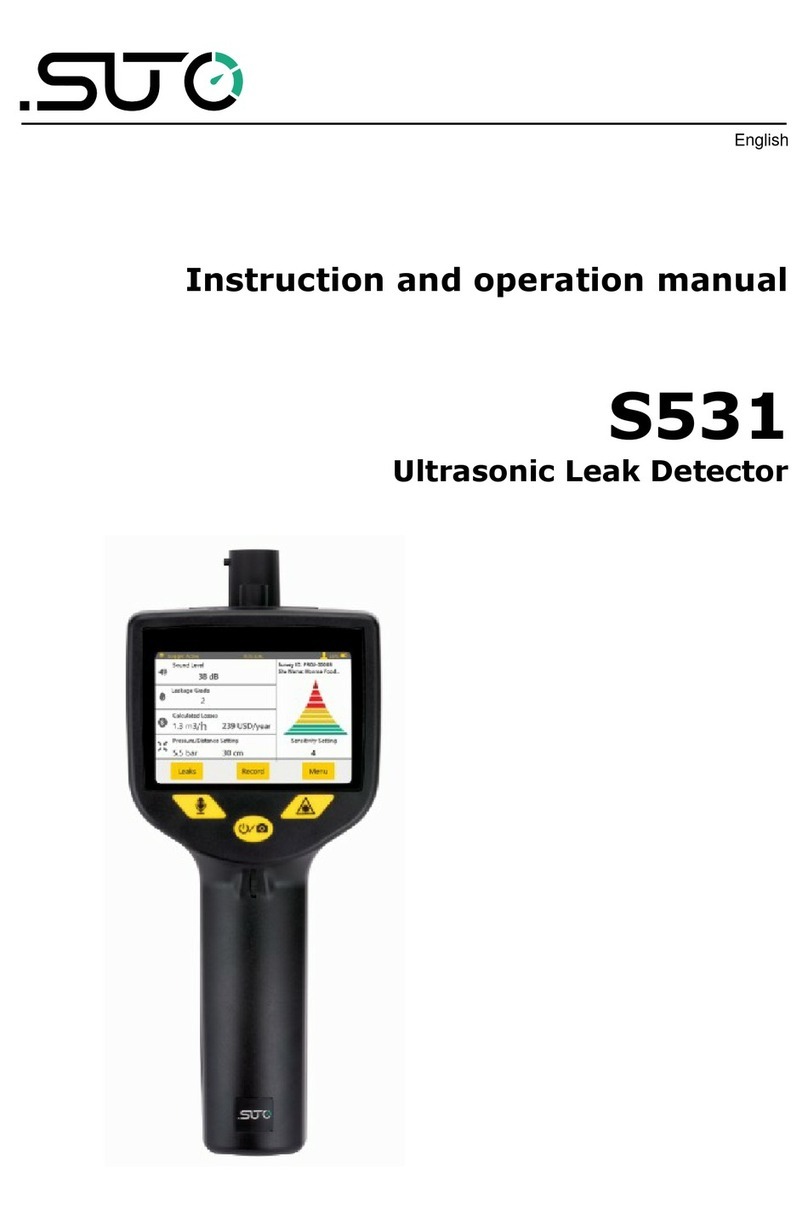
SUTO S531 Manual

English
Instruction and operation manual
S531
Ultrasonic Leak Detector

Dear Customer,
Thank you for choosing our product.
Before you start up the device, please read this manual in full and
carefully observe instructions stated. The manufacturer cannot be held
liable for any damage that occurs as a result of non-observance or non-
compliance with this manual.
Should the device be tampered with in any manner other than a
procedure that is described and specified in the manual, the warranty is
void and the manufacturer is e empt from liability.
The device is designed e clusively for the described application.
SUTO offers no guarantee for the suitability for any other purpose.
SUTO is also not liable for consequential damage resulting from the
delivery, capability or use of this device.
2 S531

Table of Contents
1 Safety instructions .....................................................................5
2 Registered trademarks.................................................................7
3 Application.................................................................................8
4 Features....................................................................................8
5 Technical data............................................................................9
5.1 General data.......................................................................9
5.2 Electrical data......................................................................9
5.3 Performance data...............................................................10
6 Scope of delivery......................................................................11
7 Learning about the device..........................................................12
7.1 Components .....................................................................12
7.2 Touch screen display...........................................................13
7.3 Dimension and electrical ports.............................................15
8 Before you start for the first time................................................16
8.1 Charging the device............................................................16
8.2 Performing initial setup.......................................................16
9 Procedures of detecting leakages ...............................................19
9.1 Create a project ................................................................20
9.2 Specify the measurement setting.........................................20
9.3 Search and locate a leakage................................................21
9.4 Record the leak..................................................................22
9.5 Manage leak record and projects..........................................24
9.5.1 Edit or delete a leak record..................................................24
9.5.2 Edit or delete a project........................................................26
9.6 E port project files ..........................................................28
9.6.1 E port to a USB drive..........................................................28
9.6.2 Copy from S531 to PC ........................................................28
9.7 Import project files to LMS..................................................28
10 Maintenance...........................................................................29
10.1 Self-test..........................................................................29
10.2 Updating the firmware......................................................29
10.3 Resetting the device.........................................................32
10.4 Cleaning the sensor..........................................................32
11 Optional accessories................................................................33
12 Disposal or waste....................................................................33
13 Appendi : Headset overview.....................................................34
13.1 Power on or off................................................................35
S531 3

13.2 Turn on or off Noise Cancellation........................................35
13.3 Switching to the wireless mode..........................................36
13.4 Switching to the wired mode..............................................36
13.5 Pairing a new headset with the S531...................................37
13.6 Care and maintenance......................................................38
4 S531

1 Safety instructions
Please check if this instruction manual matches the
product type
Please observe all notes and instructions indicated in this
manual. It contains essential information which must be
observed before and during installation, operation and
maintenance. Therefore this instruction manual must be read carefully
by the technician as well as by the responsible user or qualified
personnel.
This instruction manual must be available at the operation site of the
leak detector at any time. In case of any obscurities or questions,
regarding this manual or the product, please contact the manufacturer.
WARNING!
Compressed air!
Any contact with quickly escaping air or bursting
parts of the compressed air system can lead to
serious injuries or even death!
•Avoid that persons get hit escaping air or bursting parts of the
system.
WARNING!
Laser pointer!
Do not point into the eyes with the laser It can lead
to serious injuries particularly on lens and retina or
even blindness!
•Never look directly at the laser
•Never point the laser at persons.
•Never point the laser at smooth and reflective surfaces. This can
lead to a reflection of the laser.
WARNING!
Voltage used for supply!
Any contact with energized parts of the product, may
lead to a electrical shock which can lead to serious
injuries or even death!
S531 5

1 Safety instructions
WARNING!
To prevent possible hearing damage, do not listen at
high volume levels for long periods
ATTENTION!
Permitted operating parameters!
Observe the permitted operating parameters, any
operation exceeding this parameters can lead to
malfunctions and may lead to damage on the
instrument
•Do not e ceed the permitted operating parameters.
•Make sure the product is operated in its permitted limitations.
•Do not e ceed or undercut the permitted storage and operation
temperature and pressure.
General safety instructions
•It is not allowed to use the product in e plosive areas.
•Please observe the national regulations before/during operation.
Remarks
•It is not allowed to disassemble the product.
ATTENTION!
Measurement values can be affected by malfunction!
The device must be used properly and frequently
maintained, otherwise it may lead to wrong
measurement values that can lead to wrong results
•Avoid condensation on the leak detector sensor because this will
affect the accuracy enormously.
6 S531

1 Safety instructions
Storage and transportation
•Ensure the transportation temperature is between -20 ... +50°C.
•For transportation it is recommended to use the packaging that
comes with the leak detector.
•Please ensure that the storage temperature of the sensor is
between -10 ... +50°C.
•Avoid direct UV and solar radiation during storage.
•For the storage the humidity must be <90%, no condensation.
2 Registered trademarks
Trademark Trademark owner
SUTO®SUTO iTEC
MODBUS®Modbus Organization, Hopkinton, USA
HART®HART Communication Foundation, Austin, USA
S531 7

3 Application
3 Application
The S531 is a hand-held ultrasonic leak detector that helps you quickly
detect and provides quantitative data for the leakages in compressed air
or any pressurized gas systems.
Gas leaks emit ultrasound, however the frequency is too high to hear by
human ear directly. The S531 converts the leak ultrasound to a lower
frequency that can be heard through headphones from several meters
away, which leads you to find the leak source.
In unpressurised systems, you can use an ultrasonic tone generator to
generate sounds that can be detected by the S531.
To efficiently manage the leak data, SUTO offers the Leak Management
Software (LMS) for your need. The LMS provides a total solution for leak
detection, management and easy report creation.
This manual takes you through how to use the S531.
4 Features
•Detects leaks in the compressed air or gas system easily even
from distance.
•Supports high resolution 3.5” color touch screen, easing
operations in leak detection.
•Supports wireless connection with headset.
•Builds in camera to take photo of leak locations.
•Provides voice recorder for voice memos.
•Equips with laser pointer to pinpoint leak locations.
•Records leak information for statistics and repair.
•Calculates air loss in l/min, m3/h or cfm and in the local currency
•Integrates noise reduction technology.
•Supports battery capacity for up to 6 hours.
8 S531

5 Technical data
5 Technical data
5 1 General data
Principle of
measurement
Ultrasonic leak detection
Measuring medium Compressed Air, refrigerants and any
compressed gases
Jack 3.5 mm stereo phone jack for headset
Operating temperature 0 ... +40°C
Battery life About 6 hours with wireless off
Charging temperature +10 ... +45°C
Charging time Around 3 hours
Materials of the detector PC + ABS
Dimensions See section 7.3.
Interface Wireless connection to headset
USB port for charging and data e change
Display 3.5” color LCD
Laser pointer Wave length: 640 ... 660 nm
Output power: < 1.0 mW
Camera 5.0 megapi els
Headset Noise isolated and wireless
Weight 3.65 kg (full set)
5 2 Electrical data
Power supply Internal lithium-ion battery
S531 9

6 Scope of delivery
6 Scope of delivery
The S531 layout in the transportation case is shown as below.
Please make sure that below components are included in your package.
Qty Description Item No
1 S531 Ultrasonic Leak Detector P560 0104
1 Noise isolated/canceling wireless headset (page 34) A554 0119
1 Focus tube and focus tip (used for leak detection) A530 0101
1 Trumpet (used to increase sensitivity and isolate
from environmental noise)
A554 0123
1 Battery charger A554 0117
1 Type-C USB stick A554 0124
1 Transport case A554 0118
1 Leak tags to mark found leaks, 100 pieces A554 0122
1 Instruction manual NA
1 Calibration certificate NA
Optional accessories:
1 Ultrasonic tone generator A554 0103
1 Calibration for S531 R200 0070
S531 11

7 Learning about the device
This chapter describes components of the S531 main unit.
7 1 Components
Part Description
1Power button: Long press for 2 seconds to turn S531 on or
off. It also works as a shortcut button for taking photos in leak
detection.
2Voice recording button: Click to start recording voice
memos, then click to stop recording during leak detection.
3Laser button: Press to turn laser on or off.
4Sensitivity wheel: Turn the wheel to fine tune the sensitivity
setting. Turn the wheel up to increase the sensitivity and down
to decrease the sensitivity. Turning the sensitivity up or down
makes the volume go up or down.
Note: The sensitivity setting does not impact the sound level
reading.
5Touch screen: for further functions
6Sensor unit: To detect the ultrasound level.
12 S531

7 Learning about the device
7 2 Touch screen display
The 3.5” touch screen enables you to record and manage leak records
and change the S531 settings.
UI part Description
1Record button
To detect and record a detected leakage by recording voice
memos and taking photos.
2Menu button
To perform additional actions. For more details, please see
the following chapters.
3Project Name
Shows the name of the project.
Switch to another project by touching it and select from the
project list.
4Sound Level
Shows the sound intensity in dB. Range: 0 … 99 dB.
Leak Grade
Shows the grade of the detected leakage:
•Grade 0: Leakage = 0 l/min
•Grade 1: 0 < Leakage ≤ 1 l/min
S531 13

7 Learning about the device
•Grade 2: 1 < Leakage ≤ 4 l/min
•Grade 3: 4 < Leakage ≤ 9 l/min
•Grade 4: Leakage > 9 l/min
5Calculated Losses
Shows the detected leakage and the loss amount in cash
per year.
Leak losses are calculated based on the sound level
detected as well as the pressure and distance settings.
6Pressure / Distance Setting
Shows the latest settings for the pressure in the detected
object and the distance between the S531 sensor and the
leak point.
You can change the settings by touching the numbers on
the touch screen.
7Sensitivity Setting
Shows the sensitivity level to the ultrasound. The higher the
number is, the louder the volume you can hear.
By turning the sensitivity wheel, you can adjust the
sensitivity level to change the volume.
8Sound level bar
Indicates the intensity of the sound that the S531 detects:
Red strongest, yellow the less, and green the least.
You can see the actual sound level in dB in the Sound
Level area.
9Status bar
Shows the S531 status, including the following icons or
te t:
Type Icon/Text Description
Icon Trumpet Indicates that the trumpet is mounted on
and well connected with the sensor.
Icon Battery Indicates the percentage of battery
capacity.
Icon Laser Indicates that the laser pointer is turned
on.
Icon Type-C
USB stick
Indicates that a USB drive is inserted.
14 S531

7 Learning about the device
7 3 Dimension and electrical ports
See the following figure for dimensions of the S531 main unit. The unit
comes with two electrical connectors:
•USB Type-C port: On the right-hand side of the S531 in the front
view, used to charge the S531 and transfer data.
•Headset jack, At the bottom of the S531 handle, reserved to
connect the wireless headset through the supplied audio cable
when the headset runs out of power.
S531 15

8 Before you start for the first time
Before you use a new S531 to detect leaks for the first time, charge the
device and perform the initial device setup.
8 1 Charging the device
The S531 is a battery-powered device and partially charged before
delivery. If the battery power is low, charge it via the USB Type-C port
on the right-hand side of the device. Please use the USB cable and one
of four charging adapters supplied in the delivery package to charge.
8 2 Performing initial setup
1. Turn on the S531 by pressing
the Power button for a few
moments.
The S531 starts up. When the
process is completed the home
screen shown on the left
appears.
2. Access Menu > Device
Settings
16 S531

8 Before you start for the first time
3. Click Date/Time to specify the date, time, and time zone.
Note: Wrong settings will lead to wrong date and time in all reports,
which cannot be corrected in the LMS.
4. Click Language to specify the device language.
5. To enable the wireless headset, do the following:
A. Click Pairing Headset and then turn on the Wireless headset
enable toggle.
B. Power on the headset by pressing and holding the Power button
for 2 seconds.
Note: You must power on the S531 first, then power on the
wireless headset.
After wireless connection is built, the message “COWIN E9
connected” appears on the S531 screen.
Notes:
•The headset is paired with the S531 before delivery. The S531
can work with only the wireless headset supplied by SUTO. After
you purchase a new headset from SUTO, you must pair it with
your S531 on your own. For more information about the headset
and its operations, see Appendi : Headset overview.
•The wireless headset is used for listen to leaking sounds, not for
listening to audio recording.
ATTENTION!
After using the wireless headset, remember to turn
it off Otherwise the headset is in power-on status
until the power runs out
6. Click Volume Control to adjust the volume of the speaker and
headset.
Note: The device cannot play the audio recordings through the
wireless headset. You can play the recording on speaker or connect to
a wired earphone.
S531 17

8 Before you start for the first time
7. To select the metric unit or imperial unit, click Unit Setting These
will be the default setting for all projects. While defining each project,
you can set specific units for that project.
8. To adjust the display brightness, click Display Settings.
9. To adjust the volume of pressing buttons, click Beeper Settings.
10. Click Memory Info to view the memory information of the device.
The Firmware Update and System Reset are for maintenance, see
Maintenance section.
Note: By clicking the icon on the top left side, you can return to
the home screen.
18 S531

9 Procedures of detecting leakages
A leak detection is managed by the “Project” in the S531. By defining a
project, the leak data are recorded. Multiple projects can be created in
one S531.
The procedure of detecting leaks is shown in the figure below.
1. Create a project
2. Specify the
measurement setting
3. Search and locate a
leakage
4. Record the leak
5. Manage leak record
and projects
6. E port project files
7. Import project files to
LMS
S531 19

9 Procedures of detecting leakages
9 1 Create a project
Follow the steps below to create a project:
1. Access Menu > Project
> Create Project.
2. Input Project Name,
Cost, Currency,
Operating
hours/year.
Click Edit to select flow
unit and pressure unit.
Add some description in
Note part (optional).
3. Click Save to save the
project.
9 2 Specify the measurement setting
1. Access Menu > Measurement Settings to select the following:
•Pressure Setting: select the actual pressure of the gas in the pipe.
•Distance Setting: select the distance that you will detect the
leakage.
2. Click to save the settings.
20 S531
Other manuals for S531
2
Table of contents
Other SUTO Security Sensor manuals