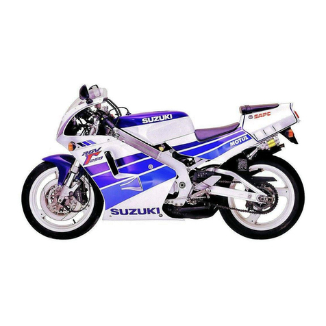
Suzuki RG250 User manual

•
~----------~
~
~
'
--
99SQ8-'286101E

FOREWORD
The
SUZUKI
RG250
has
been
developed
as
a new generation motorcycle.
It
is
packed
with highly advanced design concepts including automatic exhaust control system, a liquid
cooling system, a
G.D.
ignition system,
an
positive damping
fork
and
a full-floater
suspen-
sion system. Combined with precise control and easy handling the
RG250
provides excel-
lent
performance and outstanding riding comfort.
This service manual
has
been produced
primarily
for
experienced mechanics whose
job
is
to
inspect, adjust, repair and service
SUZUKI
motorcycles. Apprentice mechanics and
do-it-yourselfmechanics,
will
also
find
this manual
an
extremely useful guide.
Model RG250 manufactured
to
standard specifications
is
the main subject
matter
of
this manual. However, the RG250 machines distributed in
your
country
might
differ
in
minor
respects from the standard-specification and,
if
they do,
it
is
because
some
minor
modifications (which are
of
no
consequence
in
most
cases
as
far
as
servicing
is
concerned)
had
to
be made to
comply
with
the
statutory
requirements
of
your
country_
This manual contains up-to-date
information
at
the time
of
its
issue.
Latermade
modifi-
cations
and
changes
will
be
explained to each
SUZUKI
distributor
in respective markets,
to whom you
are
kindly
requested
to
make query
about
updated information,
if
any.
SUZUKI MOTOR CORPORATION
Motorcycle Technical Service Department
C:
C
OP
YRIGHT SUZUKI MOTOR CORPORATION
1990

VIEW
OF
SUZUKI
RG250
(FULL
COWLING)
RIGHT SIDE
LEFT SIDE

GROUP INDEX
GENERAL INFORMATION
PERIODIC MAINTENANCE AND
TUNE-UP PROCEDURES
"------
IENGINE
r
LCOOLING
SYSTEM
FUEL
AND
LUBRICATION
SYSTEM
ELECTRICAL
SYSTEM
CHASSIS
SERVICING INFORMATION
RG250H
(,87
-MODEL)

VIEW
OF SUZUKI
RG250
(HALF
COWLING)
RIGHT SIDE
LEFT
SIDE

GENERAL INFORMATION
,---------------
CONTENTS
-------
SERIAL NUMBER LOCATION
··
·....···
..
·
..
···············
..
····
·····
·
··
·
..
1-
1
FUEL,
OIL
AND COOLANT
RECOMMENDATION
····················
·
············
···
········
....
........
..·1- 1
BREAKING-IN
PROCEDURE
·········
··
·
·························
········
····
1-
2
CYLINDER IDENTIFICATION·············
·····························
·······
1-
2
SPECIAL
MATER
IALS
·········································
················
1-
3
PRECAUTION AND GENERAL INSTRUCTION
..
········..
············
1-
5
SPECIFICATIONS···············
··························
·· ·
······
·
···········
·1- 6

I-I GENERAL
INF
ORMATION
SERIAL
NUMBER
LOCATION
The frame
se
r
ia
l number or
V.1.
N. (Vehicle Identi-
fication
Number)
CD
is
sta
mp
ed
on
the
steering
head pipe. T
he
engine serial number @
is
locat
ed
on the
le
ft
sid
e of the cran
kcase.
T
hese
numbers
are
requir
ed
esp
e
ci
ally f
or
registering the machi
ne
and orde
ri
ng
spare part
s.
FUEL, OIL
AND
COOLANT
RECOMMENDATION
FUEL
Gasol
ine u
se
d should
be
graded 85 -95 octane in
R
es
earch
Me
thod and should
be
an
unle
ade
d or
low-lead type where they
are
available.
EN
GINE
OIL
Use
S
UZUK
I
"CC
I" o
il
or
SU
ZUKI
eel Super
oil.
Th
ey are
for
mulated
to
gi
ve
best engine per·
formance with le
ast
combustion chamber depos
it
s,
least
preignitio
n,
maximum
spark plug
lif
e a
nd
best lubrication.
If
they
are
not
available, a good
quality
T
WO-S
TRO
KE
01
L (non-
diluent
typ
e)
should be used.
TRANSMISSION
OIL
Use
a good qua
lity
S
AE
20W/40 malt
i-
grade m
otor
oi
I.
BRAKE
FLUID
Spe
ci
ficat
ion and
class
i
ficat
ion :
99000-23021
SAE
J1
703.
DO
T3
or
DD
T4
SUZU
KI Brake fluid
I
WARNING:
* Since the brake system
of
this
motorcycle
is
filled
with
a glycol-based brake
fluid
by
the manufacturer,
do
not
use
or
mix
differ
-
ent
types
of
fluid
such
as
silicone-based
and petroleum-based
fluid
for
refilling the
system, otherwise serious damage
will
result.
* Do
not
use
any brake
fluid
taken
from
old
or
used
or
unsealed containers.
* Never re-
use
brake
fluid
left
over
from
the
prevIous servicing and stored
for
a long
period.
FRONT
FORK
OIL
Us
e
th
e f
or
k oil = 10.

COOLANT
Use
an
anti-freeze & Summer coolant compatible
with
aluminum
radiator, mixed with distilled
water
only. at the ratio
of
50 : 50.
WATER FOR
MIXING
Use
distilled water
only
_ Water
other
than
distilled
wa
ter
can
corrode
and
.
dog
the aluminum radiator.
ANT1-FREEZE & SUMMER
COOLANT
The
coolant performs
as
corrosion and rust inhibi-
tor
as well as anti-freeze. Therefore,
the
coolant
should
be
used
at all times
even
though the atmos-
pheric temperature in
your
area
does
not
go
down
to
freezing point.
SUZUKI recommends the
use
of
SUZUKI GOLD-
EN
CRUISER 1 200 anti-freeze & summer coolant.
If
this
is
not
available,
use
an
equivalent which
is
compatible
with
aluminum radiator.
REQUIRED
AMOUNT
OF WATER/
COOLANT
Solution capacity (total): 1 500 ml
Water
30%
1050
ml
Coolant 450 ml
--Water
900ml
40%
Coolant 600
ml
~
-Water 750
ml
50
% -Coolant
750ml
I
CAUTION:
Mixing
of
anti-freeze & summer coolant
should be limited
to
60
%.
Mixing beyond
it
would reduce its efficiency.
If
the anti-freeze
& summer coolant mixing ratio
is
below 30
%.
rust inhibiting performance
is
greatly reduced.
Be
sure
to
mix
it
above 30%
eve
n
tho
.
ugh
the
atmospheric temperature does
not
go
down
to
freezing point.
Every new
unit
is
filled
with
anti-leakage
material, Bar
's
le
ak.
GENERAL
INFORMATION
1
-2
BREAKING-IN
PROCEDURE
During manufacture only the best possible materi-
als
are
used
and all machined parts
are
finished
to
a
ve
ry
high standard
but
it
is
still
necessary
to
allow
the moving parts
to
"BR
EAK
-IN" before subject-
ing the engine
to
maximum
stresses.
The future
performance and reliability
of
the engine depends
on the
care
and restraint exercised during its early
life. The general rul
es
are
as
follows:
•
Keep
to
these
breaking-in engine
speed
limits:
Initial 800 km Below 6 000
rlmin
Up
to
1 600 km Below 8 000 rlmin
Over 1 600 km Below
12000
rlmin
• Upon reaching
an
odometer reading
of
1600
km you
can
subject the motorcycle
to
full
throttle
operation.
However, do not exceed
12000
rlmin at any
time.
• Do
not
maintain constant engine
speed
for
an
extended time period during any portion
of
the
break-in.
Try
to
va
ry
the
throttle
position.
CYLINDER
IDENTIFICATION
The two cylinders
of
this engine
are
identified
as
left
and
right cylinder
(as
viewed by the rider on
the seat).
1-3
GENERAL I
NFORMAl
ION
SPE
CIAL
MATERIALS
The materials listed below
are
needed
for
maintenance
work
on the
RG
250, and should
be
kept on
ha
nd
for
ready
use.
They supplement such standard materials
as
cleaning fluids, lubricants, emery cloth and the
like. How
to
use
them and where
to
use
them
are
described
in
the
text
of
this manual.
Mater
ia
l Part P
age
Part P
age
~:=J
• Oil
seals
3·21 • Wheel bearings 7·14
3-33
7·45
•
Throttle
grip 7-46
• Sprocket
mounting
drum
bearing
'
il
" • Speedometer cable 7·
55
• Swing arm bearing and
dust
seal
• Tachometer cable Brake pedal shaft
'Sl-."",
.J
•
• Cushion lever bearing 7·56
SUZUKI • Steering stem bearings and races 7·33
• R
ear
shock bearing 7·
56
SUPER
GREASE
"AU • Clutch lever
and
release
99000-25010
• Side stand
• Clutch release 3
·2
7
~
.
-
~~
.
SUZUKI
MOLY
PASTE
99000
-25140 • Mating surfaces
of
upper 3·37 • Water temperature
gauge
4·10
~
and lower crankcase
- ,
.;'
-• Mechanical
seal
4- 8
~
.
SUZUKI
BOND
No. 1207B
99000
-
31140
• Brake
fluid
2-14
SUZUKI
BRAKE
FLUID
99000
·23021 (O.5L) • Oil
seal
outer
surface 3·
36
~
~
"'i
~
-
~
THREAD
L
OCK
" '
322
"
99000·
32110
~
• Gearshift shaft stopper 3·31
•
Kick
starter
gea
r retainer 3·32
bolt
=-
•
.
'--=:-
THREAD
LOCK
SUPER
"1303"
99000-32030

GENERAL
INFORMATION
1-4
Mat
e
rial
Part
Page
P.rt
p,,.
• Generator
rotor
nut
3·38
I'".
~~
~.
'-=-
THREAD
LOCK
"1324"
99000·32
1
20
• Gearshift cam guide screw 3-32
I'".
• Gearshift pawl lifter screw 3·32
~~
• Countershaft bearing-
3·39
I'\i1l
retainer
'--=-'
THREAD
LOCK SUPER
"13338" 99000-32020
•
To
prevent
leakage
of
cooling
solution
from small
hole.
SUZUKI BAR's
LEAK
99000·24240
• Cooling
solution
SUZUK
I
GOLDEN
CRUI
SER
1200
!2L)
99000·24120
• Disc
bolt
].15
I'".
7·46
}!:,q
.'
i§l§
'-=-
THREAD LOCK
"1360"
99000-32130
•
Stator
securi
ng
screws. 3·38
I'".
6-
5
~~
•
Front
fork
damper rod
bolt
7-27
I'Th1§
• Reed
valve
3·22
--
THREAD
LOCK
"1342"
99000-32050

1-5
GENERAL
INFORMATION
PRECAUTION
AND
GENERAL
INSTRUCTION
Observe
the
following items
without
fail when disassembling
and
reassembling motorcycles.
o
Be
sure
to
repl
ace
packings, gaskets, circlips, 0 rings and coner pins
with
new ones.
CAUTION
: 1
Never
reuse
a circlip after a circlip h
as
been
removed from a shaft, it should
be
discarded a
nd
a
ne
w
c
ir
clip must be
in
stalled.
When installing a new circlip. care
must
be taken
not
to
expand
the
end gap larger
tha
n required to
slip the circlip over
th
e shaft.
After installing a
ci
rclip. always insure
that
it
is
completely seated
in
its groove and securely fitted.
o Tighten cy
li
nder
head
and
case bolts
and
nuts beginning with larger
diameter
and
ending with smaller
diameter. and from
ins
i
de
to
out
-side diagonally,
to
the specified tightening torque.
o
Use
special
too
ls where specified.
o
Use
genuine parts and recommended oils.
o
When
2
or
more persons
work
together, pay attention
to
the safety
of
each
other.
o
After
the reassembly, check parts for tightness
and
operation.
o Treat
gaso
li
ne,
which is extremely flammable
and
highly explosive, with greatest
care.
Never
use
gasol
ine
as
cleaning solvent.
Warnin
g,
Caution and Note
are
included in this manual occasionally, describing the following contents.
WARNING
..................
The
personal
safety
of
the
rider
or
bystanders
may
be
involved
. Disregarding
th
is
information
could result in personal
injury
.
CAUTION
.....
...
...
........
These instructions point
out
special service procedures
or
precautions
th
at must
be
followed
to
avoid
damaging
the
machine
.
NOTE
....
........
......
.......
This
provides
special
information
to
make
maintenance
easier or i
mpo
r
tant
in·
structions
clearer.
REPLACEMENT PARTS
When
you
replace any parts, use
only
genuine
SUZUKI r
eplacement
par
ts,
or
their
equivalent.
Genuine SUZU
KI
par
ts
are
high
qual
ity
parts
whic
h are de
Si
gned
an
d bui
lt
specifically
for
SUZUKI vehicles.
C
AUTION
:
USB
of
replac
ement
parts
which
are
not
equiv
a-
lent
in
qua
li
ty
to
genuine SUZUKI
parts
can lead
to
performa
nce pro
bl
e
ms
and
da
mage
.

SPE
CIFICATIONS
DI
MENSIONS
AND
DRY
MASS
Overall length
.........................
.
Overall width
......
..
.........
.
.......
.
Overall height
..........••.
.
.•..........
2010
mm
675
mm
1 175 mm
Wheelbase. . . . . . . . . . . . • . . . . . . . . . . . . . .
..
, 355 mm
GENERAL
INFORMATION
1·6
Ground clearance 150
mm
..... Half cowling
130
mm
..... Full cowling
Dry
mass
...........•.....
• . • .
.•
··
• .
··
128
kg
..... Half cowling
ENGINE
Typ
e
................................
.
Number of cylinders
.....•.
.•
.
..
. .
.......
Bore
....................
•
........
.
...
Stroke
........
.
.....
..
....
..
..
. . .
...
.
Piston displacement
.......
..
...........
.
Compression ratio
.... ....
. •
..
.
.•.•.
.
...
Ca
rburet
or .
..
...
.
.......
. .
...
.
.......
.
130
kg
..... Full cowling
Two-strok
e,
water-coo
le
d
2
54.0 mm
54.0
mm
247
cm3
7.0:
1
MI
KUNI
VM28SS,
twin
Air cleaner
.......
.
..
.
...........
.
.....
Po
lyurethane
f
oam
element
Starter
system
..........
......
.
.......
.
Lubrication system
....
• .
..
..
. .
..........
TRANSMISSION
Prim
ar
y kick
SUZUKI
"CCI"
Clutch .
..
......
.
.....•
..
. •
,.
. .
..
. .
....
Wet multi-plate
type
Transmission
.............
.
....
• .
......
6-speed
constant
mesh
Gearshift
pattern
......•...•.•.
. •
~
• .
....
l -
down,
Soup
Pri
ma
ry r
eductio
n
.........•.
....
•
......
3.00
0
(72/2
4)
Final r
educ
tion
............•............
2.785
(39/
14
)
Gear ratio
s,
Low
.,
..
.
..................
2.23
0 (
29
/13)
2nd
.....
"
...
. ,
....
.
.....
. . 1.562
(2
5/16)
3rd
........................
1.210 (23/19)
4th
....
..
..........
.
....
..
. 1.000 (21/21)
5th
.....
,
•...............
. . 0.863 (19
122)
Top
.......
,
..
,.....
.
....
0.782 (18/23)
Drive chain
...............
• .
...
.
.......
DA
IDO·
DID520V
·S
or
TAKASAGO
RK520SMO·Z2,
110li
nks

I·)
GENERAL
INFORMATION
CHASSIS
Front
suspension
POSt
damp
fork
system, telescopic, pneumatic
/co
il
spring oil damped, spring preload
fully
adjustable,
damping force 4-
way
adjustable
Rear suspension
..........
•
•.
....•.....
, Full-floating suspension system, pneumatic/coil
spring, oil damped
Steering angle
...............
...•.......
30
D (right & left)
Caster
........
.
..•....
..
•.
....
•
•.•.
...
64°
25'
Trail
.........
. . . • • . • • . . • . . . . . . • . . . .
..
103
mm
Turning radius
...........
•
.............
3.1
m
F
ront
brake
......•
• • •
..
...
••
• .
•••
.....
Disc brake
Rear brake
........
_
....
..............
.
Fr
ont
tire size
...................
•••
....
Rear tire size
..........
...
...
...
..
....
.
Front
fork
stroke
.........•
•.
.....
,
....
.
Rear wheel travel
.....••
••••
.•
••.••
.....
Front
tire
pressure
.........•............
Rear tire pressure
........
. . •
.••
••
.•
, '
...
ELECTRICAL
Di
sc brake
100/90 H
16
110/80 H18
130 mm
125
mm
200
kPa
(2.00
kg
/e
m' I
(Normal solo riding)
225
kPa
(2.25
kg
/em'
I
(Normal solo riding)
Ignition type
......
••.
......••
• .
.•
.....
SUZUKI
"PEl"
Ignition
timing
.....•......•
. , . ,
..
•.
...
, 150 B.T.D.C,
at
6
000
r/min
Spark plug
.............
.
...
..
.........
NGK 89ES
.....
E-
01
.
24. 25,
30
NGK
BR9ES,
...
The others
Battery
............•....
,
••...
..•
•
....
12V
18.0
kC
(5
Ahl/10
HR
Gene
rator
.....••
•••
•.
. .
•.•••..•.••...
. Three-phase
A.Co
generator
Fuse
..............
•
.............•.
.
..
20A
CAPACITIES
Fuel tank including
reserve
......
0
••
• 0 0 " •
17
L
Reserve
...
0
••••••••
, • ,
••
0
•••••
4
.7
L
Engine
oil
0
••
•••
•••••••••••
0
•••
• • • • • 0 • 0 1.2 L
Transmission oil
....
. .
...
.........
0
•••••
850 ml
Fork
oil
..........
•..
• •
..
•.•....•..
...
346 ml
Cooling solution
.....•...........
.•.
0
•••
1 500 ml
...
Th
ese
specifications
are
subject
to
change wi
thout
notice.

PERIODIC MAINTENANCE AND
TUNE-UP PROCEDURES
,---------------
CONTENTS
------------
----,
PERIODIC MAINTENANCE SCHEDULE·····..··..····.. ·· ·· ·..······· ···2- 1
PERIODIC MAINTENANCE AND
TUNE-
UP
PROCEDURES
·····················
··· ·
···················
····
····2- 3
BATTERy
····································
····
········
·····
··············
2-
3
ENGINE BOLTS AND
NUTS····
···········
······
··
·········
··········
2-
4
CYLINDER HEAD, CYLINDER AND
MUFFLER
.. ··
··············
2- 5
SPARK
PLUG
··
·········
··
·············
····
··········
···
·······
··
····
···· ·2- 5
AIR CLEANER .. ·········
·············
···
··················
····
······
·· ···2- 6 ,
CARBURETOR
··········
·
·············
··
················
·····
··
······
·· ··
2-
7
RADIATOR HOSE
...............
.....
.................
.
...............
.·
2-
9
COOLANT ....·······
··
..
·..
··
..
·· ·· ··
..
·....
··
..
······..
··
..···
..
·····....
2-
9
FUEL
LINE·
................................................................
2-10
CLUTCH·····
··········
········
·········
········
·················
..
·········
2-10
OIL
PUMp·····
··
··
..
···....···
..........
····.. ·......···
..
··
..
··
......·····2-10
TRANSMISSION
OIL
....
..
....
........................
..
...............
2-11
DRIVE CHAIN·····
..
··
..
·····
..
··
..
···......···
..
·....·
..
··
..
··
..
··
..
··
···2-
12
BRAKES
··········
·
············
.. ···
·····
····
·············
··············· ···
2-14
STEERING..
········
·....·.. ··.. ·· ..
····
..
·
......
·· ....·.. ·· .. ·· .. ··
..
··"'
2-
17
FRONT FORK
..
·······
..
··
..
·..·.....
...............
..
....................
2-17
REAR SUSPENSION
········
············
··············
·················2-18
TIRES
···························
······
······
..
···························
···
2-19
CHASSIS
BOLT
AND NUTS
......
....
........
.... ....·
..............
·
2-19

2-
1
PERIODIC
MAINT
ENANCE
AND
TUNE-UP
PROCEDURES
PERIODIC
MAINTENANCE
SCHDULE
The chart below lists the recommended intervals for
al
l the requi
red
periodic service work
necessary
to
keep
the
motorcycle operating
at
peak
performance
and ec
onom
y. Traveli
ng
distances are expressed
in
term
of
kilometers or mil
es.
NOTE
:
Vehicles operated
under
severe
conditions
may required
more
frequent
servicing.
~
km
1000
6000
12000 18000
24000
miles
600
4000
7500
11000
15000
Item
months 2 12
24
36
48
Batter
y -I I I I
Engine
bolts
and
nut
s T T T T T
Cylinder
head
, cylinder
and
muffler
-C C C C
Spark
plug I R R R R
Air
cleaner Clean ev
ery
3
000
km
Carburetor I I I I I
I -I -I
Radiator
hose Replace every 4 years
Coolant Change every 2 years
I I I I I I I
Fuel line Replace very 4 yea
rs
Clutch I I I I I
Oil
pump
I I I I I
Tr
ansmission
oil
R -R -R
I I I I I
Drive
chain Clean and lubricate every 1
000
km
Brake I I I I I
I I I I I
Brake hose Replace every 4 years
Brake fluid . Replace very 2 years
Steering I I I I I I
- - I I -I
Fr
ont
fork Inspect air pressure v
ery
6
months
Rear suspension --I -I
I-
Tires I I I I I I
Chassis
bo
l
ts
and
n
ut
s T I T T T T
NOTE: C = Cl
ean
. I
"'"
Inspect. R = Replace, T
""
Tighten

PERIODIC
MAINTENANCE
AND
TUNE-UP
PROCEDURES
2-2
L
UBRICATION
POINTS
Proper lubrication
is
important for smooth operation and long life
of
each
working part
of
your
motorcycle
and
also for safe riding.
It
is
a good practice
to
lubricate
the
machine
after
along rough ride
and
after
getting
It
wet in the rain
or
after washing it. Major lubrication points
are
indicated below.
(!]
..
Motor
oil
t!J
._.
Grease
Throttle
grip
Rear
suspension
pivots
r
1:,
"m
pi,ot
t!I Rear brake link pivots
[!]
10luIOh
lever
holder
'~:~~~:~:.~
;::::~~cable
I:!
gear box
Brake lever holder
,
stem bearing

2·3
PERIODIC
MAINTENANCE
AND
TUNE·UP
PROCEDURES
PERIODIC
MAINTENANCE
AND
TUNE-UP
PROCEDURES
This section describes
the
servicing procedures for
each
item
of
the Periodic Maintenance require-
ments.
BATTERY
Inspect
6000
km,
12000
km,
18000
km,
24000
km,
14000
miles, 7
500
miles,
11
000
miles 15 000 miles)
The battery
must
be removed
to
check the electro-
lyte level and specific gravity.
• Remove
the
seat and right frame cover.
• Remove
the
battery
e
and
Ef)
leads
at
the
battery terminals.
• Remove
the
battery
from
the
frame.
• Check
the
electrolyte
for level
and
specific
gravity. Add distilled
water
as necessary, to
keep
the
surface of the electrolyte above the
MIN
level line
but
not
above the
MAX
level
line.
For
chec
king
sp
ecific gravity, use a
hydrometer
to
determine
the
charged
condition
.
09900
·28
403
Standard specif
ic
gravity
Hydrom
eter
An
S.G. reading
of
1.22 (
at
20
°
C)
or
under
means
that
the
battery
needs recharging
off
the
machine;
take
it
off
and
charge
it
from a recharger. Charging
the
battery
in
place can lead
to
failure of
the
regu
la
tor/rectifier.
•
To
install
the
battery.
reverse
the
procedure
described above.
CAUTION
:
When installing
the
battery
lead wires, fix
the
ltl lead first and e lead last.
• Make sure
that
the
battery
breather pipe
is
tightly secured
to
the
battery
and
is
in
good
c
ondition.
Also confirm
that
it
is
routed
as
shown
in the figure.
I
Battery
~
..
- Breather pipe
\,
x:
~"".
Clamp

PERIODIC
MAINTENANCE
AND
TUNE-UP
PROCEDURES
2-4
ENGINE BOLTS
AND
NUTS
Tighten 1 000 km, 6 000 km, 12 000 km,
18 000 km,
24
000 km, 1600 mile
s,
4 000
mi
l
es,
7500
miles
,
"000
miles, 15 000
m
il
es)
CY
LINDER
HEAD
NUT
S
AN
D
CY
LI
NDER
NU
TS
• Remove the
seat
and frame covers (right
and
leftl.
• Remove the fuel tank (Refer
to
papge 3-2)
• Remove the middle
and
lower cowling (Refer
to
page
7-2)
• Remove the radiator (Refer to
page
.4.3)
• Tighten the cylinder head bolts and nuts to the
spec
ified torque with a torque wrench
sequen
-
tially
in
ascending numerical order with the
engine
cold.
Bmm
23 -
27
N-m
Tightening 12.3 -
2.7
kg-ml
torque
6mm
9-11N'm
10.9 -
1.1
kg-ml
• Tighten the cylinder nuts to
the
specified torque.
Tighteni
ng
torque 6 - 9
N'm
10
.6 - 0.9 kg-
mJ
EX
HAUST PIPE
NUT
S
• Tighten the exhaust pipe nuts to the specified
torque.
Tightening torque
lB
-
2BN'm
I1.B -
2.B
k9
-ml
\
!

2-
5 PERI
OOIC
MA
INTENANCE
ANO
T
UN
E-
UP
PROCEOURES
CYLINDER
HEAD,
CYLINDER
AND
MUFFLER
Clean
6000
km,
12000
km,
18000
km,
24000
km
(4000
miles,
7500
miles,
11
000
miles,
15000
miles).
• C
arb
on
deposits in the
co
mbu
stion
chamber
of
the cylin
de
r h
ea
d and at
th
e p
is
ton crown
will
raise
the
co
mpr
ession ratio and
may
cause
pre
-
ig
n
it
ion or over
he
at
ing.
•
Ca
rbon d
ep
osited at
th
e
exhaust
port
of
the
cylin
der
wi
ll pr
event
r
ed
ucing the
out
put.
periodically.
SPARK
PLUG
the
flow
of
exhaust
gas,
Remove
carbon
deposits
Inspect 1 000 km (600 mile
sl
Replace
6000
km,
12000
km, 18 000 km,
24000
km, (
4000
mi
le
s,
7 500 mi
le
s,
11 000
miles, 15 000 miles)
Neglecting
the
spark pl
ug
eventually leads
to
difficult
starting
and
poo
r per
formance
.
If
the
spa
rk plug
is
used
for
a long
pe
riod, the electrode
gradually burns away and carbon builds up along
the
inside
part.
In
ac
cor
d
ance
with t
he
Peri
odic
Maintenance
Chart
,
the
spark pl
ug
should
be
in-
spected
or
rep
l
aced
.
• Carbon deposits
on
the spa
rk
pl
ug
will pre
ve
nt
good sparking and
cause
mis
firin
g.
Cle
an the
de
posi
ts
off
pe
riodically.
•
If
the center electrode
is
fairly
worn down, the
plug should
be
replaced. If scheduled, the plug
gap
s
ets
to th
e proper gap.
09900-20803 Thickness
gauge
Spa
rk pl
ug
gap
0.6 - 0.8 mm
~
..
'\
.....
..
"·t
IJ
t_
i t -
, "
•.
..
a
••
••a
••
~
ts~;:
~~
0.6 -o.S
mm

PERIODIC
MA
I
NTENANCE
AND
TUNE-UP
PROCEDURES
2-6
• Ch
ec
k spark plug
for
burnt condition.
If
abnor-
mal, replace the plug
as
indicated right.
NOTE:
"
Roo
type spark plug
fitted
under
some
of
specifications and
it
means
that
the
resistor
is
located
at
the
center
electrode
to
prevent
radionoise.
NOTE:
To
check
the
spark plugs, first make sure
that
the fuel tank contains unleaded gasoline, and
after
a test ride
if
the
plugs are either sooty
with carbon
or
burnt
white, replace them
altogether.
NOTE:
Confirm
the
thread size and reach when
replacing
the
plug.
If
the
reach
is
too
short
,
carbon will be deposited
on
the
screw
portion
of
the
plug hole and engine damage may
result.
AIR
CLEANER
: Clean Every 3
000
km
If
the air cleaner
is
clogged with dust, intake resis-
tance
will
be increased with a resultant decrease
in
power
output
and an increase
in
fuel consump-
tion.
Check and clean
the
element
in
the following
manner.
• Remove
the
right and left frame covers.
• Loosen
the
fuel tank securing bolts and
then
li
h
up
rear side.
• Remove the screw and take
out
the air cleaner
case cover.
• Remove a screw and take
out
the air cleaner
ele
ment
from the cleaner case.
• Separate the polyurethane foam
element
from
the eleme
nt
frame.
For E-01,
24
,
25,
30
NGK
REMARKS
If
the standard plug
is
apt
BSES
to
get wet, replace
with
this plug. Hot type.
B9ES Standard
For E-02, 06,
15,16,21
,39
NGK
REMARKS
If
the
standard plug
is
apt
BRSES
to
get wet, replace with
this plug. Hot type.
SR9ES
Standard
,
Table of contents
Other Suzuki Motorcycle manuals

Suzuki
Suzuki drz 400E User manual

Suzuki
Suzuki sv1000S User manual

Suzuki
Suzuki GSX-R600 User manual

Suzuki
Suzuki SV650 Manual

Suzuki
Suzuki 2007 SV650K7 Manual

Suzuki
Suzuki k8 gsx1300r Reference manual

Suzuki
Suzuki FA50 User manual

Suzuki
Suzuki DL1000 User manual

Suzuki
Suzuki VZR1800 2007 User manual

Suzuki
Suzuki DR-Z400S 2001 User manual

Suzuki
Suzuki 1996 GSX-R750 User manual

Suzuki
Suzuki GSX1400 User manual

Suzuki
Suzuki DL650K5 User manual

Suzuki
Suzuki RM85/LK5 User guide

Suzuki
Suzuki GS550 User manual

Suzuki
Suzuki RM-Z250L9 User guide

Suzuki
Suzuki GSX 600F 2000 User manual

Suzuki
Suzuki GSX650FA User manual

Suzuki
Suzuki Intruder 1978 User manual

Suzuki
Suzuki DR350 User manual