Suzuki GSX-R1000 User manual

FOREWORD GROUP INDEX
COOLING
AND
LUBRICATION
SYSTEM
FUEL SYSTEM
AND
THROTTLE
BODY
EMISSION CONTROL
INFORMATION
~----.
B
===================
___
B
~-_.
IPERIODIC MAINTENANCE
IGENERAL INFORMATlON
IFI SYSTEM DIAGNOSIS
IENGINE
IEXHAUSTSYSTEM
ICHASSIS
IELECTRICAL SYSTEM
IWIRING DIAGRAM
ISERVICING INFORMATlON
*This manual has been prepared on the basis
of
the latest specifications at the time of publi-
cation.
If
modifications have been made since
then, differences
may
exist between the con-
tent
of
this manual and the actualmotorcycle.
*Illustrations in this manual are used to show
the basic principles
of
operation
and
work
procedures. They may not represent the
actual motorcycle exactly in detail.
*This manual is written for persons who have
enough knowledge, skills and tools, including
special tools, for servicing SUZUKI motorcy-
cles.
If
you do not have the properknowledge
and
tools, ask
your
authorized SUZUKI
motorcycle dealer to help you.
Inexperienced mechanics or mechanics
without the proper tools and equipment
may not be able to properly perform the
services described in this manual.
Improper repair may result in injury to the
mechanic and may render the motorcycle
unsafe for the rider and passenger.
AWARNING
This manual contains an introductory description on
the SUZUKI GSX-R1000 and procedures for its
inspection/service
and
overhaul
of
its main compo-
nents.
Other information considered as generally known is
not included.
Read the GENERAL INFORMATION section to
familiarize yourselfwith the motorcycle and its main-
tenance. Use this section as well as other sections
to use as a guide for proper inspection and service.
This manual will help you know the motorcycle bet-
ter so that you can assure your customers
of
fast
and reliable service.
~
I
SUZUKI MOTOR CORPORATION
©COPYRIGHT SUZUKI MOTOR CORPORATION 2003

HOW TO USE THIS MANUAL
TO LOCATE WHAT YOU ARE LOOKING FOR:
1. The text of this manual is divided into sections.
2. The section titles are listed in the GROUP INDEX.
3. Holding the manual as shown at the right will allow you to find
the first page of the section easily.
4. The contents are listed on the first page of each section to
help you find the item and page you need.
\\
\,---
COMPONENT PARTS AND WORK TO BE DONE
Under the name of each system or unit, is its exploded view. Work instructions and other service information
such as the tightening torque, lubricating points and locking agent points, are provided.
Example: Front wheel
CD
Brake disc
~
Dust seal
@Bearing
@Spacer
@Spacer nut
@Front wheel
®Front axle
®Brake disc bolt (Front)
--
r!J
-
ITEM N·m kgf-m
Ib-ft
®100 10.0 72.5
~
®23 2.3 16.5

SYMBOL
Listed in the table below are the symbols indicating instructions and other information necessary for servic-
ing. The meaning of each symbol is also included in the table.
SYMBOL DEFINITION SYMBOL DEFINITION
~
Torque control required. •Apply THREAD LOCK SUPER "1360".
Data beside it indicates specified 99000-32130
torque.
l!r
Apply oil. Use engine oil unless other- eUse engine coolant.
wise specified.
lIr Apply molybdenum oil solution. eUse fork oil.
(Mixture of engine oil and SUZUKI 99000-99044-LO1
MOLY
PASTE in a ratio of 1:1)
~
Apply SUZUKI SUPER GREASE "A". I
99000-25010 (Others) Apply or use brake fluid.
99000-25030 (USA)
~
Apply SUZUKI
MOLY
PASTE.
~
Measure in voltage range.
99000-25140
€i]J
Apply SUZUKI BOND "1215".
~
Measure in current range.
99000-31110 (Except USA)
-41207~
Apply SUZUKI BOND "1207B".
~
Measure in resistance range.
99104-31140 (USA)
-41207~
Apply SUZUKI BOND "1207B".
~
Measure in diode test range.
99000-31140 (Except USA)
~
Apply THREAD
LOCK
SUPER "1303".
~
Measure in continuity test range.
99000-32030
•Apply THREAD LOCK SUPER "1322".
l+ooLI
Use special tool.
99000-32110 (Except USA)
•Apply THREAD LOCK "1342". -Indication of service data.
99000-32050 (USA)

ABBREVIATIONS USED IN THIS
MANUAL
AABDC : After Bottom Dead Center
AC : Alternating Current
ACL : Air Cleaner, Air Cleaner Box
API : American Petroleum Institute
ATDC : After Top Dead Center
ATM Pressure: Atmospheric Pressure
:Atmospheric Pressure sensor
(APS, AP Sensor)
A/F : Air Fuel Mixture
EECM : Engine Control Module
Engine Control Unit (ECU)
(FI Control Unit)
ECT Sensor : Engine Coolant Temperature
Sensor (ECTS), Water Temp.
Sensor (WTS)
EVAP : Evaporative Emission
EVAP Canister: Evaporative Emission
Canister (Canister)
EXC System : Exhaust Control System (EXCS)
EXC Valve : Exhaust Control Valve (EXCV)
EXCV Actuator: Exhaust Control Valve Actuator
(EXCVA)
BBBDC
BTDC
B+
CCKP Sensor
CKT
CLP Switch
CMP Sensor
CO
CPU
DDC
DMC
DOHC
DRL
: Before Bottom Dead Center
: Before Top Dead Center
: Battery Positive Voltage
:Crankshaft Position Sensor
(CKPS)
:Circuit
: Clutch Lever Position Switch
(Clutch Switch)
:Camshaft Position Sensor
(CMPS)
: Carbon Monoxide
: Central Processing Unit
: Direct Current
: Dealer Mode Coupler
: Double Over Head Camshaft
: Daytime Running Light
FFI
FP
FPR
FP Relay
GGEN
GND
GP Switch
HHC
IlAP Sensor
IAT Sensor
IG
LLCD
LED
LH
: Fuel Injection, Fuel Injector
: Fuel Pump
: Fuel Pressure Regulator
: Fuel Pump Relay
:Generator
: Ground
:Gear Position Switch
:Hydrocarbons
: Intake Air Pressure Sensor (lAPS)
: Intake Air Temperature Sensor
(lATS)
: Ignition
: Liquid Crystal Display
: Light Emitting Diode
(Malfunction Indicator Lamp)
: Left Hand

M
MAL-Code
Max
MIL
Min
NNOX
oOHC
OPS
pPCV
RRH
ROM
SSAE
STC System
STP Sensor
ST Valve
STV Actuator
TTO Sensor
TP Sensor
TPC Valve
:Malfunction Code
(Diagnostic Code)
:Maximum
:Malfunction Indicator Lamp
(LED)
: Minimum
:Nitrogen Oxides
: Over Head Camshaft
: Oil Pressure Switch
: Positive Crankcase
Ventilation (Crankcase Breather)
: Right Hand
: Read Only Memory
:Society of Automotive Engineers
:Secondary Throttle Control System
(STCS)
:Secondary Throttle Position Sensor
(STPS)
:Secondary Throttle Valve (STV)
:Secondary Throttle Valve Actuator
(STVA)
: Tip Over Sensor (TOS)
:Throttle Position Sensor (TPS)
: Tank Pressure Control Valve (TPCV)

SAE-TO-FORMER SUZUKI TERM
This table lists SAE (Society of Automotive Engineers) J1930 terms and abbreviations which may be used in
this manual in compliance with SAE recommendations, as well as their former SUZUKI names.
SAE TERM
FORMER
SUZUKI
TERM
FULL TERM ABBREVIATION
A
Air Cleaner
ACl
Air Cleaner, Air Cleaner Box
B
Barometric Pressure BARO Barometric Pressure, Atmospheric
Pressure (APS, AP Sensor)
Battery Positive Voltage B+ Battery Voltage, +B
C
Camshaft Position Sensor CMP Sensor Camshaft Position Sensor (CMPS)
Crankshaft Position Sensor CKP Sensor Crankshaft Position Sensor (CKPS),
Crank Angle
D
Data Link Connector
DlC
Dealer Mode Coupler
Diagnostic Test Mode DTM -
Diagnostic Trouble Code DTC Diagnostic Code, Malfunction Code
E
Electronic Ignition EI -
Engine Control Module ECM Engine Control Module (ECM)
FI Control Unit, Engine Control Unit (ECU)
Engine Coolant
level
ECl
Coolant
level
Engine Coolant Temperature ECT Coolant Temperature, Engine Coolant Tem-
perature
Water Temperature
Engine Speed RPM Engine Speed (RPM)
Evaporative Emission EVAP Evaporative Emission
Evaporative Emission Canister EVAP Canister - (Canister)
Exhaust Control System EXCS EXC System (EXCS)
Exhaust Control Valve EXCV EXC Valve (EXCV)
Exhaust Control Valve Actuator EXCVA EXCV Actuator (EXCVA)
F
Fan Control FC -
Fuel
level
Sensor -Fuel
level
Sensor, Fuel
level
Gauge
Fuel Pump FP Fuel Pump (FP)

SAE TERM FORMER SUZUKI TERM
FULL TERM ABBREVIATION
G
Generator GEN Generator
Ground GND Ground (GND, GRD)
I
Idle Speed Control ISC -
Ignition Control IC Electronic Spark Advance (ESA)
Ignition Control Module ICM -
Intake Air Temperature IAT Intake Air Temperature (IAT), Air Temperature
MI
Malfunction Indicator Lamp MIL LED Lamp
Malfunction Indicator Lamp (MIL)
Manifold Absolute Pressure MAP Intake Air Pressure (lAP), Intake Vacuum
Mass Air Flow MAF Air Flow
a
On-Board Diagnostic OBD Self-Diagnosis Function
Diagnostic
Open Loop OL -
P
Programmable Read Only Memory PROM -
Pulsed Secondary Air Injection PAIR Pulse Air Control (PAIR)
Purge Valve Purge Valve Purge Valve (SP Valve)
R
Random Access Memory RAM -
Read Only Memory ROM ROM
S
Secondary Air Injection AIR -
Secondary Throttle Control System STCS STC System (STCS)
Secondary Throttle Valve STV ST Valve (STV)
Secondary Throttle Valve Actuator STVA STV Actuator (STVA)
T
Throttle Body TB Throttle Body (TB)
Throttle Body Fuel Injection TBI Throttle Body Fuel Injection (TBI)
Throttle Position Sensor TP Sensor TP Sensor (TPS)
Tank Pressure Control Valve TPC Valve TPC Valve (TPCV)
V
Voltage Regulator VR Voltage Regulator
Volume Air Flow VAF Air Flow

WIRE COLOR
B : Black Gr : Gray R : Red
BI : Blue Lbl : Light blue W : White
Br : Brown Lg : Light green Y : Yellow
Dg : Dark green 0:Orange
G: Green P : Pink
BIBI
BIG
BIR
BN
BI/G
BI/W
GIB
G/W
GrlB
Gr/W
OIB
OIR
ON
P/w
RIBI
WIB
WIR
YIBI
YIR
: Black with Blue tracer
: Black with Green tracer
: Black with Red tracer
: Black with Yellow tracer
: Blue with Green tracer
: Blue with White tracer
: Green with Black tracer
: Green with White tracer
:Gray with Black tracer
:Gray with White tracer
:Orange with Black tracer
:Orange with Red tracer
:Orange with Yellow tracer
: Pink with White tracer
: Red with Blue tracer
: White with Black tracer
: White with Red tracer
:Yellow with Blue tracer
:Yellow with Red tracer
BIBr
B/Lg
B/W
BIIB
BIIR
BIN
GIBI
GN
GrlR
GrN
OIG
O/w
PIB
RIB
R/W
WIBI
YIB
YIG
Y/w
: Black with Brown tracer
: Black with Light green tracer
: Black with White tracer
: Blue with Black tracer
: Blue with Red tracer
: Blue with Yellow tracer
: Green with Blue tracer
: Green with Yellow tracer
: Gray with Red tracer
: Gray with Yellow tracer
:Orange with Green tracer
:Orange with White tracer
: Pink with Black tracer
: Red with Black tracer
: Red with White tracer
: White with Blue tracer
:Yellow with Black tracer
:Yellow with Green tracer
:Yellow with White tracer

GENERAL
INFORMATION
1·1
I
GENERALWFORMATION
CONTENTS
WARNING/CAUTION/NOTE 1- 2
GENERAL PRECAUTIONS.....................................................................•.....1- 2
SUZUKI GSX-R1000K3 ('03-MODEL) .......................•..................................1- 4
SERIAL NUMBER LOCATION............•.........................................................1- 4
FUEL, OIL
AND
ENGINE COOLANTRECOMMENDATlON.........••.............1- 5
FUEL (FOR USA
AND
CANADA)...................................................•.......1- 5
FUEL (FOR OTHER COUNTRIES)••................•.................................•..•.1- 5
ENGINE OIL (FOR USA)...........................•.............................................1- 5
ENGINE OIL (FOR OTHER COUNTRIES) .....................•..•....................1- 5
BRAKE
FLUiD•...........................•....................•..................................•....1- 5
FRONT
FORK
OIL ..........................................•.......................................1- 6
ENGINE
COOLANT
..........•...........................•.......................•.................1- 6
WATER FOR MIXING ....................•..........................•.............................1- 6
ANTI-FREEZE/ENGINE
COOLANT
..........•.............................................1- 6
LIQUID
AMOUNT
OF WATER/ENGINE
COOLANT
.........................•....1- 6
BREAK-IN PROCEDURES 1- 7
CYLINDER IDENTIFICATION....................................................................•..1- 7
INFORMATION
LABELS
...........................................................•...................1- 8
SPECIFICATIONS......................................•..........•.......................•...............1- 9
DIMENSIONS
AND
DRY
MASS 1- 9
ENGINE..........................................••........................................•........•.....1- 9
DRIVE TRAIN ...................•.................••.......................•.........•......•...•......1- 9
CHASSiS.................••...................•.•...............•..................•......•.......••.•...1-10
ELECTRICAL.............................................................•.................•..........1-10
CAPACiTIES 1-10
COUNTRY
AND
AREA
CODES....................•................•..............................1-11
•

1-2
GENERAL
INFORMATION
WARNING/CAUTION/NOTE
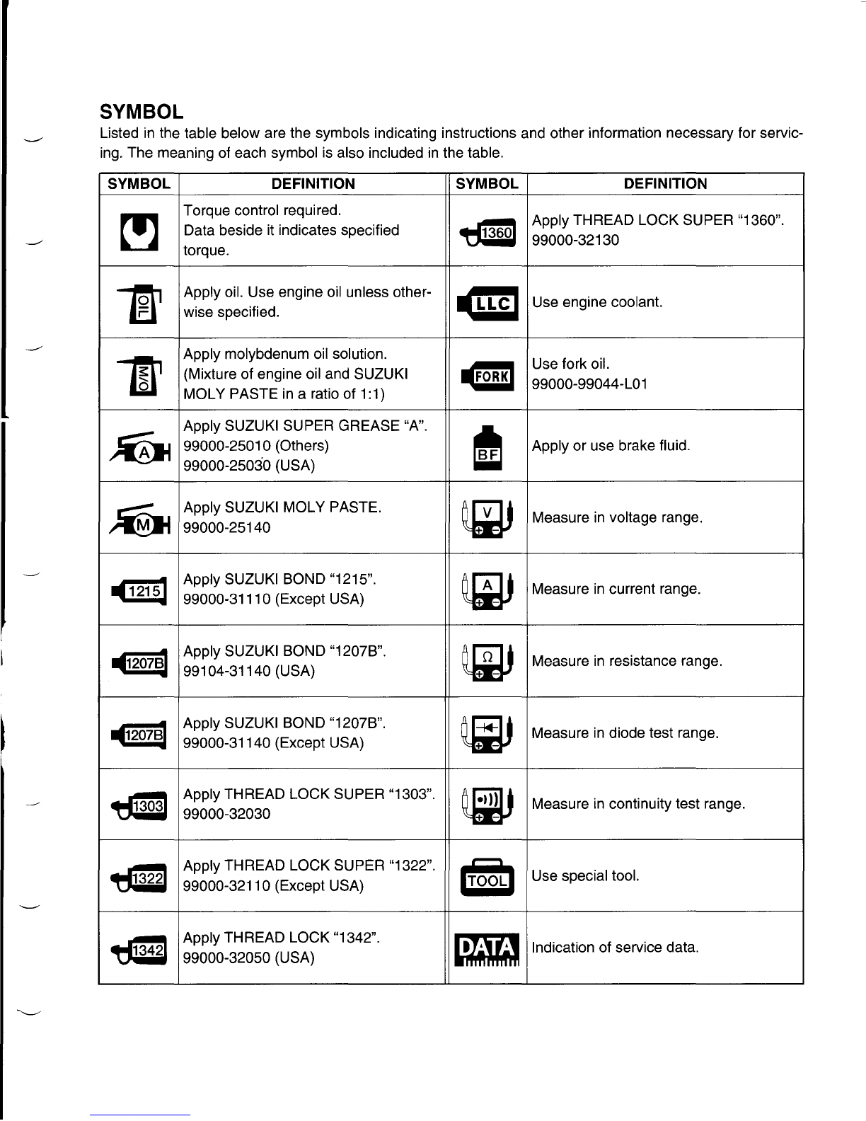
Please read this manual and follow its instructions carefully. To emphasize special information, the symbol
and the words WARNING, CAUTION and NOTE have special meanings. Pay special attention to the mes-
sages highlighted by these signal words.
AWARNING
Indicates apotential hazard
that
could
result in death or injury.
ICAUTION I
Indicates apotential hazard that
could
result in motorcycle damage.
NOTE:
Indicates special information to make maintenance easieror instructions clearer.
Please note, however, that the warnings and cautions contained in this manual cannot possibly cover all
potential hazards relating to the servicing, or lack of servicing, of the motorcycle. In addition to the WARN-
INGS and CAUTIONS stated, you must use good judgement and basic mechanical safety principles. If you
are unsure about how to perform a particular service operation, ask a more experienced mechanic for
advice.
GENERAL PRECAUTIONS
AWARNING
*Proper service and repair procedures are important
for
the safety of the service mechanic and
the safety and reliability of the motorcycle.
*When 2 or more persons
work
together, pay attention to the safety of each other.
*When it is necessary to run
the
engine indoors, make
sure
that exhaust gas in forced
out-
doors.
*When
working
with
toxic
or flammable materials, make sure that
the
area
you
work
in is well-
ventilated and
that
you
follow
all
of
the material manufacturer's instructions.
*Never use gasoline as a cleaning solvent.
*To avoid getting burned, do
not
touch
the engine, engine oil, radiator and exhaust system
until
they
have cooled.
After servicing
the
fuel, oil, water, exhaust or brake systems, check all lines and
fittings
related
to the system
for
leaks.

GENERAL
INFORMATION
1·3
!CAUTIONI
*If parts replacement is necessary, replace the parts
with
Suzuki Genuine Parts or their equiva-
lent.
*When removing parts that are to be reused, keep them arranged in an orderly manner so that
they
may be reinstalled in the proper order and orientation.
*Be sure to use special
tools
when instructed.
*Make sure that all parts used in reassembly are clean. Lubricate them when specified.
*Use the specified lubricant, bond, or sealant.
*When removing
the
battery,
disconnect
the
negative cable
first
and then the positive cable.
*When reconnecting the battery, connect
the
positive cable
first
and then the negative cable,
and replace the terminal cover on
the
positive terminal.
*When performing service to electrical parts, if the service procedures
not
require use
of
bat-
tery power,
disconnect
the negative cable the battery.
*When tightening the
cylinder
head and case
bolts
and nuts, tighten the larger sizes first.
Always tighten the
bolts
and nuts diagonally from
the
inside toward outside and to the speci-
fied tightening torque.
*Whenever you remove oil seals, gaskets, packing, O-rings,
locking
washers, self-locking
nuts, cotter pins,
circlips
and certain other parts as specified, be sure to replace them with
new ones. Also, before installing these new parts, be sure to remove any left over material
from the mating surfaces.
*Never reuse acirclip. When installing a new circlip, take care
not
to expand the end gap larger
than required to
slip
the
circlip
over the shaft. After installing acirclip, always ensure that it is
completely seated in its groove and securely fitted.
*Use a torque wrench to tighten fasteners to the specified torque. Wipe
off
grease and oil if a
thread is smeared with them.
After reassembling, check parts
for
tightness and
proper
operation.
*To protect the environment, do
not
unlawfully
dispose
of used
motor
oil, engine
coolant
and
other fluids: batteries, and tires.
To protect Earth's natural resources, properly dispose of used
motorcycle
and parts.

1-4
GENERAL
INFORMATION
SUZUKI GSX-R1000K3 ('03-MODEL)
RIGHT SIDE
LEFT SIDE
•Difference between photographs and actual motorcycles depends on the markets.
SERIAL NUMBER LOCATION
The frame serial number or V.I.N. (Vehicle Identification Number)
CD
is stamped on the right side of the
steering head pipe. The engine serial number
(2)
is located on the rear side of the crankcase. These num-
bers are required especially for registering the machine and ordering spare parts.
--

GENERAL
INFORMATION
1·5
FUEL, OIL AND ENGINE COOLANT RECOMMENDATION
FUEL (FOR USA AND CANADA) R M
Use only unleaded gasoline of at least 90 pump octane (
~
).
Gasoline containing MTBE (Methyl Tertiary Butyl Ether), less than
10%
ethanol, or less than 5 %methanol
with appropriate cosolvents and corrosion inhibitor is permissible.
FUEL (FOR OTHER COUNTRIES)
Gasoline used should be graded 95 octane (Research Method) or higher. An unleaded gasoline is recom-
mended.
ENGINE OIL (FOR USA)
SUZUKI recommends the use of SUZUKI PERFORMANCE 4MOTOR OIL or an oil which is rated SF or SG
under the API (American Petroleum Institute) service classification. The recommended viscosity is SAE
10W-40. If an SAE 10W-40 oil is not available, select and alternative according to the following chart.
ENGINE OIL (FOR OTHER COUNTRIES)
Use a premium quality 4-stroke motor oil to ensure longer ser-
vice life of your motorcycle. Use only oils which are rated SF or
SG under the API service classification. The recommended vis-
cosity is SAE 10W-40. If an SAE 10W-40 motor oil is not avail-
able, select an alternative according to the right chart.
III I I l
••
,,
•••
MULTIGRADE
,,
•••
, ,
r
•
I I I I I
°C
-30
-20
-10
0 10 20 30 40
TEMP.
OF
-22
-4
14 32
10
68 88
104
BRAKE FLUID
Specification and classification: DOT4
AWARNING
Since the brake system of
this
motorcycle is filled with aglycol-based brake fluid by the manu-
facturer, do
not
use or
mix
different types of fluid such as silicone-based and petroleum-based
fluid
for
refilling the system, otherwise serious damage will result.
Do
not
use any brake fluid taken from old or used or unsealed containers.
Never re-use brake fluid left over from aprevious servicing, which has been stored
for
along
period.

1·6
GENERAL
INFORMATION
FRONT FORK OIL
Use fork oil L01 or an equivalent fork oil.
ENGINE COOLANT
Use an anti-freeze/engine coolant compatible with an aluminum radiator, mixed with distilled water only.
WATER FOR MIXING
Use distilled water only. Water other than distilled water can corrode and clog the aluminum radiator.
ANTI-FREEZE/ENGINE COOLANT
The engine coolant perform as a corrosion and rust inhibitor as well as anti-freeze. Therefore, the engine
coolant should be used at all times even though the atmospheric temperature in your area does not go down
to freezing point.
Suzuki recommends the use of SUZUKI COOLANT anti-freeze/engine coolant. If this is not available, use
an equivalent which is compatible with an aluminum radiator.
LIQUID AMOUNT OF WATER/ENGINE COOLANT
Solution capacity (total): Approx. 2 400 ml (2.5/2.1 US/Imp qt)
For engine coolant mixture information, refer to cooling system section, page 7-2
ICAUTION I
Mixing of anti-freeze/engine coolant should be limited to 60 %. Mixing beyond it would reduce
its efficiency. If the anti-freeze/engine coolant mixing ratio is below 50 %, rust inhabiting perfor-
mance is greatly reduced. Be sure to mix it above 50 %even though the atmospheric tempera-
ture does not go down to the freezing point.
--
---

GENERAL
INFORMATION
1-7
BREAK-IN PROCEDURES
During manufacture only the best possible materials are used and all machined parts are finished to a very
high standard but it is still necessary to allow the moving parts to "BREAK-IN" before subjecting the engine
to maximum stresses. The future performance and reliability of the engine depends on the care and restraint
exercised during its early life. The general rules are as follows.
• Keep to these break-in engine speed limits:
Initial 800 km ( 500 miles): Below 6 000 r/min
Up to 1 600 km
(1
000 miles): Below 9 000 r/min
Overto 1 600 km
(1
000 miles): Below
12500
r/min
• Upon reaching an odometer reading of 1 600 km
(1
000 miles) you can subject the motorcycle to full throt-
tle operation.
However, do not exceed 12 500 r/min at any time.
CYLINDER IDENTIFICATION
The four cylinders of this engine are identified as No.1, No.2, NO.3and No.4 cylinder, as counted from left to
right (as viewed by the rider on the seat.)

1-8
GENERAL
INFORMATION
INFORMATION LABELS
GSX-R1000 GSX-R1000UF
G) Noise label oFor E-03, 24, 33
Cllinformation label oFor E-03, 28, 33
@Vacuum hose routing label oFor E-33
@Fuel caution label oFor E-02, 24
@Fuel information label 0 0
@Manual notice label oFor E-03, 33
(f) Frame caution plate 0 0
@Warning screen label 0 0
®Warning steering label 0 0
(j])Tire air pressure label 00
®Warning safety label 0 0
WICES Canada label oFor E-28
@ID plate oExcept E-03, 28, 33 0
®E-191D label 0
dID
Safety plate oFor E-03, 28, 33
--
Stick the label on the left side Q)
of rear fender.
®Others
Frame (Left side)
Body cowling
Frame (Right side)

SPECIFICATIONS
DIMENSIONS AND DRY MASS
Overall length .
Overall width .
Overall height ..
Wheelbase .
Ground clearance .
Seat height .
Dry mass .
ENGINE
Type .
Number of cylinders ..
Bore .
Stroke .
Displacement .
Compression ratio .
Fuel system .
Air cleaner .
Starter system .
Lubrication system .
Idle speed .
DRIVE TRAIN
Clutch ..
Transmission .
Gearshift pattern .
Primary reduction ratio .
Gear ratios, Low .
2nd .
3rd .
4th .
5th .
Top .
Final reduction ratio .
Drive chain .
GENERAL
INFORMATION
1·9
2070
mm (81.5 in)
715 mm (28.1 in)
1145
mm(45.1 in)
1 410 mm (55.5 in)
130 mm (5.1 in)
820 mm (32.3 in)
168 kg (370 Ibs)
169 kg (372Ibs)..........E-33
Four stroke, liquid-cooled, DOHC
4
73.0 mm (2.874 in)
59.0 mm (2.323 in)
988 ern- (60.3 cu.in)
12.0:1
Fuel injection
Non-woven fabric element
Electric
Wet sump
1 150 ±100 r/min
Wet multi-plate type
6-speed constant mesh
1-down,5-up
1.553 (73/47)
2.687 (43/16)
2.052 (39/19)
1.681 (37/22)
1.450 (29/20)
1.304 (30/23)
1.208 (29/24)
2.470 (42/17)
DID 530, 110 links

1·10
GENERAL
INFORMATION
CHASSIS
Front suspension Inverted telescopic, coil spring, oil damped
Rear suspension Link type, coil spring, oil damped
Front fork stroke...................................................................... 120 mm (4.7 in)
Rear wheel travel...... 130 mm (5.1 in)
Steering angle......................................................................... 27 0
Caster..................................................................................... 23.5 0
Trail......................................................................................... 91 mm (3.6 in)
Turning radius 3.4 m (11.2 ft)
Front brake....... Disc brake, twin
Rear brake.............................................................................. Disc brake
Front tire size 120/70 ZR 17 M/C (58 W), tubeless
Rear tire size........................................................................... 190/50 ZR 17 M/C (73 W), tubeless
ELECTRICAL
Ignition type............ Electronic ignition (Transistorized)
Ignition timing 8 0B.T.D.C.at
1150
r/min #1·4
40B.T.D.C.at 1 150 r/rnln #2·3
Spark plug.. NGK CR9E or DENSO U27ESR-N
Battery..................................................................................... 12 V 36.0 kC (10 Ah)/10 HR
Generator................................................................................ Three-phase A.C.generator
Main fuse................................................................................ 30 A
Fuse.. 15/15/15/15/10/10 A
Headlight................................................................................. 12 V 55 W (H7) +12 V 60/55 W (H4)
Turn signal light... 12 V 18 W
License plate light.. 12 V 5 W
Brake IightlTaillight........ LED
Speedometer light................................................................... LED
Tachometer light LED
Neutral indicator light LED
High beam indicator light LED
Turn signal indicator light..... LED
Position/Parking light............. 12 V 5 W Except E-03, 24, 28, 33
Oil pressure/Coolanttemperature/Fuelinjectionwarning light LED
Fuel level indicator light LED
Engine RPM indicator light....... LED
--
CAPACITIES
Fuel tank, including reserve ..
Engine oil,oil change ..
with filter change ..
overhaul ..
Coolant. .
Front fork oil (each leg) .
These specifications are subject to change without notice.
18 L (4.8/4.0 US/Imp
gal)
...
Including
E-33
3 000 ml (3.2/2.6 US/Imp qt)
3 300 ml (3.5/2.9 US/Imp qt)
3 600 ml (3.8/3.2 US/Imp qt)
2 400 ml (2.5/2.1 US/Imp qt)
509 ml (17.2/17.9 US/Imp oz)

COUNTRY AND AREA CODES
The following codes stand for the applicable country (-ies) and area (-s).
GENERAL
INFORMATION
1·11
MODEL CODE COUNTRY or AREA
E-02 U.K.
E-03 U.S.A. (Except for california)
GSX-R1000 E-19 EU
E-24 Australia
E-28 Canada
E-33 California (U.S.A.)
GSX-R1000UF E-19 EU

PERIODIC
MAINTENANCE
2-1
IPERIODIC MAINTENANCE
CONTENTS
PERIODIC MAINTENANCE SCHEDULE...•..•.•••.•...••....•...............................
2-
2
PERIODIC MAINTENANCE CHART....................•.•......•.....•.......•.••.......2- 2
LUBRICATION POINTS...................................................................•......2- 4
MAINTENANCE
AND
TUNE-UP PROCEDURES.....................•...•...............2- 5
AIR
CLEANER 2- 5
SPARK
PLUG •..••..••....•..••..•..••.......••..••....•..•.•.....•..•................................2- 6
VALVE CLEARANCE....................•................••......................................2- 8
ENGINE OIL
AND
OIL FILTER•.....•.........•...•.......••..••..••.•.....•.................2-13
EXHA
UST
CONTROL VALVE....••.••........•..••..••....•..•...••.•.....••................2-14
FUEL
LINE
.•.........•••.•...•..........•...............•.•..........••..•...•....••...•.••...•...•...•.2-15
ENGINE
IDLE
SPEED..••...•.....•.•......•.....••..........•...••..••..•........................2-15
THROTTLE VALVE SYNCHRONIZA
nON
.••.•....•..••...............................2-16
EVAPORATIVE EMISSION CONTROL SYSTEM(E-33 ONLY) •.•.........2-16
PAIR (AIR SUPPL Y)
SySTEM
....................•...........•••.....•...••..•..••....••.••..2-16
THROTTLE
CABLE
PLA Y•.•.........•.........................................................
2-17
CLUTCH 2-18
COOLING SYSTEM...................................•..........•.•..••...........................2-19
DRIVE CHAIN..................................•.......................................................2-22
BRAKE
.••.......•.••..•........•....•.••....••.....••..•.••.••............................................2-25
TIRES .......••..•.........•..•.•..••..•..•........••..••........••..........•..............................2-28
STEERING........................................................................................•..••..2-29
FRONT
FORK
•..••..••....•..........•....••.••...•....•..••...•.......••..••.•..•.......•............2-29
REAR SUSPENSION 2-29
EXHAUSTPIPE BOLT
AND
NUT
....................................................•......2-30
CHASSIS BOL TS
AND
NUTS ......••.......••.....••..•••...................................2-31
COMPRESSION PRESSURE CHECK 2-33
COMPRESSION TEST PROCEDURE.........•.......••..•...••.........................2-33
OIL PRESSURE CHECK.•................•..•••..................•....................................2-34
•
Other manuals for GSX-R1000
3
Table of contents
Other Suzuki Motorcycle manuals

Suzuki
Suzuki AN650 2002 User manual

Suzuki
Suzuki DL1000 User manual

Suzuki
Suzuki RM-Z250 User manual

Suzuki
Suzuki GSX 400F User manual

Suzuki
Suzuki Intruder VS700 User manual

Suzuki
Suzuki T250 User manual

Suzuki
Suzuki GSX1300BK B-King User manual

Suzuki
Suzuki DR-Z70 User manual

Suzuki
Suzuki 2005 DR-Z400SMK5 Manual

Suzuki
Suzuki GV1400 User manual

Suzuki
Suzuki SVF650K9 User guide

Suzuki
Suzuki DR650SE User manual

Suzuki
Suzuki 1989 GS500EK User manual

Suzuki
Suzuki Intruder VZ800 User manual

Suzuki
Suzuki SV 1000S 2003 User manual

Suzuki
Suzuki DR350 User manual

Suzuki
Suzuki RM-Z450L5 Manual

Suzuki
Suzuki GSX250F User manual

Suzuki
Suzuki GW250 User manual

Suzuki
Suzuki JR50 User manual