I •
,
• r,
·.
.!
'··
-
GENERAL
INFORMATION
1·1
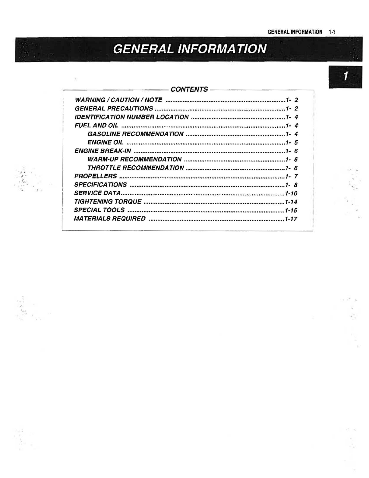
GENERAL INFORMATION
WARNING/CAUTION/NOTE
....................................... .............................. 1- 2
GENERAL PRECAUTIONS ............
..
.............
..
..............................
..
............
..
1-
2
IDENTIFICATION NUMBER LOCATION ......................................
..
............
..
1- 4
FUEL
AND
OIL .........
....
..
.......
..
.............
..
....
..
...................
..
............
..
.............. 1- 4
GASOLINE RECOMMENDATION ..........................................
..
............. 1- 4
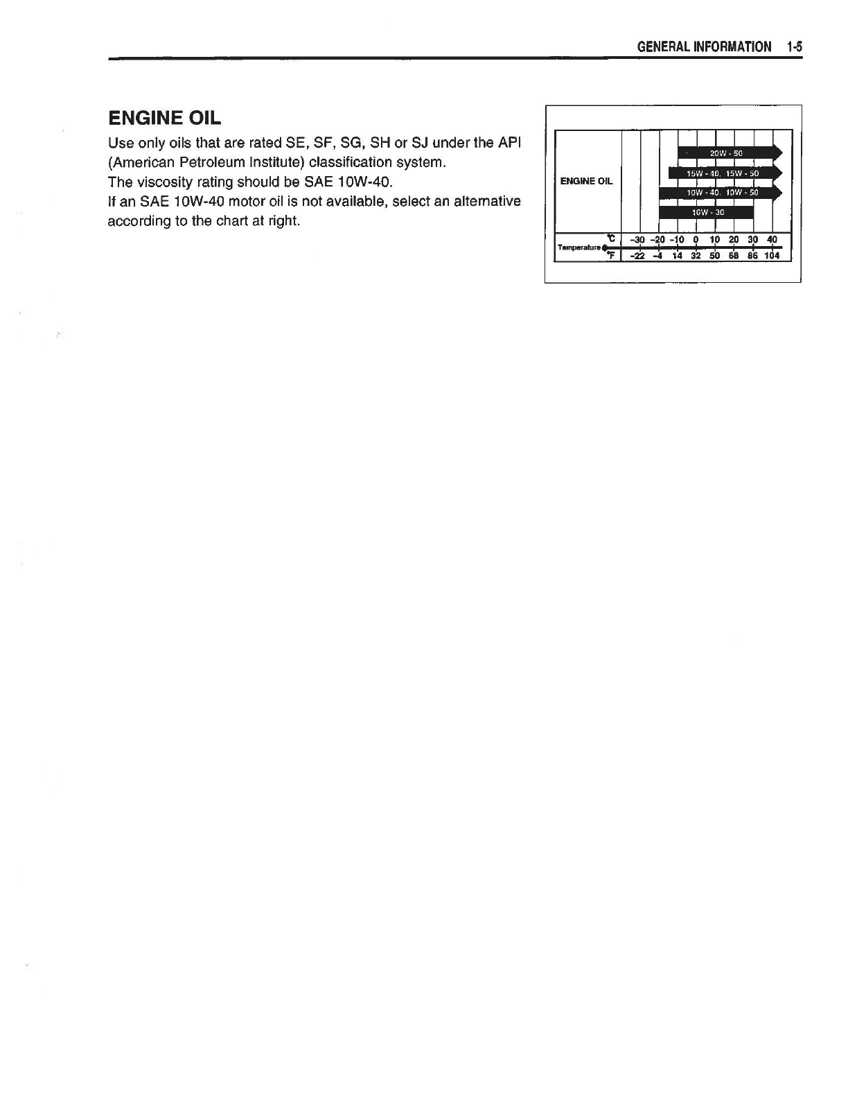
ENGINE OIL .............................................................
..
................ ............1· 5
ENGINE BREAK-IN .........................
..
............
..
................................
..
............ 1- 6
WARM-
UP
RECOMMENDATION ..........................................................
1-
6
THROTTLE RECOMMENDATION .........................................................1- 6
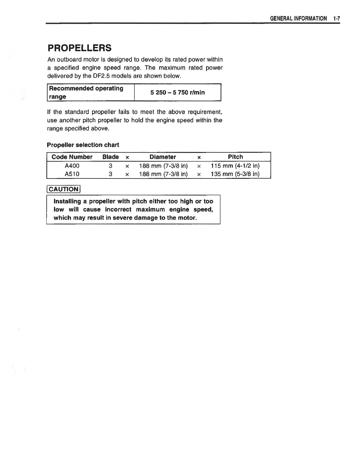
PROPELLERS
..
...........................
..
.................................................
..
............. 1- 7
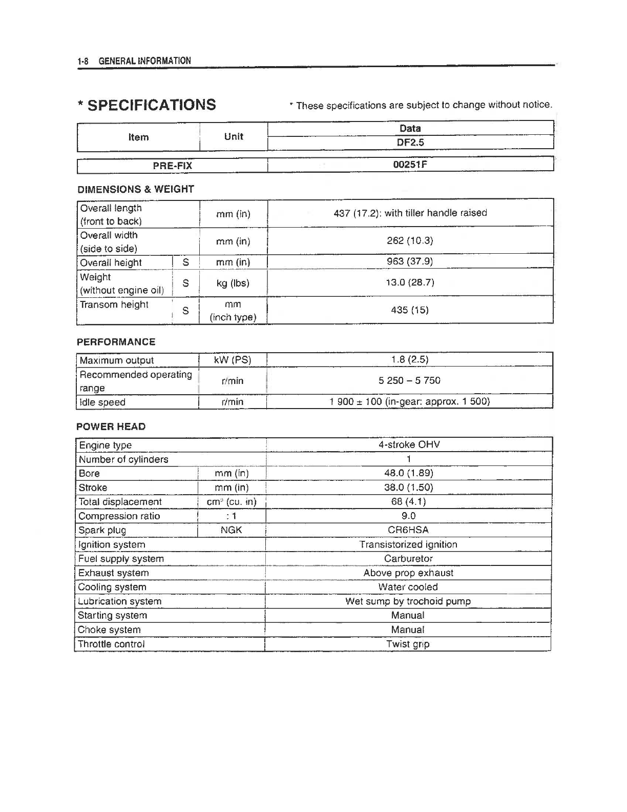
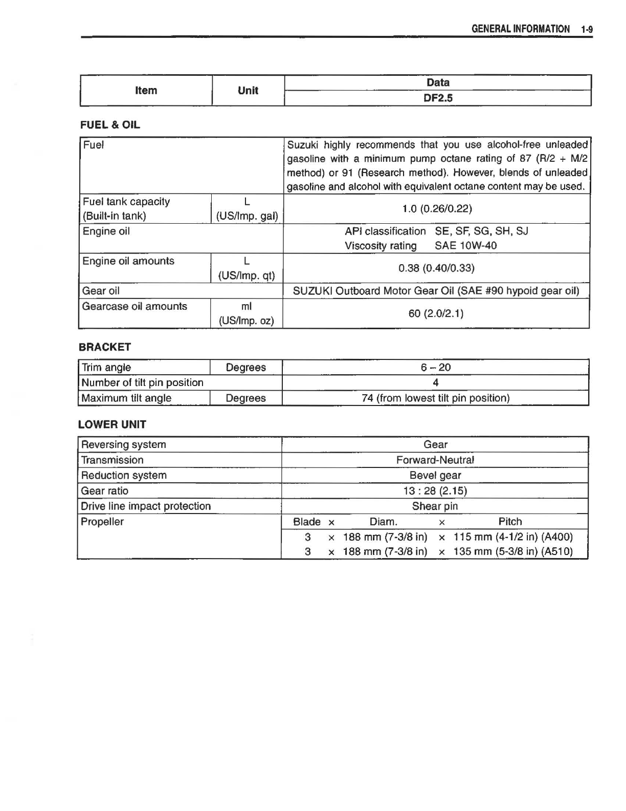
SPEC/FICA TIONS ........
..
................
..
..
..
......................................................... 1- 8
SERVICE DATA.............................................................................................. 1-10
TIGHTENING TORQUE
..
....................................................................
..
......... 1-14
SPECIAL TOOLS .............
..
...........................
...
...............................
..
....
..
..
..
..1-15
MATERIALS REQUIRED ...............
..
............................................
..
...............
1-17