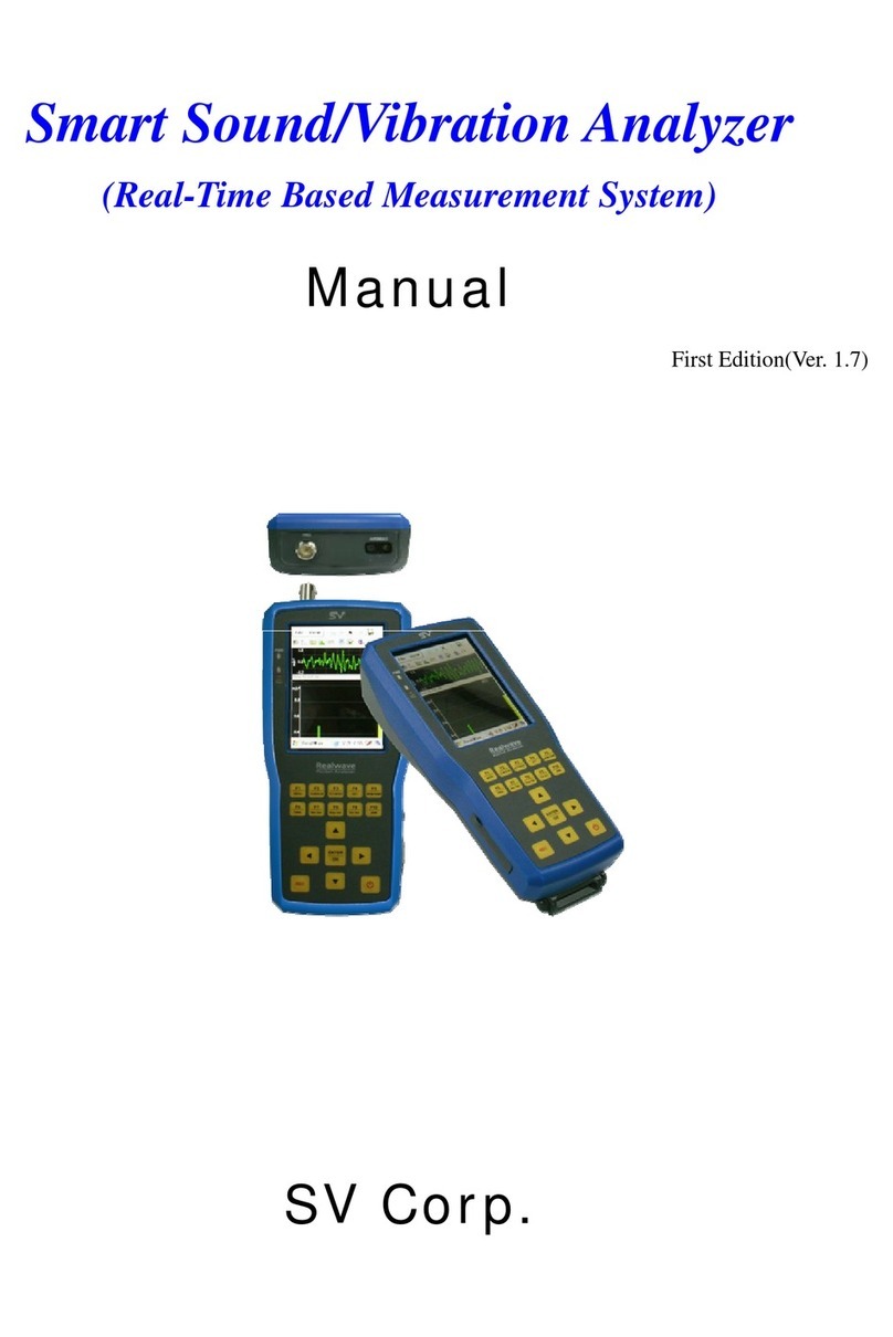
SV S12 User manual

1
Sound Level Meter & Nosie dosimeter S12
User Guide 1.2
Document Version : 1.2
Date : 17th February, 2021
SV CORPORATION

2
Table of Contents
1. Sound Level Meter ................................................................................................................................................................4
2. Connection ................................................................................................................................................................................4
3. Noise measurement..............................................................................................................................................................5
3.1. Power ON......................................................................................................................................................................5
3.2. Start measurement ...................................................................................................................................................5
3.3. Recording measurement........................................................................................................................................5
3.4. Toggle noise value display....................................................................................................................................6
4. Noise dosimeter......................................................................................................................................................................6
4.1 Noise DOSE (%) ..........................................................................................................................................................6
4.2 TWA (Time Weighted Average) dB(A) ..............................................................................................................7
4.3 Impulse noise...............................................................................................................................................................7
4.4 Projected Dose ............................................................................................................................................................8
4.5 Percentile noise level (ln)........................................................................................................................................8
5. Menus..........................................................................................................................................................................................9
5.1 Enter the main menu................................................................................................................................................9
5.2 Mode................................................................................................................................................................................9
5.3. Common..................................................................................................................................................................... 10
5.4 Analysis Options ...................................................................................................................................................... 15
5.5 Recording Options.................................................................................................................................................. 15
5.6 GPS................................................................................................................................................................................. 17
5.7 Print ............................................................................................................................................................................... 17
6. Specifications......................................................................................................................................................................... 17

3
7. Example; Printout form..................................................................................................................................................... 19
8. Distribution history............................................................................................................................................................. 20
■Appendix A. Keypad button.......................................................................................................................................... 21
■Summary main screen ..................................................................................................................................................... 22
■Measurement(START)........................................................................................................................................................ 22

4
Sound Level Meter & Nosie dosimeter S12
1. Sound Level Meter
Sound level meter S12 measures and displays the analog noise waveforms numerically. Sound
Pressure Level, Equivalent Continuous Sound Level or Leq, Peak, etc. are displayed in decibels.
Sound pressure 20 (μPa, microwave Pascal) is set as a reference level. It consists of a frontend and
a sensor. It is portable and easy to use.
2. Connection
Figure 1) is a conceptual diagram of system connection. In the figure, a microphone is attached
to the calibrator.
Figure 1) Connection
Sound Level
Meter
Sound calibrator
Microphone

5
3. Noise measurement
3.1. Power ON
Press the <POWER> button to turn on the device. The device is in a suspended state.
3.2. Start measurement
Press the <ENTER> key. The device will display 'Stn' at the top right of the screen and start the
measurement. ‘Stn’ means ‘Standby’ mode. The system waits 10 seconds for the signal to stabilize
and then switches the display to Arm. Press <ENTER> again to stop the measurement. In this
mode, data is not saved to the SD card. This mode is called the “A rming mode”.
3.3. Recording measurement
In “Arming mode”, press the <REC> button on the keypad. The device will immediately display
'Rec' at the top right of the screen and start recording. This mode is called “Recording mode”. In
this mode, data is stored on the SD card. Press the <REC> button again to stop the measurement.
When the time elapses, it stops saving and switches to “Arming mode”. To pause the recording
temporarily, please press F4. You can see the symbol “===” during this pause. If you want to end
the pause and continue recording press again the F4 button. It will continue recording and the
symbol === will disappear from screen. But during this pause period, processing of noise/sound
is continuously going on, but not recording. So the pause (F4) is only for recording. There is no
pause for arming mode. Timer setting is explained in 5.5 RECORDING OPTIONS.
The file name ‘YYMMDD_HHMMSS.txt’ is displayed in the lower right corner during saving. This
result text file is saved in folders with the mode name. For example, if measurement mode is SLM,
the result file will be stored in SLM/ folder. Similarly if the mode is ND, the result files are stored
in ND/ folder. Please note that for all modes the file name is same format as explained in the
beginning this paragraph. If the user presses the <REC> button in idle mode, it displays 'Stn' and
waits 10 seconds without recording. After that, display 'Rec' and start recording measurement.

6
3.4. Toggle noise value display
When you press the F2 key, the device displays sound pressure level(SPL). 'LAF' is displayed on
the upper left of the screen. Each press of the F2 key toggles the quantification of noise in the
order LAF, LAFmax, LAFmin, and LApeakMax. The user can press F1 to view the equivalent
continuous sound pressure level (Leq). In this case, LAeq [In], LAeq [Avg], LAmax, LAmin,
LpeakMax, L10, L30, L50 and L90 are switched in this order. You can change the frequency
weighting (Z, A, B, C) and time constant (F, S, I) in 5.4 ANALYSIS OPTIONS.
4. Noise dosimeter
A noise dosimeter (American English) or noise dosemeter (British English) is a
specialized sound level meter intended specifically to measure the noise exposure of a person
integrated over a period of time; usually to comply with Health and Safety regulations such as
the Occupational Safety and Health (OSHA) 29 CFR 1910.95 Occupational Noise Exposure
Standard or EU Directive 2003/10/EC.
4.1 Noise DOSE (%)
The amount of actual exposure relative to the amount of allowable exposure, and for which
100% and above represents exposures that are hazardous. The noise dose is calculated according
to the following formula:
1) Variable noise field
D = [C1/T1 + C2/T2 + Cn/Tn] × 100
2) Constant noise field
D = [C/T] ×100
Where:
Cn = total time of exposure at a specified noise level
Tn = exposure time at which noise for this level becomes hazardous
C= Actual Exposure Time
T= Permissible Exposure Time

7
4.2 TWA (Time Weighted Average) dB(A)
The TWA shows a worker's daily exposure to occupational noise (normalized to an 8 hour
day), taking into account the average levels of noise and the time spent in each area. This is the
parameter that is used by the OSHA Regulations and is essential in assessing a workers
exposure and what action should be taken.
1)8hours Time Weighted Average level (dBA)
The averaging of different exposure levels during an exposure period. For noise, given an
90dBA (exposure limit and a 5dB (exchange rate, the TWA is calculated according
to the following formula: (= ISO Standard
- OSHA; TWA=16.61log(D/100)+90
- ISO; TWA=10log(D/100)+85
D=Dose(%)
T=Measurement time (OSHA;T=
, ISO; T=
)
2) Time Weighted Average level ((dBA)), (measuring time< 8hr, measuring time>8hr)
- OSHA; TWA=16.61log(D/12.5×T)+90
- ISO; TWA=10log(D/12.5×T)+85
D=Dose(%)
T=Measurement time
4.3 Impulse noise
Impulsive noise is characterized by a sharp rise and rapid decay in sound levels and is less than
1 sec in duration. For the purposes of this document, it refers to impact or impulse noise.

8
4.4 Projected Dose
Dose measurements usually require the noise exposure to be measured over a full 8 hour
working day. This can be simplified by using projected dose.
This dose allows the present accumulated dose over the logged time duration to be projected
forward to give the predicted 8 hour dose. This can be shown by the equation as below.
Projected Dose=
4.5 Percentile noise level (ln)
Ln, where n may be anything from 1 to 99, is that noise level exceeded for n% of the
measurement time. By definition of percentiles, L1 must be greater than or equal to L2, which
must be greater than or equal to L3, etc. It is often the case that only a few Ln values are ever
used.
An example of how Ln values look in a graphical format:
Percentile levels
L90 is frequently taken as the Lp of the background level. L10-L90 is often used to give a
quantitative measure as to the spread or “how choppy” the sound was.
L10 is the noise level exceeded for 10% of the time of the measurement duration. This is often
used to give an indication of the upper limit of fluctuating noise, such as that from road traffic.

9
L50 is the noise level exceeded for 50% of the measurement duration. It is the middle point and
has been incorporated in some American Community Noise Assessments.
L90 is taken to be the ambient or background noise level.
L10-L50 is often used in such noise indices as Traffic Noise Index:
TNI= 4 · ( - + +30 (dB)
5. Menus
5.1 Enter the main menu
The user presses the F5 (Menu/Back) key to enter the main menu. The device then stops
measuring and displays the next menu.
Item
Description
5.2
Mode
To select SLM or Noise Dosimeter
5.3
Common
1) Setting
To set the measurement condition
2) Time date
To edit the time and date
3) Device Options
To set the device condition
4) Information
To show the system information
5) Serial Number
To enter the device serial number
5) Calibration
To calibrate the sensor
5.4
Analysis
Options
1) Sound level meter
To analysis measurement data
2) Noise dosimeter
3) Percentile level
5.5
Recoding
Options
1) Sound level meter
To set the recording conditions
2) Noise dosimeter
3) Percentile level
5.6
GPS
To show the GPS data
5.7
Print
To select the data and print out
5.2 Mode
1) Sound level meter
2) Noise dosimeter

10
5.3. Common
1) Settings
①Refres Tim, ‘Refresh Time’To select the refresh rate.
{0.3,0.5,1,5 seconds},
default : 1 seconds
②PwrOnStart, ‘Power On Starting’Measurement starts automatically when power is applied.
{Off,On},
default : off
2) Time and date
Set the time and date. The <◀/▶ LEFT/RIGHT> key moves the cursor. The <▲/▼,
UP/DOWN> keys scroll through the values. Move the cursor to 'OK' and press the <ENTER> key
to complete the setting. Selecting the Cancel key cancels it.
3) Device Options
Select the device option. There is an LCD backlight on time or an auto power off time.
①Backlight, Select the backlight on time.
<Not use> : Turn off the backlight of the LCD. ←
default
<5 sec> : LCD backlight turns off 5 seconds after keypad button is pressed.
<10 sec> : LCD backlight turns off 10 seconds after keypad button is pressed.
②Auto pwoff, ‘Auto power off’If there is no key input after stopping the measurement, the
device will be turned off.
<5 min> : The device turns off after 5 minutes.
<10 min> : The device turns off after 10 minutes.
<Not use>; Not adopt “auto pwoff” ←
default
③s/w update, ‘Software update’Update the firmware.
Selecting this item will display a warning message. If you are not informed by the SV

11
Corporation, you must press F5 to cancel. When prompted, press the OK button to
proceed with the update.
4) Information
Display system version information.
Sound Level Meter/Noise Dosimeter
SV Corporation
Ver.;
Algorithm;
Serial Number;
5) Serial Number
User needs to enter his SLM device number. Device serial number is a 12 digit alpha-numeric
number, written on the backside of the device. Enter the last 5 digits of the serial number in this
filed. This serial number will be shown in summary print receipts, all result text files of all modes.
6) Calibration
It consists of the following submenus.
Start
Start calibration.
Transducer
Set up the transducer and calibrator.
Back
Return to the main menu.
(1) Calibration process
①Plug the microphone into the calibrator.
②Press the <POWER> button to turn on the power.
③Press <▲, UP> key on the main menu to select 'CALIBRATION'. This will enter the
calibration assistant menu.
④Scroll to the <▼, DOWN> key and select the ‘Transducer’ item. Then select the desired
values.
Sensitivity : 50.0mV/Pa
Nomi RMS, Nominal RMS : 94.0 dB, 114 dB,
Nomi Freq, Nominal Frequency : 1000.0 Hz

12
Calibr Coef , Calibration Coefficient : 1.0
⑤Press the <▲/▼, UP/DOWN> buttons to move the cursor to OK/Cancel. Then press the
<ENTER> key.
⑥Turn on the calibrator.
⑦Press the <ENTER> key to select the "Start" item. “Preparing…” and “Processing…” Is
displayed.
After 1 minute has elapsed, the correction coefficient is finally displayed as 1.0xxxx.
If the OK button is pressed while the calibration is in progress, the calibration stops.
⑧Press <ENTER>, scroll down and press ‘Back’. The calibration coefficients are
automatically stored in nonvolatile memory, so they remain on even if the power is
turned off.
6) Print; Print options
(1) Show files; All, last 50, last 30 selectable with <▲/▼, UP/DOWN>button
■Print out format (Report)

13
①SLM Measurement Report

14
②Noise Dosimeter Measurement Report
Self-explanatory reports of ND mode are shown below.
(3) Percentile noise (Ln) report format
Ln repots is similar to the print report shown as in SLM and ND modes. In this mode results are L1, L5,
L10, L30, L50, L90, L95 and L99.

15
5.4 Analysis Options
1)Sound level meter
①Integral, Select a data analysis type.
<SPL>, Sound pressure level
<Leq>, Sound equivalent continuous pressure level
<Ln>, Percentile noise level
②IntegratTime, ‘Integration Time’Select the integral period of Leq, Ln
{0.1, 0.2, 0.5, 1,2,5, 10 seconds and recording time in Leq and Ln}
default: 0.1 sec
③Freq Weight, ‘Frequency Weighting’Select a frequency weighting.
{Z,A,B,C}, Weighting
default: A
④Time Const, ‘Time Constant’To select the time constant.
{F,S,I}, Fast, Slow, Impulse,
default : F
2)Noise dosimeter
(1)Standard ; OSHA, ISO, selectable with <▲/▼, UP/DOWN>button
(2) Output : TWA dB(A), Dose(%), SPL(Inst), prjDose, selectable with <▲/▼, UP/DOWN>button
(3) Setup conditions, All parameters are changed by OSHA, ISO setting conditions
①Exchange rate; 5dB(OSHA), 3dB(ISO)
②Time weighting; Slow(OSHA), Fast(ISO)
③Frequency weighting; A(common)
④Criteria; 90dB(OSHA), 85dB(ISO)
⑤Threshold; 80dB(OSHA), 75dB(ISO)
⑥Display output type; Noise dose(%), TWA dB(A)
3) Percentile level
L1, L5, L10, L30, L50, L90, L95, L99%; selectable with <▲/▼, UP/DOWN>button
5.5 Recording Options
Select the recording time option. This timer is used in 3.3 recording measurement.
1)Sound level meter
①Rec Timer, ‘Recording Timer’To select the recording time.

16
{1 sec,2 sec,3 sec,5 sec,10 sec,1 min,5 min, 10 min, 20min, 25min, 30min, 1h, 4h, 6h, 8h,
12h, 16h and 24h }, Record for 1 second ~ 24 hours
2)Noise dosimeter etc.
Select data noise patterns and recording time
(1)Type ; Steady noise[SN], Non steady noise[nSN], Impulse noise[IN],
Selectable with <▲/▼, UP/DOWN>button
(2) Rec Per Hour ; 3, 10, 30,60 times, Selectable with <▲/▼, UP/DOWN>button
(3) Duration[nSN] ; 1, 2, 3, 4, 6, 8, 10, 12, 24 Hours, Selectable with <▲/▼, UP/DOWN>button
(4) TrigLevel[IN] ; 60, 70, 80, 90, 100, 110, 120 dB, Selectable with <▲/▼, UP/DOWN>button
(5) Timer[IN] ; 1,3, 5,10, 20, 30, 45, 60 second, Selectable with <▲/▼, UP/DOWN>button
3) Recording
(1) Steady and non-steady noise; noise Dosimeter mode
Files are saved to ND folder to SD card. Format file name: yymmdd_hhmmss.txt Result are
saved to file with frequency of “Rec Per Hour” parameter in case if SPL > Threshold (fixed
parameter). Duration of measurement is 1 hour for Steady mode(fixed) and “Duration[nSN]”
hour for non-Steady mode.
(2) Impulse noise; noise Dosimeter mode
After click <REC> button system waits when LPeak >TrigLevel[IN] option, after that system
starts real recording with frequency 1 time/sec and duration Timer[IN] sec. Files are saved
to ND folder of SD. Format of file’ name: yymmdd_hhmmss.txt.
(3) Percentile noise; SLM Mode
LN. Files are saved to LN folder of SD. Format of file’ name: yymmdd_hhmmss.txt. Timer is
selectable from SLM recording mode, Record for 1 second ~ 24 hours, result are saved to
file with frequency IntegratTime (Menu/Analyzing Options/SLM)
(4) SPL & Leq; SLM Mode
Files are saved to SLM folder of SD. Format of file’ name: yymmdd_hhmmss.txt
->Start Record data; press “REC” button; 00:00/04h:00(Displayed pattern)
(depends on Recording options 5.5-2) setting)
->Stop Record data; Repress “REC” button, Finish Recording according to setting condition
Ex) Rec Per Hour ; 10 times, Duration ; 4hr -> 00:10/04h:00 ( file check; Print->5.7-2)
->Pause recording: During recording press F4, then the recording will be paused. And a
symbol “===” will be shown on the top of the screen. During pause the measurement is still

17
going on in Arming mode but not recording to file. To come out of the pause mode, press again
F4, then the recording will resume.
5.6 GPS
Display “location coordinates”on the LCD and will be printed out when user press the “Report
format”. During measurements, if GPS signal is available you can see a symbol “G” on screen. If
GPS signal not available it will show as “N”. GPS signal most probably available on outside
locations only. On print reports GPS coordinates are visible only if the GPS signal is available at
the beginning of recording.
1) GPS ; On, Off , Selectable with <▲/▼, UP/DOWN>button
5.7 Print
1) Basic print set up; Common 6)
2) Printing; Select Files , press print button->file will be shown, select-> press ENTER(starting
print), before printing start, need to connect between S12 and printer with RS232 cable.
■ Printing guide
(1) File printing function is provided for Noise Dosimeter and SLM (only LN) modes.
(2) To print files of Noise Dosimeter measurements; Device should be in Noise Dosimeter
mode. ->Select Menu/Print files of ND folder are displayed.
->Select file and click <Enter> button.
(3) To print files of LN measurements in SLM mode; Device should be in SLM mode, level LN.
->Select Menu/Print files of LN folder are displayed.
->Select file and click <Enter> button
(4) To print files of SLM measurements in SLM mode; Device should be in SLM mode, level
Leq/SPL.
->Select Menu/Print files of SLM folder are displayed.
->Select file and click <Enter> button
6. Specifications
Sound level meter kit includes: main instrument, microphone SV-MC3 and cable, instruction
manual, plastic case

18
Size : 190 mm x 90 mm x 30 mm (without Microphone)
Weight : 290 g (Frontend, without Microphone)
OS : RTOS
CPU : ARM Cortex-M7 (300MHz)
Memory : 32GB
Environmental
Operating temperature range: 0 °C to 50°C
Storage temperature range: -20 °C to 70°C
Humidity : 5% ~ 95% Non-condensing
Power supply : DC 3.7V 0.4W
Battery life : typically 32 hours, auto power off
Time required for full charge : 6 hour
A/D converter : 24 bit
Displayed Sound Units
Leq in dB
SPL in dB
Input Channel : 1 channel sound
Sensor Type : IEPE
Sample Frequency : 22.05 kHz
Measuring range : 30~140dB - auto
Signal to noise ratio : higher than 68 dB
Type : Class 1 accuracy

19
7. Example; Result files
SLM result file -
ND result file –
Ln mode result file -

20
8. Distribution history
Date
Change history
2020.11.11
Release 1st state program for noise dosimeter
2021.02.17
SLM & Ln mode 24 hours recording, recording pause, Print report in
SLM mode, Print report corrections
Table of contents
Other SV Measuring Instrument manuals