Sven OVP-17P User manual

USER’S MANUAL
www.sven.fi
OVP-17P
Voltage Relay

ENG
Voltage Relay
3
3
4
4
4
6
6
8
9
Congratulations on your purchase of the SVEN voltage relay!
COPYRIGHT
© 2017. SVEN PTE. LTD. Version 1.0 (V 1.0).
This Manual and information contained in it are copyrighted. All rights
reserved.
TRADEMARKS
All trademarks are the property of their legal holders.
NOTICE OF RESPONSIBILITY RESTRICTION
Despite the exerted efforts to make this Manual more exact, some discre-
pancies may occur. The information in this Manual is given on “as is” terms.
The author and the publisher do not bear any liability to a person or an or-
ganization for loss or damage which has arisen from the information con-
tained in this Manual.
CONTENTS
1. PRECAUTIONS .........................................................
2. PACKAGE CONTENTS ..................................................
3. APPLICATION ...........................................................
4. FEATURES ...............................................................
5. TECHNICAL DESCRIPTION ...........................................
6. CONNECTION ............................................................
7. PREPARATION TO OPERATION ......................................
8. OPERATION ..............................................................
9.
TECHNICAL SPECIFICATIONS
.......................................
Technical support is on www.sven.fi.
2

OVP-17P
ENG
User’s Manual
The device must operate in the power network protected by an
automatic circuit breaker with the interrupting current not more
than 15 А.
The device is not designed for power-cut while short-circuited.
Attention
1. PRECAUTIONS
• Before using the device, please carefully read the following User’s
Manual and save it for the whole operation period.
• Before connecting the device to the power supply network, keep it within
two hours in operating conditions.
• Do not use abrasive materials or organic compounds (alcohol, petrol,
solvents etc.) to clean the device.
• It is prohibited to open and repair the device on your own.
• It is prohibited to open and repair any protected equipment, if it is con-
nected to the device socket.
• It is prohibited to use the device with mechanical damages of its case.
• It is prohibited to use the device in high humidity conditions.
• Avoid ingress of water into the device.
• Shipping and transportation equipment is permitted only in the original
container.
• Does not require special conditions for realization.
• Dispose of in accordance with regulations for the disposal of household and
computer equipment.
2. PACKAGE CONTENTS
• Voltage relay – 1 pc
• User’s Manual – 1 pc
• Warranty card – 1 pc
3

ENG
Voltage Relay
3. APPLICATION
OVP-17P voltage relay is designed to protect household appliances (refri-
gerators, washing-machines, PCs, video and audio equipment, etc.) con-
nected to it against inadmissible supply voltage deflections and impulse
noises in the power supply network.
4. FEATURES
• Protection of connected devices against high/low voltage in the power
supply network
• Protection of connected devices against impulse noises in the power
supply network
• Programmable disconnection thresholds and turn-on delay time
• Nonvolatile memory of programmed settings
• Multifunctional LED display to show voltage level in the power supply net-
work, delay time and protection status indication
• Protective shutters in the output socket
• Protective grounding connection
5. TECHNICAL DESCRIPTION
OVP-17P voltage relay presents a device with an electronic circuit with
microprocessor control assembled in a case with a wall plug and socket.
OVP-17P voltage relay provides the power supply disconnection of appliances
connected to it, if the power supply voltage exceeds specified values, and
automatically recovers the power supply within the specified time after
voltage normalization. An indicator on the front panel displays the active
voltage value in the power supply network and signals about its operation
mode. OVP-17P voltage relay is a programmable device. Buttons on the
front panel are used to set its parameters.
Set parameters of the voltage relay are saved in its nonvolatile memory.
4

OVP-17P
ENG
User’s Manual
h
e
f
g
b
c
d
a
SET
Реле напряжения
15 А
OVP-17P
RES
V
V
Design description (Fig. 1)
a Four-digit LED indicator to display voltage value of the power supply
network, values of parameters being set and the voltage relay status
indication
b SET: button to enter the programming mode and select programmable
parameters
c Λ: button to increase the value of a parameter being set
d V: button to decrease the value of a parameter being set
e RES: reset button
f Protective shutters
g Grounding contacts
h Wall plug to connect the voltage relay to ~220 – 230 V / 50 Hz power
supply network socket
Fig. 1
5

ENG
Voltage Relay
6. CONNECTION
OVP-17P voltage relay is connected to a standard socket of ~220 – 230 V /
50 Hz power supply network. The socket must be rated at the current 15 A.
The power supply line of the socket must be protected by an automatic
circuit breaker with current not more than 15 A to protect against short
circuit and overload. Protected devices are connected to the output socket
of the voltage relay. The long consumption current of devices being
connected to the relay must not exceed 2/3 of the maximum load current
indicated in their specification.
The voltage relay is designed for operation indoor only. The device ope-
ration is inadmissible in places with high humidity and where ingress of
liquid on its case is possible. Ambient temperature during the voltage relay
operation must be in the range +10 to +35 °С.
Before connecting equipment to the voltage relay it is necessary to set
actuation values, namely, high voltage switching off threshold (UH), low
voltage switching off threshold (UL) and turn-on delay time after voltage
normalization of the power supply network (td) (see p. 7). It is recom-
mended to set these values in accordance with operation manuals of
connected equipment. As a rule, household appliances can operate safely
at 10 % supply voltage deviation, i.e. in the range 198-242 V. The turn-on
delay time value after allowable voltage renewal is selected depending on
the type of connected electrical appliances. For refrigerators, air-con-
ditioners and other compressor devices the delay value should be not less
than 3 minutes.
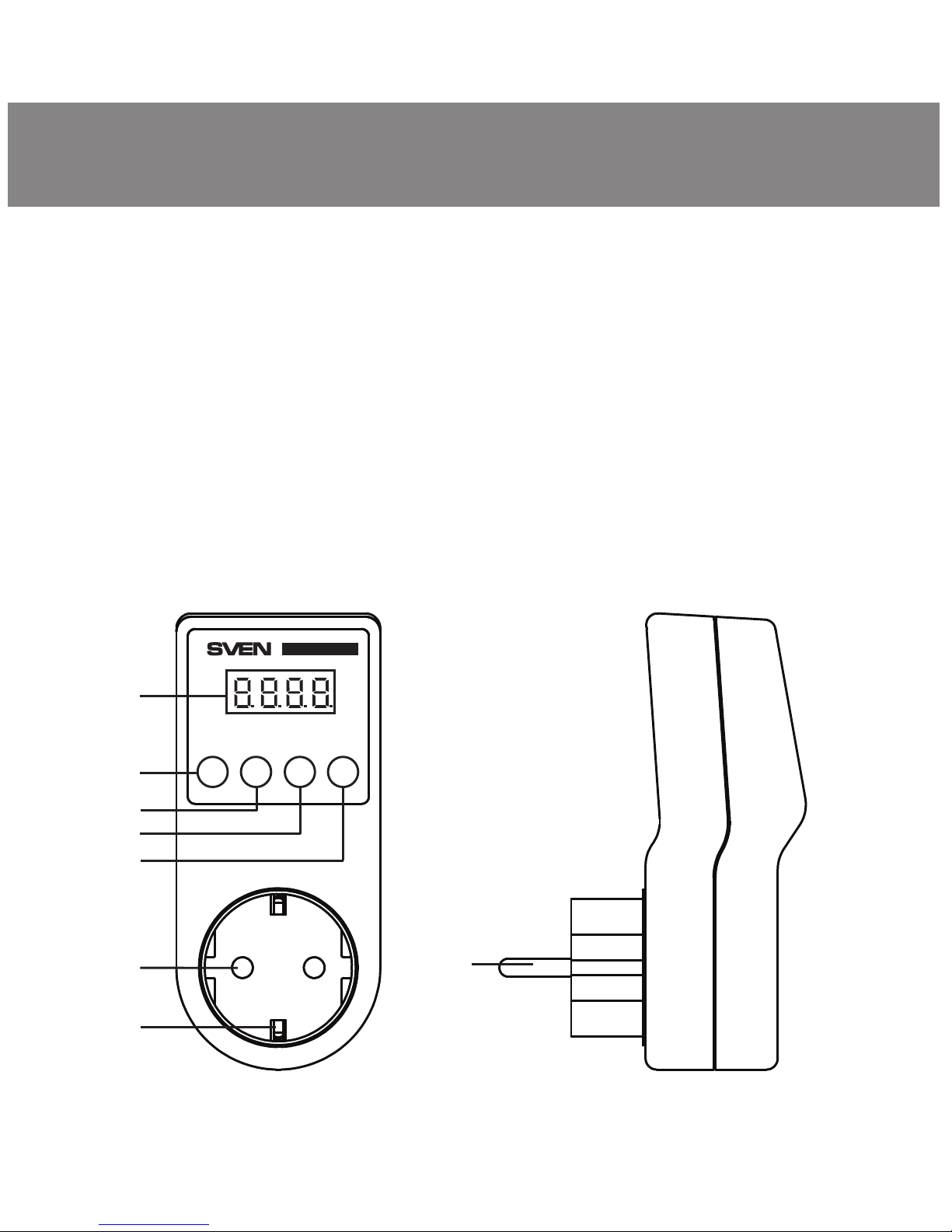
7. PARAMETER SETTINGS
• Connect the voltage relay to a ~220 – 230 V / 50 Hz socket to set
protection parameters. The display shows its model name for a short time
and the zero time reference will start to switch on the relay output.
• Enter the parameter setup mode holding the button “SET” within 3 se-
conds. There will be flashing “H” symbol and the upper switching-off
threshold value (UH) in volts on the display a. Set a required value using
6

OVP-17P
ENG
User’s Manual
buttons “Λ” c and “V” d. The range of possible values of the UH para-
meter is 230 to 265 V / 50 Hz.
• Start setting lower switching-off threshold value by pressing the button
“SET” b. There will be flashing “L” symbol and the upper switching-off
threshold value (UL) in volts on the display a. Set a required value using
buttons “Λ” c and “V” d. The range of possible values of the UL para-
meter is 150 to 210 V.
• Start setting turn-on delay value by pressing the button “SET” b. There
will be the flashing “d” symbol and delay value (td) in seconds on the
display. Set a required value using buttons “Λ” c and “V” d. The range of
possible values of the td parameter is 5 to 999 seconds.
• The set parameters will be saved in the voltage relay nonvolatile memory
in 5 seconds after the last button press. At that the “SAVE” inscription will
be displayed for a short time, the voltage relay enters the operation mode
with new settings and the zero time reference will start to switch on the relay
output.
• When the protection actuation parameters of the voltage relay have been
set, connect protected equipment to its socket.
• When the delay time is over, the relay will provide power supply to the
protected equipment. At that, the indicator a will display the active voltage
in the power supply network.
• Where it is necessary to reset parameters of the voltage relay to factory
settings, push the button “RES” e. Then there will be the "deF_H245_
L175_d180" creeping line on the display a and the voltage relay enters the
operation mode with the following parameter values: UH = 245 V, UL = 175 V,
td = 180 sec.
7

8. OPERATION
The voltage relay has the following operation modes:
- normal operation;
- protection mode;
- turn-on delay mode;
- parameter settings mode.
The voltage relay is in the normal operation mode, when the active power
supply voltage is within the range of voltage actuacion protection
thresholds having been set by a user and the turn-on delay time is over. In
this mode the protected equipment is connected to the power supply
network and active voltage in the network is displayed continuously.
If the voltage exceeds the set thresholds, the relay enters the protection
mode. In this mode the equipment connected to the relay is de-energized.
The “Hi” symbol and voltage value in the power supply network will blink by
turns on the display (on operation of high voltage protection) or the “Lo”
symbol and voltage value in the power supply network (on operation of low
voltage protection). The voltage relay will be in this mode as long as the
voltage in the power supply network returns to the range of values from
(UL+5) V to (UH-5) V.
The relay enters the turn-on delay mode after its connection to the network
or when it leaves the protection mode. In this mode the equipment con-
nected to the relay is de-energized and the countdown time of turn-on
delay is displayed. When the time is over the relay enters the normal ope-
ration mode.
The parameter settings mode is used to adjust protection actuacion para-
meters. To enter this mode press and hold the button “SET” b within
3 sec, the mode is over automatically in 5 seconds after the last pressing of
any button.
ENG
8
Voltage Relay

Parameters
Rated voltage, V / Hz
Maximum load current, А
Maximum power, kVА
Maximum absorbed impulse noise
power, J
Protection actuation time
Measured voltage, V
Range of possible adjustable
parameter values:
- operation threshold to decrease
power supply voltage, V
- operation threshold to increase
power supply voltage, V
- delay time, sec
Dimensions, mm
Value
~220 – 230 / 50
≤15
≤3.3
125
not more than 0.3 sec
100 – 300
150 – 210 (1 V step)
230 – 265 (1 V step)
5 – 999 (1 sec step)
53 × 116 × 80
Notes:
• Technical specifications given in this table are supplemental informa-
tion and cannot give occasion to claims.
• Technical specifications and package contents are subject to change
without notice due to the improvement of SVEN production.
9.
TECHNICAL SPECIFICATIONS
9
OVP-17P
ENG
User’s Manual

Model:
OVP-17P
Импортер в России: ООО «РЕГАРД», 109052,
РФ, г. Москва, ул. Нижегородская, д. 86, корп. Б.
Уполномоченная организация в России:
ООО «РТ-Ф», 105082, г. Москва, ул. Фридриха
Энгельса, д. 75, стр. 5.
Условия гарантийного обслуживания смотрите
в гарантийном талоне или на сайте www.sven.fi.
Гарантийный срок: 12 мес. Срок службы: 2 года.
Производитель: «СВЕН ПТЕ. Лимитед»,
176 Джу Чиат Роуд, № 02-02, Сингапур, 427447.
Произведено под контролем «Свен Скандинавия
Лимитед», 48310, Финляндия, Котка,
Котолахдентие, 15. Сделано в Китае.
Manufacturer: SVEN PTE. LTD, 176 Joo Chiat Road,
№ 02-02, Singapore, 427447. Produced under the
control of Oy Sven Scandinavia Ltd. 15, Kotolah-
dentie, Kotka, Finland, 48310. Made in China.
® Registered Trademark of Oy SVEN
Scandinavia Ltd. Finland. OVP-17P
Voltage Relay
Table of contents
Other Sven Relay manuals