SVERO 1 SA User manual

SVERO Electric Winch -1 SA
200 – 1000 kg
User instructions
SVERO LIFTING AB, Alfavägen 4, 556 52 Jönköping, Sweden
Tel.: +46 (0)36-31 65 70, Fax: 036-31 65 79
www.svero.com, E-mail: info@svero.com

2
SVERO Electric Winch -1 SA
Read through these user instructions before using the winch. Improper operation may
lead to hazardous situations! These winches are intended solely for pulling. They are
delivered complete with wire rope and load hook and must be securely fixed to a stable
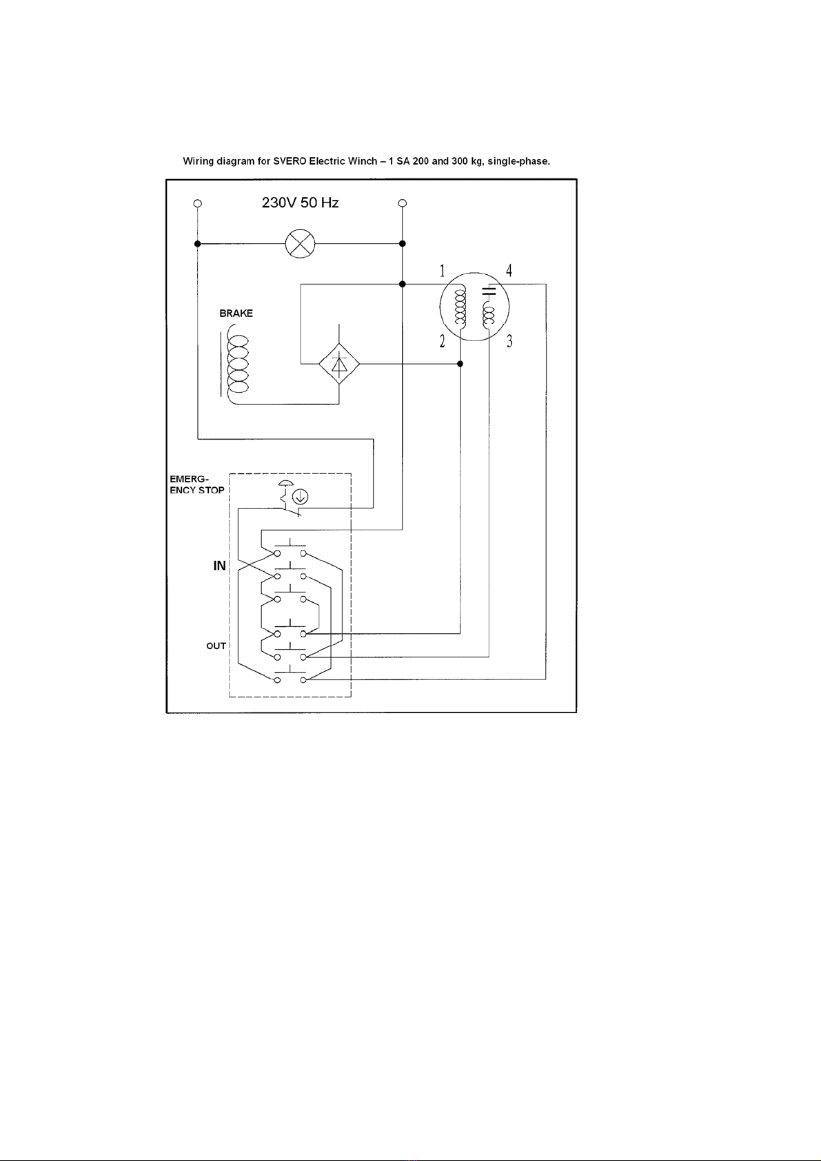
construction. Winches for 200 and 300 kg are single phase for plug connection to an
earthed single phase 230 V 50 Hz socket outlet. The winches for 500, 750 and 1000 kg
are only available in three-phase construction for 400 V 50 Hz and also have a plug, an
IEC 60309 connector, with an integral function allowing easy swapping of two phases.
Safety rules
•Check the winch and its function before use. The rope must be correctly wound
onto the drum. See Fig 3.
•Never exceed the maximum load.
•Attach the load with its load hook correctly to fixing eye, shackle or other working
point on the load. Never use the wire rope from the winch as a sling round a load.
•The winch must not be used for transporting persons.
•Make sure everyone keeps a safe distance from the load or wire rope.
•Protect the winch from rain etc.
•Ambient temperature -10°C – +40°C.
•Do not pull on the control or connection cable. Handle the winch with care.
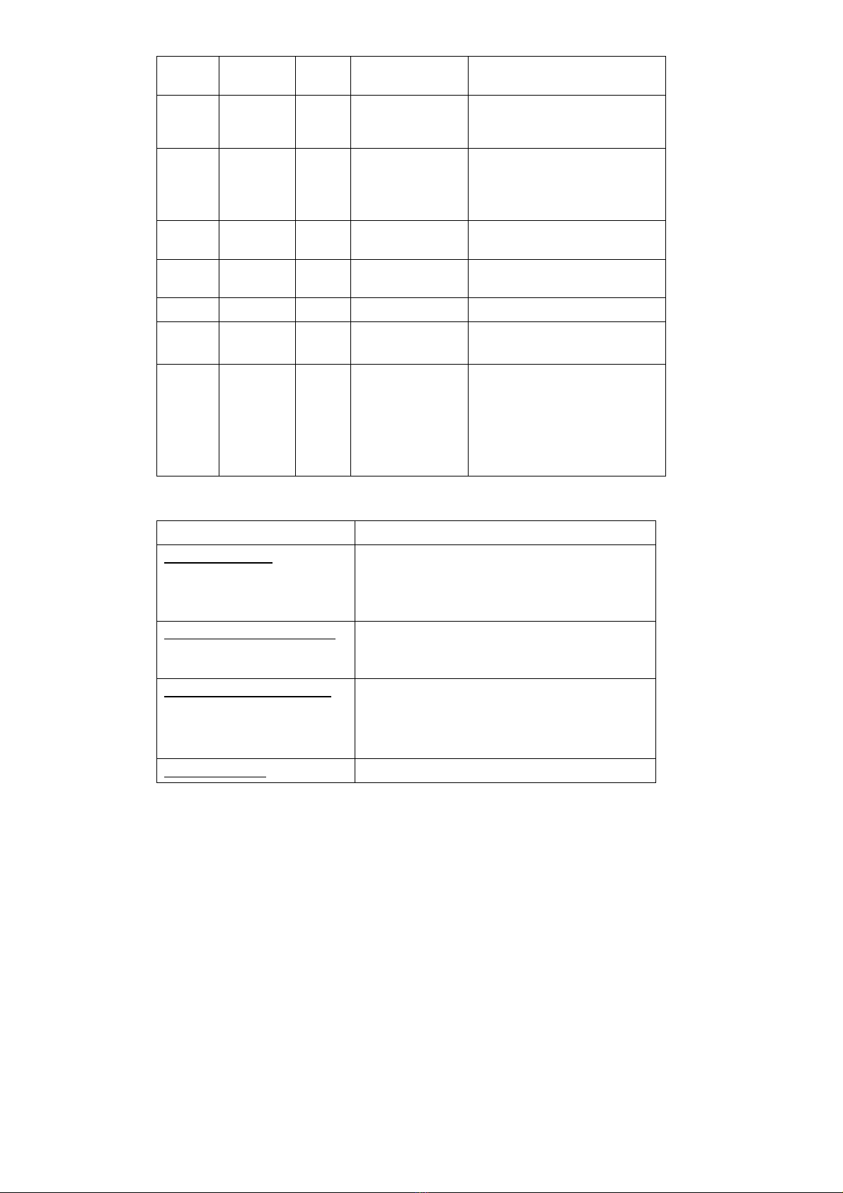
Technical data single-phase winch
Model 1 SA 200 1 SA 300
Maximum load (pulling capacity) daN (kg) 200 300
Rope diameter mm 6 7
Rope construction 7x19 7x19
Rope length, total m 30 30
Rope length, max. uncoiled length m 29 29
Rope speed m/min 10 – 15 10 – 15
Motor output kW 0.8 1.5
Voltage V single phase
230 single phase 230
Rated current A 9 10
Fuse, time-delay A 10 10
Protection form IP 65 IP 65
Weight incl. rope and load hook approx. kg 38 50

3
Dimensions table single-phase winch
Fig 1. Dimensioned sketch of single-phase winch
Technical data three-phase winch
Dimension
1 SA 200 1 SA 300
A mm 4 x dia.
10.5 4 x dia.
10.5
Bmm 142 172
Cmm 142 142
Dmm 515 540
Emm 210 210
Fmm 246 246
G mm dia. 94 90
Hmm 104 134

4
Dimensions table three-phase winch
Fig 2. Dimensioned sketch of three-phase winch
Model 1 SA 500 1 SA 750 1 SA 1000
Maximum load (pulling force) 500 750 1000
Rope diameter mm 9.3 9.3 11
Rope construction 6x19 +FC 6x19 +FC 6x24 +FC
Rope length, total m60 60 60
Rope length, max. uncoiled length 58 58 58
Rope speed m/min 12 –18 12 –18 12 –18
Motor output kW 3.0 4.0 5.5
Voltage Vthree-
phase 400 three-
phase 400 three-
phase 400
Rated current A4.8 6.5 8.7
Protection form IP 65 IP 65 IP 65
Weight incl. rope and load hook approx. 140 150 160
Dimension 1 SA 500 1 SA 750 1 SA 1000
Amm 4 x dia. 15 4 x dia. 15 4 x dia. 15
Bmm 400 400 400
Cmm 330 330 330
Dmm 922 950 950
Emm 372 372 372
Fmm 430 430 430
G mm dia. 140 140 140
H mm 240 240 240

5
Mounting the winch
Mount the winch on a stable construction with bolts of sufficient bearing capacity.
The wire rope
Winches are supplied with a wound-on wire rope fitted with load hook. Make sure the
wire rope is correctly wound onto the drum. See Figs. 3, 4 and 5. There must be at
least three rope turns on the rope drum when the rope is fully uncoiled. The rope exit
should be from the underside of the rope drum as shown on Fig. 6 to ensure minimum
strain on the winch fixings.
WARNING:
If the load hook is let out too far and the rope drum continues rotating, the rope will be
wound onto the drum again but in the wrong direction. This will damage the rope by
bending it in the opposite direction at the fixing. Risk of injury to persons and damage to
property.
Damaged rope must be replaced with new. See “Replacing the wire rope” on page 6.
Electrical connection
The single-phase model includes a connection cable (2.8 m) with earthed plug. This is
connected to a single-phase 230 V earthed socket outlet. Fuse 10 A, time-delay.
The three-phase model also has a connection cable (2.8 m) with an IEC 60309
connector for three-phase 400 V 50 Hz mains current. Check direction of rotation
immediately after connection. In the case of wrong direction, swap two phases. The
IEC 60309 connector has integral phase changeover for practical swapping of two
phases bearing in mind that the winch will often be used on different work sites.
NB If a three-phase winch is moved to a different work site, the direction of rotation
must always be checked before using the winch at the new work site.
Fig 3. Correct
(even) winding Fig 4.
Winding
too
widely
spaced.
Fig 5.
Winding
tangled
Fig 6. Rope exit
under the drum

6
Operation
Three-phase winches are operated with 24V control voltage. The control device with
2.8 m of rubber cable has one white and one black control button, with direction arrows
for IN and OUT respectively. Pressing the white control button must wind the rope onto
the drum (IN). In the case of wrong direction of rotation on the three-phase winch,
switch two phases, see above under Electrical connection.
There is also an EMERGENCY STOP device coloured red. If the emergency stop is
pressed, it can be reset by turning the red knob clockwise or by pulling the button out.
Attachment of loads
NB Improper attachment of loads can be highly dangerous (see Figs. 7, 8 and 9).
NB The winch is NOT fitted with limit switches. Always maintain an overview over the
load and the work area. Never leave a loaded winch unattended.
Checking with a test load
Check the winch before first use on a new work site. It is important to check the load-
bearing capacity of the fixing construction. Test it with a maximum load plus 10 %.
Make sure the load is not anchored to the ground or otherwise fixed.
All persons to keep a safe distance.
Daily checks
Before each working day on which the winch is used, the following must be checked:
• Is the winch or hook deformed or otherwise damaged?
• The rope must not be kinked, deformed or have broken wires.
• The brake function must be intact.
In the event of faults or failures, the winch must be carefully checked and if necessary
repaired by a specialist before reuse. If the rope is damaged it must be replaced.
Continuous inspection
Wipe down the winch as necessary. Check and oil the hook latch.
Fig 9 The wire rope
on the winch must
not be used as a
sling
Fig 7
Krokspärren
får ej
blockeras!
Fig 7 Do not load the
hook tip Fig 8 Hook latch
must not be
obstructed

7
Periodic checks
Periodic checks are normally carried out yearly to detect and remedy any faults. Check
the winch and its fixings and the condition and fixing of the rope and hooks. See also
Page 7.
Repairs
Winches must not be modified or the lifting purpose etc. altered. Repairs must be
carried out by specialists. Replace damaged parts with original SVERO parts. Order
them through your dealer.
Replacing wire rope
When replacing the wire rope, be sure to choose
the right rope (diameter and construction) as
indicated in "Technical data". Insert the end of the
new rope in the hole in the drum and pull it
towards the integral clamp with Allen bolt, see Fig.
10. Wind it on without twisting and ensure that the
rope lies evenly and closely spaced, as shown on
Fig. 3.
Inspection and maintenance
Daily Quarterly Yearly Inspection point Checks and remedies
XLabelling/rating
plate Visual. If the label is hard to
read or missing – order a new
one.
X Installation Secure fixing. Bolts must be well
tightened.
XFoundation frame Check it is not deformed or
otherwise damaged
XXRope/rope drum Rope winding must be even.
Max. permitted angular
deviation 1.5°sideways
XXRope The rope must not be damaged,
corroded or kinked. Otherwise
replace. *) Check fixing to rope
drum yearly.
Fig 10 Fixing the wire rope to the
drum.

8
XXLoad hook latch Replace hook latch and/or
spring if function impaired.
XXLoad hook Check that the hook is not worn
or deformed and that it is
securely attached to the rope.
XXControl device Test the function of control
buttons and emergency stop.
Correct direction of movement
and stop.
XXControl device No visible damage or cracks to
casing and cable.
XControl device Contact screws on conductors
must be well tightened.
XXBrake Function testing.
X
XComplete winch
Condition and function.
Test with 10 % overload.
XGears Condition and function. Check
gears internally for damage or
wear to wheels and shafts. The
gear housing must contain
plenty of grease. Top up or
replace as necessary. Mobilux
EP2, Shell Unedo 2 or similar.
*) See rope fixing under “Replacing wire rope”, Page 6.
Troubleshooting
Faults and probable causes Remedies
Winch will not work
Emergency stop pressed.
Fault in electrical connection.
Reset the emergency stop. Turn clockwise or pull
out.
Check fuses and cables.
Buzzing noise but will not start.
Phase loss in three-phase
winch.
Check fuses and voltage in all three conductors.
Winch unable to pull the load.
Load bolted down or jammed.
Overload.
Eliminate the hindrance.
Reduce the load.
Brake not working

9
Brake disk worn
Brake springs worn out.
Phase failure in three-phase
winch.
Replace brake disk.
Replace brake springs.
Switch two phases. See “Electrical connection”.
If problems remain after investigation, contact a qualified electrician.
Wiring diagram: See Appendices 1 and 2.
Declaration of conformity
SVERO LIFTING AB
Alfavägen 4, 556 52 Jönköping, Sweden
hereby declares that SVERO Electrical Winch -1SA as described above has been
manufactured in conformity with EC Machinery Directive 98/37/EG and amendments
and complies with the EMC Directive EN 55014 and the Heavy Current Regulations.

10
NB 07.03.09 Appendix 1

11
Appendix 2

12

13
SVERO Elvinsch -1 SA
200 – 1000 kg
Bruksanvisning
SVERO LIFTING AB, Alfavägen 4, 556 52 Jönköping
Telefon: 036-31 65 70, telefax: 036-31 65 79
www.svero.com, E-post: [email protected]

14
SVERO Elvinsch -1 SA
Läs igenom denna bruksanvisning innan vinschen tas i bruk. Felaktig användning kan
innebära fara! Vinscharna är uteslutande avsedda för dragning. De levereras kompletta
med stållina och lastkrok och skall fästas säkert i en stabil konstruktion. Vinscharna för
200 och 300 kg är i 1-fasutförande för anslutning med stickpropp till jordat 1-fasuttag
230 V 50 Hz. Vinscharna för 500, 750 och 1000 kg finns endast i 3-fasutförande för 400
V 50 Hz och har också en stickpropp, s.k. Europa-handske, som har en inbyggd
funktion för att enkelt kunna skifta 2 faser.
Säkerhetsanvisningar
•Kontrollera vinschen och dess funktion före användning. Linan skall vara korrekt
lindad på lintrumman. Se fig 3.
•Belasta aldrig med mer än maxlasten!
•Koppla lasten rätt med sin lastkrok till fästögla, schackel eller annan stabil
angreppspunkt på lasten. Gör aldrig ett sling med vinschens stållina runt en last!
•Vinschen får ej användas för persontransport.
•Se till att ingen person befinner sig i farlig närhet av lasten eller stållinan.
•Skydda vinschen mot nederbörd.
•Omgivningstemperatur -10°C – +40°C.
•Dra inte i manöver- eller anslutningskabel. Hantera vinschen varsamt.
Tekniska data 1-fas vinsch
Modell 1 SA 200 1 SA 300
Maxlast (dragförmåga) daN (kg) 200 300
Lindiameter mm 6 7
Linkonstruktion 7x19 7x19
Linlängd, total m 30 30
Linlängd, max utdragslängd m 29 29
Linhastighet m/min 10 – 15 10 – 15
Motoreffekt kW 0,8 1,5
Spänning V 1-fas 230 1-fas 230
Märkström A 9 10
Säkring, trög A 10 10
Skyddsform IP 65 IP 65
Vikt inkl. lina och lastkrok ca kg 38 50

15
Måttabell 1-fas vinsch
Fig 1 Måttskiss för 1-fas vinsch
Tekniska data 3-fas vinsch
Mått 1 SA 200 1 SA 300
A mm 4 x ∅10,5 4 x ∅10,5
B mm 142 172
C mm 142 142
D mm 515 540
E mm 210 210
F mm 246 246
G mm ∅94 90
H mm 104 134
Modell 1 SA 500 1 SA 750 1 SA 1000

16
Måttabell för 3-fas vinsch
Fig 2 Måttskiss för 3-fas vinsch
Montering av vinschen
Vinschen monteras fast på stabil konstruktion med bultar av tillräcklig bärighet.
Stållinan
Maxlast (dragkraft) daN (kg) 500 750 1000
Lindiameter mm 9,3 9,3 11
Linkonstruktion 6x19 +FC 6x19 +FC 6x24 +FC
Linlängd, total m 60 60 60
Linlängd, max utdragslängd m 58 58 58
Linhastighet m/min 12 –18 12 –18 12 –18
Motoreffekt kW 3,0 4,0 5,5
Spänning V 3-fas 400 3-fas 400 3-fas 400
Märkström A 4,8 6,5 8,7
Skyddsform IP 65 IP 65 IP 65
Vikt inkl. lina och lastkrok ca kg 140 150 160
Mått 1 SA 500 1 SA 750 1 SA 1000
A mm 4 x ∅15 4 x ∅15 4 x ∅15
B mm 400 400 400
C mm 330 330 330
D mm 922 950 950
E mm 372 372 372
F mm 430 430 430
G mm ∅140 140 140
H mm 240 240 240

17
Vinscharna levereras med pålindad stållina som är försedd med lastkrok. Se till att
stållinan lindas upp på lintrumman på ett korrekt sätt. Jämför fig 3, 4 och 5. Minst tre
linvarv skall ligga kvar på lintrumman vid utdragen lina. Linutgången bör vara från
lintrummans undersida enligt fig 6 för mindre påkänning på vinschens infästningar.
Fig 3. Korrekt Fig 4. För gles Fig 5. Trasslig Fig 6 Linutgång
(jämn) pålindning. pålindning. pålindning. under trumman.
VARNING!
Om lastkroken firas ut för långt och lintrumman fortsätter att rotera kommer linan att
lindas upp på lintrumman igen men åt fel håll! Det skadar linan genom att den vid
infästningen bryts åt motsatt håll. Risk för person- och egendomsskada!
Skadad lina skall bytas mot ny. Se ”Byte av stållina” sid 6.
Elektrisk anslutning
I 1-fasutförandet ingår en anslutningssladd (2,8 m) med jordad stickpropp. Denna
kopplas till 1-fas 230 V jordat uttag. Säkring 10 A trög.
I 3-fasutförande ingår också anslutningssladd (2,8 m) med en s.k. Europa-handske för
3-fas 400 V 50 Hz elnät. Kontrollera rotationsriktningen omedelbart efter inkoppling. Vid
fel rotationsriktning skiftas 2 faser. Europa-handsken har inbyggd fasomkopplare för
praktisk omskiftning av 2 faser med tanke på att vinschen ofta används på olika
arbetsplatser.
OBS! Om en 3-fas vinsch för flyttas till annan arbetsplats måste rotationsriktningen
ovillkorligen kontrolleras innan vinschen tas i bruk på den nya arbetsplatsen.
Manövrering
3-fasvinscharna manövreras med 24V manöverspänning. Manöverdonet med 2,8 m
gummikabel, har en vit och en svart manöverknapp, båda med riktningspilar för IN resp
UT. När man trycker på den vita manöverknappen skall linan lindas på (IN). Vid fel
rotationsriktning hos 3-fas vinsch skiftas 2 faser, se ovan under Elektrisk anslutning.
Dessutom finns ett NÖDSTOPP-don i röd färg. Om nödstoppet blivit intryckt återställs
det genom att vrida den röda knappen medurs eller genom att dra ut knappen.
Lastkoppling OBS! Felaktig lastkoppling kan vara mycket farlig (se fig 7, 8 och
9 ).

18
utru
OBS! Vinschen är EJ utrustad med gränslägesbrytare! Ha alltid uppsikt över lasten och
arbetsområdet! Lämna aldrig en belastad vinsch utan uppsikt!
Kontroll med provlast
Kontrollera vinschen innan den tas i bruk första gången på en ny arbetsplats. Det är
viktigt att bärigheten i infästningskonstruktionen kontrolleras. Prova med maxlasten
plus 10 %.
Se till att lasten inte är förankrad i marken eller har fastnat på annat sätt!
Ingen person i farlig närhet!
Daglig kontroll
Inför varje arbetsdag som vinschen skall användas kontrolleras följande:
• Har vinschen eller kroken blivit deformerad eller fått andra skador?
• Linan får inte ha kinkar, vara deformerad eller ha brustna trådar.
• Bromsfunktionen skall vara intakt.
I händelse av fel eller brister skall vinschen noggrant kontrolleras och vid behov
repareras av fackman innan den tas i bruk igen. Om linan blivit skadad måste den bytas.
Fortlöpande tillsyn
Vinschen torkas av vid behov. Kontrollera och anolja krokspärren.
Regelbunden kontroll
Regelbunden kontroll utförs normalt årligen för att eventuella brister skall upptäckas och
åtgärdas. Kontrollera vinschen och dess infästningar samt linans och lastkrokens skick
och infästningar. Se vidare sidan 7.
Reparationer
Vinscharna får inte byggas om eller modifieras för exempelvis lyftändamål. Reparationer
skall utföras av fackman. Byt ut skadade delar mot SVERO originaldelar. Beställ genom
återförsäljaren.

19
Byte av stållina
Vid byte av stållina se till att rätt lina (diameter och
konstruktion) väljs enligt ”Tekniska data”. Stick in
den nya linans ände i trummans hål och dra åt
den inbyggda klämman med insexskruv, se fig 10.
Linda på linan utan att tvinna den och se till att
linan lägger sig jämnt och tätt enligt fig 3.
Kontroll och underhåll
Dagligen Kvartalsvis Årligen Kontrollpunkt Kontroll och åtgärd
X Märkning/typskylt Okulärt. Om skylten är svårläst
eller saknas – beställ en ny.
X Installation Säker infästning. Bultarna skall
vara väl åtdragna.
X Fundamentram Kontrollera att den inte är
deformerad eller har andra
skador.
X X Lina/lintrumma Linans pålindning skall vara
jämn. Max tillåten vinkel-
avvikelse 1.5°sidledes
X X Lina Linan får inte vara skadad,
rostig eller ha kinkar. Byt om så
är fallet. *) Kontrollera årligen
infästningen i lintrumman.
X X Lastkroksspärr Byt krokspärr och/eller fjäder vid
dålig funktion.
X X Lastkrok Kontrollera att kroken inte är
sliten eller deformerad samt att
den är väl fastsatt på linan.
X X Manöverdon Prova funktionen med manöver-
knappar och nödstopp-don.
Rätt rörelseriktning och stopp.
X X Manöverdon Inga synliga skador eller
sprickor på hölje och kabel.
Fig 10 Infästning av stållinan i
lintrumman.

20
X Manöverdon Ledarnas kontaktskruvar skall
vara väl dragna.
X X Broms Funktionsprovning.
X
X Vinschen komplett
Skick och funktion.
Prova med 10 % överlast.
X Växel Skick och funktion. Kontrollera
växeln invändigt att kuggar och
axlar inte är skadade eller slitna.
Det måste vara tillräckligt med
fett i växelhuset. Vid behov fyll
på eller byt. Mobilux EP2, Shell
Unedo 2 eller motsvarande.
*) Se infästningen av linan under ”Byte av stållinan” sid 6.
Felsökning
Fel och trolig orsak Åtgärder
Vinschen går ej att köra
Nödstoppdonet intryckt.
Fel i elanslutningen.
Återställ nödstoppdonet. Vrid medurs eller dra ut.
Kontrollera säkringar och kablar.
Brummande ljud men startar ej.
Fasförlust hos 3-fasvinsch.
Kontrollera säkringar och spänning i alla tre
ledare.
Vinschen orkar ej dra lasten.
Lasten är fastbultad eller har
fastnat.
Överlast.
Undanröj hindren.
Reducera lasten
Bromsen fungerar ej
Bromsskivan utsliten
Bromsfjädrarna uttjänta.
Fasfel i 3-fas vinsch.
Byt bromsskiva.
Byt bromsfjädrar.
Skifta 2 faser. Se ”Elektrisk anslutning”.
Om problem kvarstår efter undersökning, kontakta behörig elektriker.
Kopplingsscheman: Se bilaga 1 och 2.
This manual suits for next models
2
Table of contents
Languages:
Other SVERO Winch manuals
Popular Winch manuals by other brands

Harken
Harken Powered Performa Installation and maintenance manual

Porter
Porter 00700-000 Installation, operation & maintenance manual

Ronstan
Ronstan ORBITBLOCKS User instructions

PREMIER WINCH
PREMIER WINCH DV-6000S manual

FULTON
FULTON XLT 7.0 instruction manual

Hurley Marine
Hurley Marine H30 Instruction manual & safety warnings