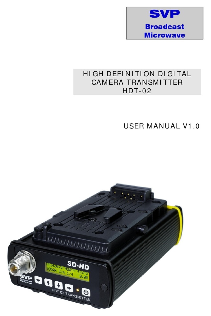
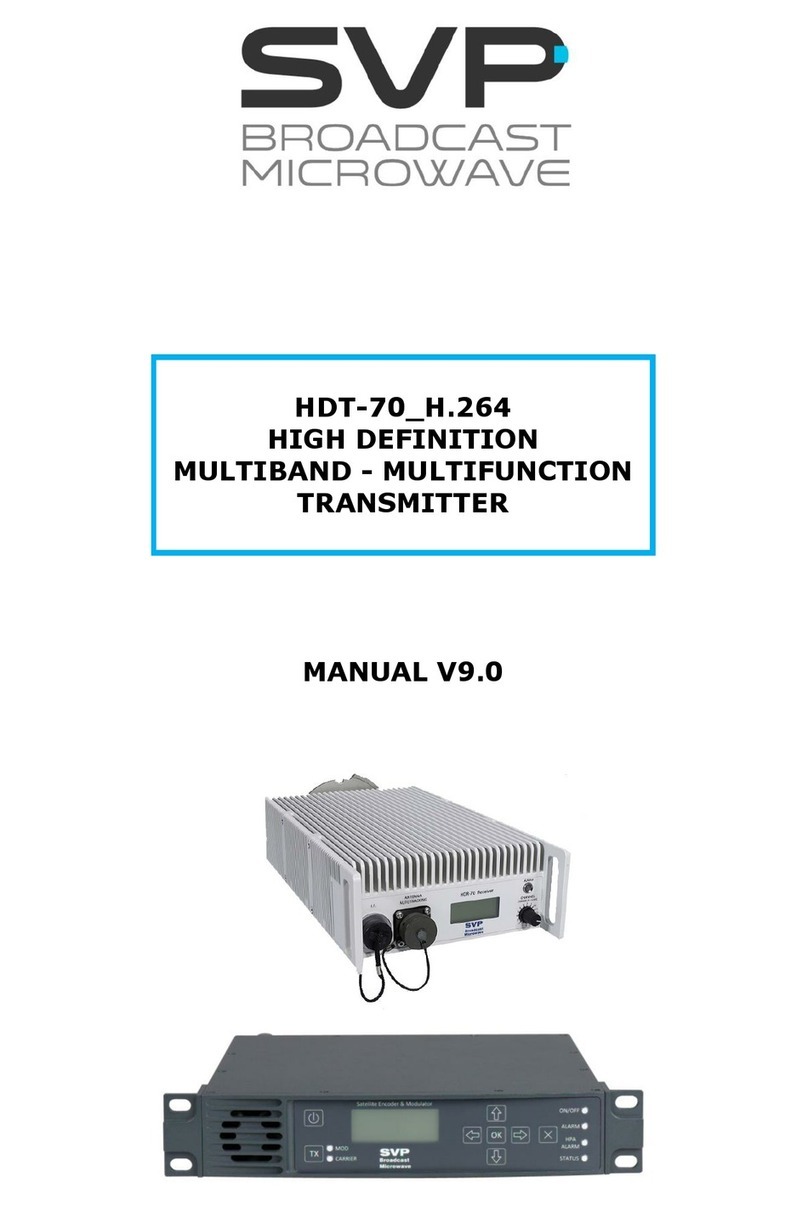
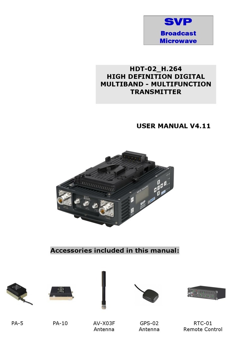
SVP DT-02 Series User manual

DT-02 Series COFDM
DIGITAL CAMERA
TRANSMITTER
USER’S MANUAL
SVP
Broadcast
Microwave

Preliminary pages
User’s Manual: DT-02 Series
i
Contents
Chapter 1: Introduction
The objective of this first part is to provide a general description of the DT-
02 series COFDM digital camera transmitter.
Chapter 2: Connections
This second part offers a detailed description of each of the connections on
the DT-02 series camera transmitter.
Chapter 3: Technical features
The objective of this chapter is to provide detailed technical features of the
DT-02 series camera transmitter: inputs, outputs, power supply, remote
control and physical and environmental characteristics.
Chapter 4: Front panel controls on the transmitter unit.
This chapter offers detailed descriptions of all controls on the front panel of
the equipment.
Chapter 5: Local control of the equipment
This chapter provides a detailed description of the local control procedures
for the DT-02 series transmitter, using the display and the keypad on front
panel of the equipment. Each of the menus and sub-menus are described in
detail, with the steps required to configure and monitor the unit’s
parameters.
Chapter 6: Applications
In this last chapter some interesting applications for the DT-02 equipment
are shown.

Preliminary pages
User’s Manual: DT-02 Series
ii

Preliminary pages
User’s Manual: DT-02 Series
iii
DEAR CUSTOMER:
We would like to thank you for selecting this equipment and welcome you to
the SVP’s growing family of products.
We are sure that the addition of this equipment to your existing installation
will cause you nothing but satisfaction.
Please read these instructions carefully, and keep them at hand in case you
have to refer to

Preliminary pages
User’s Manual: DT-02 Series
iv
IMPORTANT NOTES
1. The DT-02 series COFDM digital camera transmitter is completely
compatible with the DVB-T standard included in European Standard ETSI
EN300744.
2. DT-02 digital camera transmitter applies a MPEG2 compression to either
video or SDI input signal together with their corresponding 4 analogue
audio signals or digital embedded audio signals respectively. The
resulting signal is transmitted using COFDM modulation system.
3. The DT-02 transmitter operates in either in 2GHz or in 3GHz frequency
bands, from 2000 to 2500MHz, from 2200 to 2600MHz and from 3400 to
3700MHz respectively.
4. The equipment’s maximum output power is 100mw.
5. It is important to take special care in 2400 to 2500MHz band due to the
possible presence of Wi-Fi signals.
6. If second audio or data channel are not to be used in a transmission,
they should be disabled, in order to assign that bitrate to the video and
achieve a higher quality transmitted video signal.
7. TPS Settings:
a. QPSK: modulation scheme used in motion links, links with no
line of sight (NLOS) or when low signal level is achieved in the
receiver.
b. 16QAM: modulation scheme used for point to point links with
more than 16dB of MER of signal quality in the receiver.
c. 64QAM: modulation scheme used to transmit multiplexed
signals, in point to point links, line of sight, and high signal
level and more than 24dB of MER in the receiver.
8. It is not recommended to switch the equipment on without
antenna or load.

Contents
1Description ..................................................................................1
List of figures
Figure 1.1 DT-02 Camera transmitter ....................................................2
Figure 1.2 DT-02 Camera transmitter. Front view....................................3
Chapter 1
Introduction

Chapter 1: Introduction
User’s Manual: DT-02 Series
1
1Description
The DT-02 digital camera transmitter uses COFDM (Coded Orthogonal
Frequency Division Multiplexing) modulation system (2K mode), which
provides a superior signal robustness and a higher link performance. This
technology provides operators with efficient means to overcome the
challenges of NLOS propagation and mobile channels propagation
OFDM spread spectrum modulation system distributes the data over a large
number of closely-spaced carriers, 1705 carriers in 2K mode. The data are
divided into several parallel data streams, one for each carrier, so, each
carrier transports a lower data rate and the symbol duration is longer. Each
carrier is then modulated with a QPSK, 16QAM or 64QAM scheme.
An OFDM modulated signal, since uses a low symbol rate modulation
scheme (i.e. where the symbols are relatively long compared to the channel
time characteristics) suffer less from intersymbol interference caused by
multipath propagation. As the duration of each symbol is long, it is feasible
to insert a guard interval between the OFDM symbols, thus eliminating the
intersymbol and co-channel interference. So, if one carrier’s information is
lost, it would only be lost a small part of the whole information.
Besides, in OFDM, the sub-carrier frequencies are chosen so that the sub-
carriers are orthogonal to each other, meaning that cross-talk, interference,
between the sub-channels is eliminated. The orthogonality allows high
spectral efficiency.
On the other hand, OFDM system is invariably used in conjunction with
channel coding (forward error correction). The error correction code used in
this equipment is Reed-Solomon coding, which is concatenated with
convolutional coding, and there is and additional interleaving in between the
two layers of coding. Error correcting codes build redundancy into the
transmitted data stream. This redundancy allows bits that are in error or
even missing to be corrected in the receiver.
The reason why this combination of error correction coding is used is that
the Viterbi decoder used for convolutional decoding produces short error
bursts when there is a high concentration of errors, and Reed-Solomon
codes are inherently well-suited to correcting bursts of errors.
The European ETSI EN 300744 standard defines the following convolutional
coding rates: 1/2, 2/3; 3/4; 5/6, 7/8. There is a compromise between the
coding rate (signal robustness) and the transmitted bit rate. If the coding
rate in higher the signal transmission is more robust (1/2 is the most
robust) but the bit rate that the system is capable to transmit is lower.
Used modulation scheme of each OFDM sub-carrier, QPSK, 16QAM and
64QAM, is also connected with signal robustness and transmitted bit rate.
QPSK is the most robust and 64QAM is able to transport a higher bit rate.

Chapter 1: Introduction
User’s Manual: DT-02 Series
2
Besides the system can define 4 guard intervals: 1/4, 1/8, 1/16 and 1/32.
The guard interval it is used to reduce intersymbol interferences due to the
multipath propagation.
This equipment is very useful for a wide range of applications as ENG links,
COFDM signal transmissions from mobile vehicles as motorbikes,
helicopters, etc.
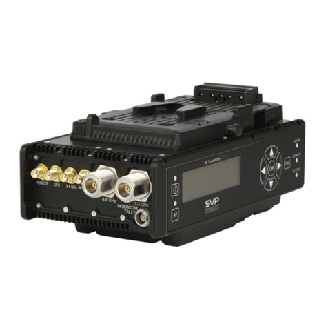
Figure 1.1 DT-02 Camera transmitter
DT-02 digital camera transmitter applies a MPEG2 compression to either
video or SDI input signal together with their corresponding 4 analogue
audio signals or digital embedded audio signals respectively. The resulting
signal is transmitted using COFDM modulation system, 2K mode.
The DT-02 camera transmitter has a DVB-ASI input, so it can be used as a
repeater.
Besides, this equipment can apply different video encoding formats
422P@ML, MP@ML (known as 4:2:0), standard delay (800ms) and super
low delay (80ms). In super low delay configurations the encoding mode is
4:2:0. The minimum latency of the equipment, using super low delay, is 2
frames.

Chapter 1: Introduction
User’s Manual: DT-02 Series
3
This camera transmitter has four independent analogue balanced audio
inputs. In all of them is independently selectable the input level, micro or
line.
The DT-02 transmitter operates in either in 2GHz or in 3GHz frequency
bands, from 2000 a 2500MHz, from 2200 to 2600MHz and from 3400 to
3700MHz respectively. This equipment’s maximum output power is 100mw.
The DT-02 equipment can be easily operated. In the front panel it has a
display and a keypad, which are used to configure the constellation scheme,
the forward error correction rate (FEC), the guard interval, and other
important and decisive parameters as transmission frequency and
transmission power. The equipment also offers the possibility to monitor the
transmission parameters set as well as presence/absence of alarms.
The DT-02 camera transmitter can also be controlled remotely via RS-232
connection. Transmitter’s most important parameters can be configured and
monitored.
The outstanding design, mechanical and electronic assembly makes this
very robust and reliable equipment. Besides, top quality components are
used, that is why a high quality transmission signal is achieved.
The equipment is fed with DC power supply from 10 to 36V.
Figure 1.2 DT-02 Camera transmitter. Front view

Chapter 2: Connections
Contents
1. Introduction.................................................................................5
2. Power Supply...............................................................................7
3. Video..........................................................................................8
4. Audio..........................................................................................8
5. DVB-ASI Transport Stream ............................................................8
6. Antenna ......................................................................................9
List of figures
Figure 1.1 DT-02 Camera transmitter’s connections.................................5
Figure 1.2 DT-02 Camera transmitter’s front panel..................................6
Figure 1.3 DT-02 Camera transmitter’s rear panel...................................6
Figure 2.1 DT-02 Battery connection .....................................................7
Figure 6.1 Transmitter antenna connection ............................................9
Chapter 2
Connections

Chapter 2: Connections
User’s Manual: DT-02 Series
5
1.Introduction
Every connection of DT-02 camera transmitter is on the rear panel, except
for the RF signal antenna connection that is on the front panel.
In chapter 3the features of each connection are explained.
With the equipment audio, video and power supply cables are supplied.
All the input/output connections of the camera transmitter are shown in the
figure below:
Figure 1.1 DT-02 Camera transmitter’s connections
The following figures show the DT-02’s front and rear panel. Connections
mentioned in the upper figure are shown below.

Chapter 2: Connections
User’s Manual: DT-02 Series
6
Figure 1.2 DT-02 Camera transmitter’s front panel
Figure 1.3 DT-02 Camera transmitter’s rear panel

Chapter 2: Connections
User’s Manual: DT-02 Series
7
2. Power Supply
The equipment is powered by a DC source from 10 to 36V. If the input
voltage of the equipment is out of that range, the LED of the equipment
blinks green and red showing an alarm Moreover, the equipment’s display
alternates the main screen with another that the power supply voltage is
shown blinking in the second line of the display.
The DC power supply is connected to the equipment via a 4 pin Lemo 1B
connector.
Figure 2.1 DT-02 Battery connection

Chapter 2: Connections
User’s Manual: DT-02 Series
8
3. Video
DT-02 equipment has two video inputs: analogue composite video input PAL
and digital video input SDI.
Both input signals use the same connector, 75Ωimpedance BNC located on
the rear panel. The same connector is used for the DVB-ASI transport
stream input.
In chapter 5, Local control of the equipment, it is explained in detail how to
choose the input video signal type (composite video PAL or digital SDI) that
has to be inserted to the equipment. It also explained how to introduce a
DVB-ASI Transport Stream signal.
SDI digital video input is compatible with SMPTE-259 Standard.
It is important that 75Ωconnectors are used. This is because the female
input connector of the DT-02 unit may be damaged and because an
impedance mismatch will occur.
4. Audio
The DT-02 has 4 analogue audio input signals that are inserted in pairs via
two 5pin Lemo 0B connectors on equipment’s rear panel. Only balanced
audio signals are accepted. Audio cables are supplied with the equipment.
Input audio signal level can be micro or line and it is selectable from the
front panel of the equipment.
The DT-02 also accepts four digital audio signals embedded on the SDI
video signal, which is compatible with SMPTE-272M standard.
5. DVB-ASI Transport Stream
The DT-02 also accepts a DVB-ASI transport stream input signal. This input
signal is introduced to the equipment through the analogue video and SDI
signal 75Ωimpedance BNC type insulated connector, located in equipment’s
rear panel.
The equipment also has a DVB-ASI transport stream detector, for the
equipment to know which signal type is being inserted to it.
In chapter 5, Local control of the equipment, it is explained in detail how to
choose the input video signal type to introduce a DVB-ASI Transport Stream
signal.

Chapter 2: Connections
User’s Manual: DT-02 Series
9
6.Data and Control
The DT-02 has a Lemo 0B 4 pin input connector used for either data
transmission or transmitter remote control. The transmitter can transmit
data at different bitrates or data direct from a GPS. The DT-02 can also be
controlled remotely by commands via RS-232 connection.
7.Antenna
The antenna is directly connected to the female N-type connector on the
front panel of the DT-02 camera transmitter.
Figure 7.1 Transmitter antenna connection

Contents
1Inputs .......................................................................................11
1.1SDI (Serial Digital Interface) ................................................... 11
1.2Composite video (PAL) ...........................................................11
1.3Analogue audios....................................................................12
1.4DVB-ASI Transport Stream .....................................................12
2Outputs .....................................................................................13
2.1RF (Antenna) ........................................................................13
3Power supply..............................................................................13
3.1DC Power supply ...................................................................13
4Physical characteristics ................................................................13
5Environmental conditions .............................................................14
List of tables
Table 1.1 SDI Input features..............................................................11
Table 1.2 Composite Video Input features ............................................ 11
Table 1.3 Audio input features............................................................12
Table 1.4 DVB-ASI transport stream input features ...............................12
Table 2.1 RF antenna output features..................................................13
Table 3.1 DC power supply features ....................................................13
Table 4.1 Physical characteristics........................................................13
Table 5.1 Environmental conditions.....................................................14
Chapter 3
Technical features

Chapter 3: Technical features
User’s Manual: DT-02 Series
11
1Inputs
1.1 SDI (Serial Digital Interface)
Table 1.1 SDI Input features
Item Feature
Connector label VIDEO/SDI/ASI
Connector type Insulated BNC female
Impedance 75Ω
Input level 800mVpp nominal ±10%
Return Loss > 15 dB, 5-270 MHz
Standard SMPTE-259M y SMPTE-272M
(there is the possibility to insert up to
four embedded audio channels)
Bit rate 270Mbit/s
Video encoding standard MPEG-2 (ISO/IEC 13818-2):
422P@ML
MP@ML (4:2:0)
Latency Standard (800ms)
Super low delay (80ms)
Aspect ratio 4/3
16/9
1.2 Composite video (PAL)
Table 1.2 Composite Video Input features
Item Feature
Connector label VIDEO/SDI/ASI
Connector type Insulated BNC female
Impedance 75Ω
Input level 1 Vpp over 75Ω
Return Loss >25dB @ 5 MHz
Standard PAL
Video encoding standard MPEG-2 (ISO/IEC 13818-2):
422P@ML
MP@ML (4:2:0)
Latency Standard (800ms)
Super low delay (80ms)
Aspect ratio 4/3
16/9

Chapter 3: Technical features
User’s Manual: DT-02 Series
12
1.3 Analogue audios
Table 1.3 Audio input features
Item Feature
Audio channel no. 4
Connectors label AUDIO 1
AUDIO 2
Audio connector 5 pint Lemo 0B type
Impedance 20KΩ
Sampling frequency 48 KHz
Bit rate 256 o 384 Kbit/s selectable
Encoding standard MPEG-1 L2
Signal to noise ratio >80dB
The pinout of the audio connector is:
Pin 3 => Ground
Pins 1 and 2 => Audio L signals
Pins 4 and 5 => Audio R signals
1.4 DVB-ASI Transport Stream
Table 1.4 DVB-ASI transport stream input features
Item Feature
Connector label VIDEO/SDI/ASI
Connector type Insulated BNC female
Impedance 75Ω
Standard EN50083-9
Maximum bit rate 31 Mbit/s

Chapter 3: Technical features
User’s Manual: DT-02 Series
13
2.1 RF (Antenna)
Table 2.1 RF antenna output features
Item Feature
Connector label RF ANTENNA
Connector type N female
Output frequency range 2.0 – 2.5 GHz
2,2 - 2,6 GHz
3,4 - 3,7 GHz
Impedance 50Ω
Output power 100 mWatt
Bandwidth 5, 6, 7 ó 8 MHz
Constellation scheme QPSK, 16QAM o 64QAM
Guard interval 1/4, 1/8, 1/16, 1/32
FEC 1/2, 2/3, 3/4, 5/6, 7/8
Transmission mode 2K
3.1 DC Power supply
Table 3.1 DC power supply features
Item Feature
Connector label POWER D.C.
Connector type 4 pin Lemo 1B
Input DC voltage 10-36 V.
Consumption 18Watt
The pinout of the power supply connector is:
1 and 2 pins => ground
3 and 4 pins => from 10 to 36V
Table 4.1 Physical characteristics
Item Feature
Width 110mm
Height 45 mm (without camera clip)
Depth 175mm
Weight 850gr (without camera clip)
2Outputs
3Power supply
4Physical characteristics

Chapter 3: Technical features
User’s Manual: DT-02 Series
14
Table 5.1 Environmental conditions
Item Feature
Operation temperature range From -10ºC to +55ºC
5Environmental conditions
Table of contents
Other SVP Transmitter manuals
Popular Transmitter manuals by other brands

WIKA
WIKA C-10 operating instructions

DAITEM
DAITEM 230-21X installation manual

SGM LEKTRA
SGM LEKTRA METER Technical documentation

RKI Instruments
RKI Instruments 65-2434RK Operator's manual

August
August DVB-T405 user manual

Flight Display Systems
Flight Display Systems MAN - FD900X5 Installation and operation manual