manuals.online logo
Brands
  1. Home
  2. •
  3. Brands
  4. •
  5. Bacharach
  6. •
  7. Transmitter
  8. •
  9. Bacharach MGS 550 User manual

Bacharach MGS 550 User manual

1: OPERATING AREA AND CONDITIONS
The Bacharach MGS-550 is an instrument for the
connuous monitoring of toxic and combusble gases,
oxygen and refrigerants in ambient air. The instrument
is housed in a rugged ABS or aluminum enclosure for
indoor and outdoor applicaons. The instrument can
be connected to a Bacharach monitoring system or a
Programmable Logic Controller (PLC). With the inte-
grated alarm relay configuraon, the instrument can
be operated as a stand-alone unit (with addional
local alarm signaling). The instrument is designed to
be installed in non-classified, non-hazardous, perma-
nent locaons.
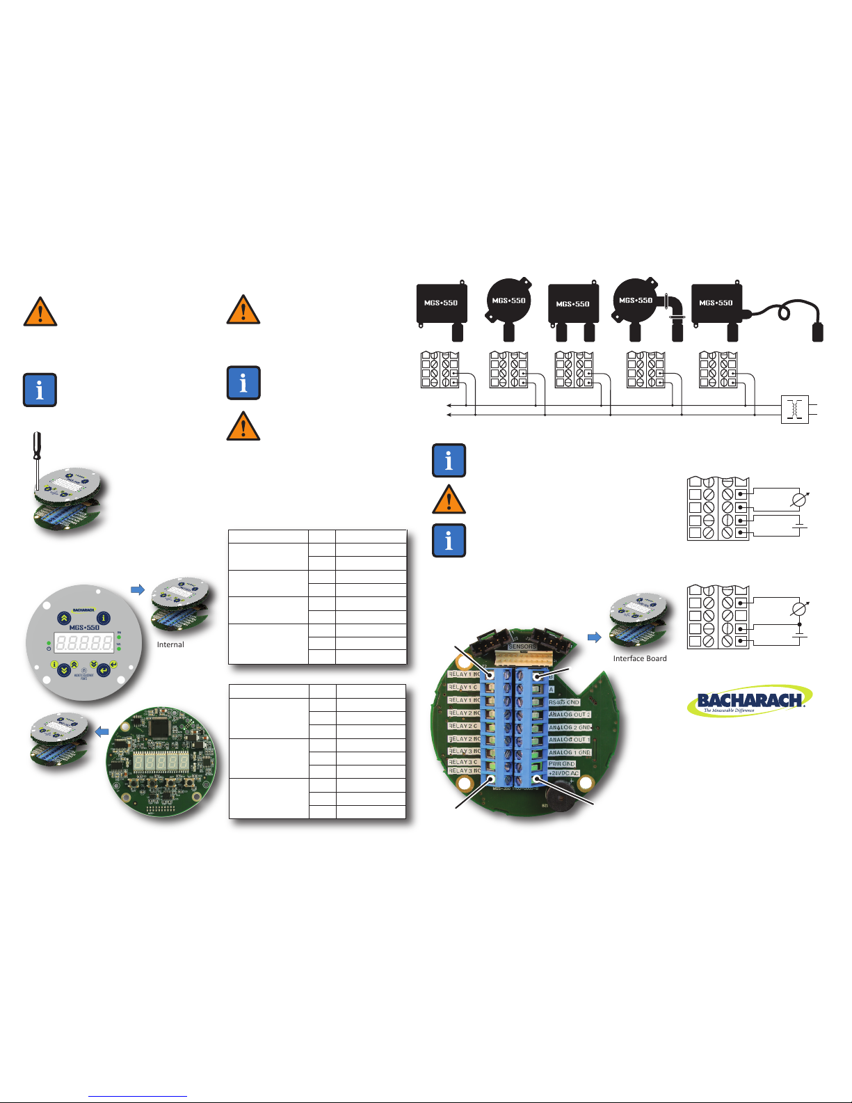
The instrument is powered by 19.5 to 28.5 VDC or
24 VAC (± 20%). The measured gas concentraon is
converted to a 4 to 20 mA, 0 to 5 V, 0 to 10 V, 1 to 5 V,
2 to 10 V analog and digital Modbus RTU output
signal. The instrument accepts wire sizes of 16 to
24 AWG (0.2 to 1.5 mm2).
P/N: 1100-0999
Revision 0
June 5, 2015
2: SAFETY INSTRUCTIONS
USER MANUAL: Before using this equipment, carefully read
and strictly follow the User Manual (part number
1100-1000). The user must fully understand and strictly
observe the instrucons. Use the equipment only for the
purposes listed and under the condions specified in that
document.
CODE COMPLIANCE: Comply with all local and naonal
laws, rules and regulaons associated with this equipment.
GENUINE PARTS: Use only genuine Bacharach spare parts
and accessories, otherwise proper funconing of the equip-
ment may be impaired.
FLAME PROOF AND EXPLOSION PROOF JOINTS: Joints of
the flame proof/explosion proof enclosure are not in accor-
dance with the relevant minimum or maximum values of
EN/IEC 60079-1. The joints are not intended to be re-worked
by the user.
EXPLOSIVE DIRECTIVES: As long as no EC-Type Examinaon
Cerficate per Annex II, clauses 1.5.5, 1.5.6 and 1.5.7 of
Direcve 94/9/EC exists: the measuring funcon of the gas
detecon transmier for explosion protecon, according to
Annex II, clauses 1.5.5, 1.5.6 and 1.5.7 of Direcve 94/9/EC
is not covered.
When using the product in areas subject to explosion
hazards, refer to the following:
● Instruments or components for use in explo-
sion-hazard areas which have been tested and
approved according to naonal, European or
internaonal Explosion Protecon Regulaons
may only be used under the condions specified
in the approval and with consideraon of the
relevant legal regulaons.
● The instruments or components may not be
modified in any manner. The use of faulty or
incomplete parts is forbidden. The appropriate
regulaons must be observed at all mes when
carrying out repairs on these instruments or
WARNING: Strictly follow the
instrucons in the User Manual
(part number 1100-1000).
CAUTION: DO NOT USE the MGS-550
in oxygen-enriched environments of
>21% oxygen. High “off-scale” read-
ings may indicate an explosive con-
centraon.
3: MOUNTING
ENVIRONMENTAL CONSIDERATIONS: Carefully consider the
full range of environmental condions to which the instru-
ments will be exposed.
TARGET GAS CONSIDERATIONS: The physical data of the gas
or vapor to be detected must be observed.
APPLICATION CONSIDERATIONS: The specifics of the appli-
caon (for example, possible leaks, air movement/dra, etc.)
must be observed.
ACCESSIBILITY CONSIDERATIONS: The degree of accessibili-
ty required for maintenance purposes must be granted.
ACCESSORY CONSIDERATIONS: The types of oponal and
accessory equipment that will be used with the system must
be kept in mind.
SENSOR POSITIONING: When installing the instrument or
the remote sensor, the sensor opening should always be
poinng downward.
SUN SHIELD CONSIDERATIONS: If the instrument is exposed
to direct sunlight, the use of a sunshield is recommended.
4: WEIGHTS AND DIMENSIONS (APPROXIMATE)
FULL-SIZE
MOUNTING
TEMPLATES --
DO NOT
RESCALE
115.0 mm (4.53 in)
120.6 mm (4.75 in)
Mounng
Point (ABS)
Mounng
Point (ABS)
Mounng
Point
(Ex d)
Mounng
Point (Ex d)
144.1 mm (5.67 in)
IP66-Rated ABS Enclosure
with Local
Sensor
Flame
Proof/
Explosion
Proof Ex d
Enclosure
with Local
Sensor
Magnec
Wand
COMPONENT WIDTH HEIGHT DEPTH
mm in mm in mm in
General Purpose Enclosure
Explosion Proof Encosure
210
125
8.3
4.9
225
190
8.9
7.5
85
90
3.4
3.5
kg lbs
1
1.6
2
3.5
WEIGHT
World Headquarters
621 Hunt Valley Circle
New Kensington, PA 15068 USA
Phone: 724-334-5000 • Fax: 724-334-5001
Toll Free: 1-800-736-4666
Website: www.MyBacharach.com
E-mail: [email protected]
5: WIRING
1: Strip 0.2 to 0.25 inches (5 to 7 mm) of wiring
insulaon.
2: Connect the wires as indicated.
RELAY 1 NC
RELAY 1 C
RELAY 1 NO
RELAY 2 NC
RELAY 2 C
RELAY 2 NO
RELAY 3 NC
RELAY 3 C
RELAY 3 NO
10
11
12
13
14
15
16
17
18
Relay 1 Output
Relay 2 Output
Relay 3 Output
FUNCTION PIN LABEL
SHIELD WIRE WARNING: Con-
nect the shield of the power
wires to the earth ground of the
central control system (e.g.,
chassis, ground bus bar, etc.). NOTE: For connecons to an external controller
such as a Bacharach MGS or GDA, refer to the
manual that was included with the controller.
NOTE: For 24 VDC installaons,
the input is protected. If the
polarity is reversed, the instru-
ment will not power-up.
POLARITY WARNING: For 24 VAC installaons
in a daisy-chain configuraon, the neutral polari-
ty must be maintained for all instruments.
WARNING: The MGS-550 must be
powered by either (a) a suitable UL
60950/CSA cerfied power supply
that is isolated from line voltage by
double insulaon, or (b) an appro-
priately rated UL listed/CSA Class 2
transformer. Failure to comply can
result in personal injury or death.
M20 OPENINGS: The ABS and the
flame proof/explosion proof enclosures
provide four M20 openings for cable
glands or plugs. These openings can be
used for field wiring, direct aachment
of a sensor or wiring of a remote sensor.
Unused openings must be closed with a
suitable plug and gasket, maintaining
the IP or Ex d rang.
114A Georges Street Lower
Dun Laoghaire • Co Dublin • Ireland
Phone: +353 1 284 6388 • Fax: +353 1 284 6389
PIN 10
PIN 18
PIN 9
PIN 1
Connector Style
May Vary Slightly
from Photo
NOTE: To make wiring connecons,
you must first open the MGS-550
housing. The enclosure lid of the
IP66 ABS housing has four capve
screws. The enclosure lid of the Ex d
(flame proof/explosion proof) hous-
ing unscrews.
Next, carefully discon-
nect the combinaon
Display Bezel and
Processor Board (which
remain connected)
from the lower Inter-
face Board by unscrew-
ing the 3 capve
screws. Access the
capve screws through
holes in the Display
Bezel.
Internal
Display Bezel
(Top Layer)
Processor
Board
(Middle Layer)
with Keyed
Ribbon Cable
Interface Board
(Boom Layer)
NOTE: Aer wiring is completed, carefully re-as-
semble the enclosure and its components, nong
the keyed ribbon cable and sensor connectors.
Aer installaon is complete, be sure to refer to
the User Manual (part number 1100-1000) for
detailed instrucons on registering the sensors and
configuring the MGS-550 for proper operaon.
PWR
GND
24VAC
PWR GND
24VAC
AC
POWER
PWR
GND
24VAC
PWR
GND
24VAC
PWR
GND
24VAC
PWR
GND
24VAC
PWR GND
24VAC
SUPPLY
TRANSFORMER
4-Wire Power and Output to
Central Control System
3-Wire Power and Output to
Central Control System
mA
A OUT 1
A1 GND
PWR GND
+24VDC
-
+
mA
A OUT 1
PWR GND
+24VDC
-
+
Refer to the User Manual (part number 1100-1000)
for detailed instrucons on accessing the internal
components for wiring.
+24VDC/AC
PWR GND
ANALOG 1 GND
ANALOG OUT 1
ANALOG 2 GND
ANALOG OUT 2
RS-485 GND
A
B
1
2
3
4
5
6
7
8
9
Power
(+24VDC or 24VAC)
Analog Output 1
Analog Output 2
Modbus RTU
FUNCTION PIN LABEL

Other manuals for MGS 550

5

Other Bacharach Transmitter manuals

Bacharach GDX-350 User manual

Bacharach

Bacharach GDX-350 User manual

Bacharach GDX-350 User manual

Bacharach

Bacharach GDX-350 User manual

Bacharach MGS 550 User manual

Bacharach

Bacharach MGS 550 User manual

Bacharach GDX-150 User manual

Bacharach

Bacharach GDX-150 User manual

Popular Transmitter manuals by other brands

Emerson Rosemount 3051S Series quick start guide

Emerson

Emerson Rosemount 3051S Series quick start guide

Ebyte E32-DTU user manual

Ebyte

Ebyte E32-DTU user manual

Brasch BGS-ND-TRNS Installation, operating and maintenance instructions

Brasch

Brasch BGS-ND-TRNS Installation, operating and maintenance instructions

SEBA KMT Sebalog GT-3-1 user manual

SEBA

SEBA KMT Sebalog GT-3-1 user manual

LoRa Alliance MCF-LW13MIO manual

LoRa Alliance

LoRa Alliance MCF-LW13MIO manual

Axcera Innovator LX Series instruction manual

Axcera

Axcera Innovator LX Series instruction manual

mXion PZB-T user manual

mXion

mXion PZB-T user manual

Multi-code 4140 installation instructions

Multi-code

Multi-code 4140 installation instructions

MuxLab 500052 Quick installation guide

MuxLab

MuxLab 500052 Quick installation guide

Danfoss T70 2 user manual

Danfoss

Danfoss T70 2 user manual

Siemens Sitrans LR200 Quick start manual

Siemens

Siemens Sitrans LR200 Quick start manual

Bosch RADION RFUN-A installation manual

Bosch

Bosch RADION RFUN-A installation manual

BURK Technology PlusConnect Installation and operation manual

BURK Technology

BURK Technology PlusConnect Installation and operation manual

Ramsey Electronics RRW1A user manual

Ramsey Electronics

Ramsey Electronics RRW1A user manual

MODSTER Vector SR48 user manual

MODSTER

MODSTER Vector SR48 user manual

Endress+Hauser Proline 300 Brief operating instructions

Endress+Hauser

Endress+Hauser Proline 300 Brief operating instructions

Rosslare SA-26 installation instructions

Rosslare

Rosslare SA-26 installation instructions

Winters LM6 Installation and operating manual

Winters

Winters LM6 Installation and operating manual

manuals.online logo
manuals.online logoBrands
  • About & Mission
  • Contact us
  • Privacy Policy
  • Terms and Conditions

Copyright 2025 Manuals.Online. All Rights Reserved.