GP:50 311 User manual

A5CS-311.00 Rev B
Pressure, Level & Temperature Transmitters & Transducers
Model 311
Hazardous Approved Products
TABLE OF CONTENTS
1. Introduction
Product Description
Warning
Unpacking/Inspection
Using this manual
2. Installation
Mounting/process connection
Power Supply
Wiring/Grounding
Environment
3. Operation/Maintenance/Handling
4. Trouble Shooting/Return Information
5. Warranty
6. Appendix A – Specs
Specs (performance/physical)
Part number configuration
Available accessories
7. Appendix B – Approval info
C of C’s / D of C’s
INSTALLATION MANUAL
INSTALLATION MANUAL
www.GlobalTestSupply.com
Find Quality Products Online at: sales@GlobalTestSupply.com

Disclaimer: No representations or warranties are made with respect to the contents of this Installation Guide. GP:50 reserves the right to revise this guide
and to make changes periodically to the content hereof, without obligation to notify any persons of such revisions.
1. INTRODUCTION
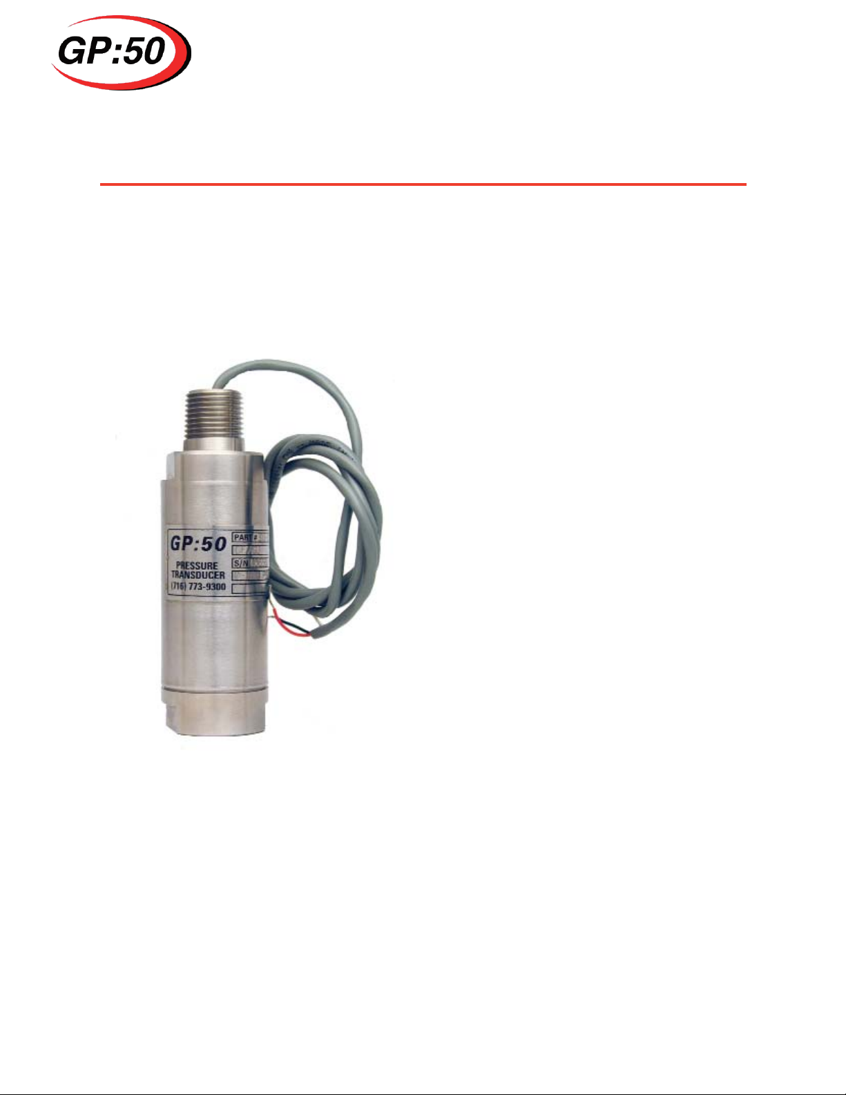
1.1 Product Description
The Model 311 is an oil field service pressure transmitter with a ¼”NPT(F) pressure port fitting (standard -
optional ports available), 4-20 mA output and measures pressures up to 75,000 psi (5168 bar).
1.2 Warning
Pressurized vessels and associated equipment are potentially dangerous. The product described
in the guide should be operated only by personnel trained in the procedures that will assure safety to
themselves, to others, to the equipment, and to the product. Specific warnings are noted as
in specific installation/operation sections.
1.3 Unpacking and Inspection
The Model 311 was carefully tested, inspected and packed. Upon receipt of the shipment thoroughly
inspect the transducer. If you see any visible signs of obvious shipping damage, notify the freight
company immediately.
1.4 Using this manual
This manual is intended to help the end user install, maintain, and provide general service of the GP:50
Model 311 pressure transmitter. The user should have a general understanding of current loops & gen-
eral instrument control. The Model 311 is a precision instrument and should be given the same care as
any other precision instrument during installation and operation.
INSTALLATION
1.5 Mounting/Process Connection
The standard Model 311 transducer is supplied with a ¼” NPT(F) pressure port. Installation of the device
shall be in accordance with industry standard pipe fitting requirements for this size .Torque shall only be
applied to the transducer during installation (or removal) from the wrench flats provided on the pressure
port. As a general rule of thumb, the device shall be torqued “wrench-tight” to preclude leakage from the
process connection. Contact GP:50 sales personnel for additional information if required, or for specific
installation requirements for non-standard process connections.
Insure media is compatible with 15-5 SST (standard material, optional materials available, check part
number (Appendix A) to verify wetted material) to avoid premature corrosion of the diaphragm. This can
cause performance degradation and eventual sensor rupture/failure.
Properly tighten process connections before applying pressure to insure no leaks or mechanical failure
can occur.
Never insert sharp objects into diaphragm. This could cause permanent damage the sensor and / or
mechanical failure/diaphragm rupture.
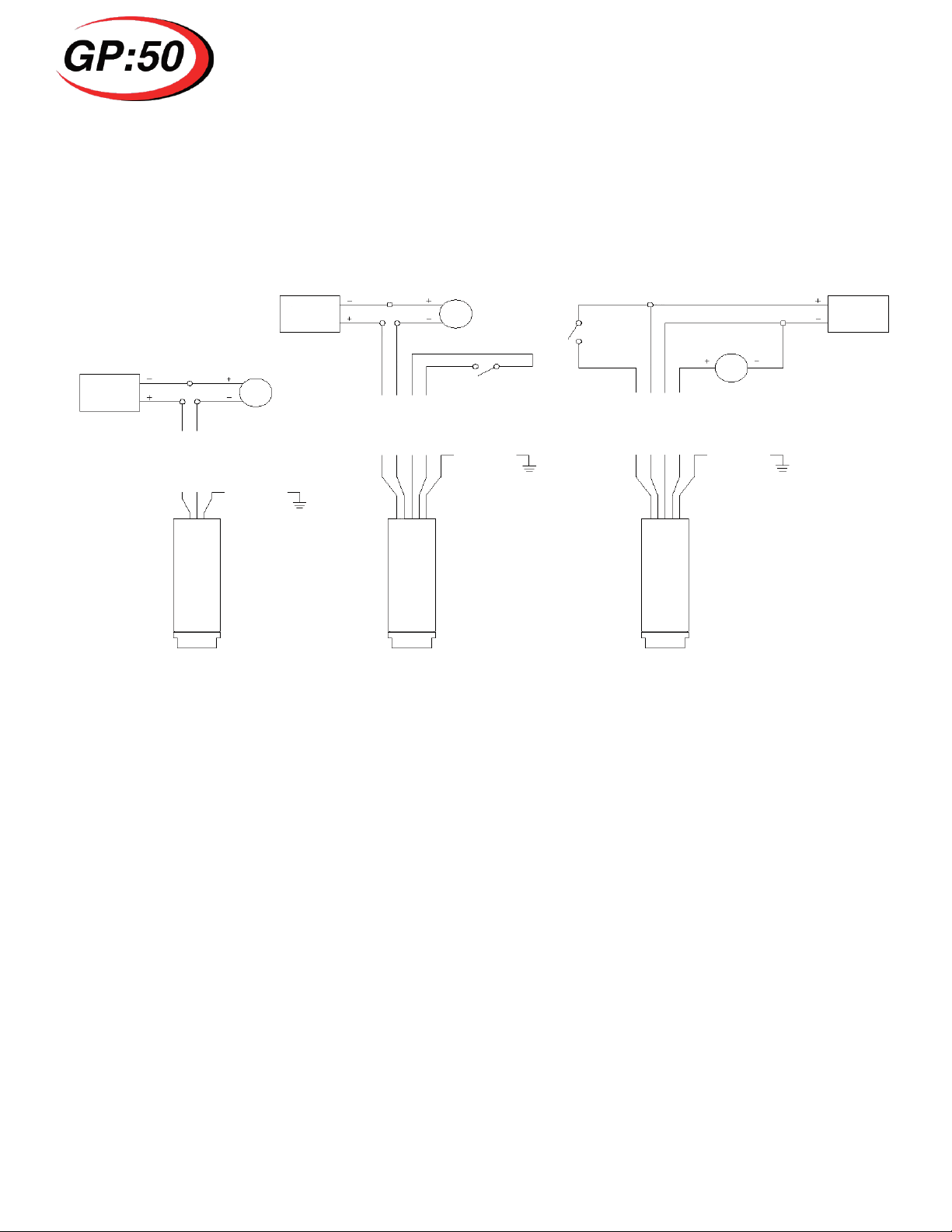
1.6 Power Supply Connection
For best operation the pressure transmitter needs clean, regulated power with an output impedanance
less than 20 ohms. Minimum voltage is 10 volts with no resistive loading, to a maximum of 36 Vdc
(Z, P + X Series) (28 Vdc for I, AI + GI Series units). As loads are added to the current loop (galvanic bar
riers, current measuring devices resistors), the minimum excitation voltage must increase in order to
maintain proper operating voltage.
Exceeding maximum supply voltage can damage electronics and cause malfunctions or failure. With In-
trinsically Safe units, this can cause an explosion. Please refer to the attached IS connection diagram
(Appendix B), and applicable local codes, for proper electrical installation.
Always inspect/clean electrical connection and sealing surface prior to installation.
Δ
!
Δ
!
Δ
!
Δ
!
Δ
!
www.GlobalTestSupply.com
Find Quality Products Online at: sales@GlobalTestSupply.com

Pressure, Level & Temperature Transmitters & Transducers
1.7 Wiring/Grounding
Wire per Fig. 1 connection diagrams for standard wiring or specific shunt option. Do not run wires next to
power lines, electrical systems, motors, generators, or any other equipment which may generate a signifi-
cant amount of electrical noise or magnetic fields.
Fig. 1: Connection Diagrams (for IS units see Appendix B)
POWER
SUPPLY
POWER
SUPPLY
POWER
SUPPLY
4-20m A
METER
4-20m A
METER
4-20m A
METER
A
A
A
CASE/GND
CASE/GND
CASE/GND
NON-POWERED SHUNT
(OPTION NC)
NO SHUNT
(STANDARD)
POWERED SHUNT
(OPTION NB)
SEE
NOTE 2
SEE
NOTE 2
+EXC/SIG
-EXC/SIG
+EXC/SIG
-EXC/SIG
SHUNT/CAL
SHUNT/CAL
+SHUNT/CAL
+EXC/SIG
-SHUNT/CAL
-EXC/SIG
NOTE 1: QUALIFIED END-USER TO INSTALL GROUND WIRE PER CODE REQUIREMENTS.
NOTE 2: SHORT WIRES TOGETHER OR CLOSE SHUNT SWITCH (SUPPLIED BY END USER)
TO ACTIVATE SHUNT.
Install only after verifying both input power and line pressure are off and at zero.
Avoid contact with exposed leads or connector pins, high voltage may be present on leads and can cause
electrical shock.
Observe safe ESD handling precautions to avoid static damage to sensitive components.
1.8 Environment
The typical operating temperature range for the electronics is from -40°F (-23°C) to 185°F (85°C). The
unit should be mounted as close to the process as possible with the ambient temperature surrounding the
electronics in the range as specified above.
Exceeding maximum temperature rating can cause electronics malfunction or failure, with IS units, an ex
plosion risk.
Protect electrical connection from direct/continued exposure to fluids. Moisture ingress can occur and
cause eventual electrical failure.
Δ
!
Δ
!
Δ
!
Δ
!
Δ
!
www.GlobalTestSupply.com
Find Quality Products Online at: sales@GlobalTestSupply.com

Pressure, Level & Temperature Transmitters & Transducers
OPERATION/MAINTENANCE/HANDLING
The Model 311 is designed to give a 4-20 mA output directly proportional to pressure. Specific pressure
range, input voltage requirements and electrical connections are marked on unit. See Appendix A for all
performance specifications. Standard electrical connection is a HEYCO connector on the I.S. approved
product +½” NPT M on Explosion Proof Series and pressure port is ¼” NPT(F). Appropriate mating con
nections are required for proper installation and safety. Other port and electrical connections are available
and noted as option code in part number. See Appendix A for list of options.
Replace broken fasteners (available through the factory) as they may compromise the seal and cause
contamination and/or electronics failure.
Unit can be hot when removed from service. Wear protective gloves when handling unit in this condition.
Δ
!
Δ
!
TROUBLESHOOTING/RETURN INFORMATION
No output
- Verify power supply voltage meets transmitter requirements
- Check wiring connections
- Verify pressure if being applied
- Verify output load is not shorted
Erratic output or zero drift
- Verify pressure applied is constant
- Verify power supply remains within specifications
- Inspect electrical connections for discontinuity or damage
- Verify output with a multi-meter
- Check insulation resistance between amplifier and transmitter case
Slow Response
- Verify pressure port is not clogged
If the problem persists, please call the factory as indicated below for assistance Have the following infor
mation ready:
- Serial number
- Model number
- Loop setup – power supply, resistor, cable routing/length
- What action caused devices to fail?
Contact: [email protected]
716-773-9300
Repairs should only be done by GP:50. Repairs done by customer will void any warranties and may
cause permanent damage to unit. Repairs done by customer on Intrinsically Safe units will void the
approvals and are a potential explosion hazard.
Returned products that have been exposed to hazardous substances should be cleaned prior to return
and should include the Material Safety Data Sheet for all substances.
Δ
!
Δ
!
www.GlobalTestSupply.com
Find Quality Products Online at: sales@GlobalTestSupply.com

Pressure, Level & Temperature Transmitters & Transducers
Contact our website http://www. GP50.com for a copy of our repair policy or call our repair dept.
WECO® is a Federally Registered Trademark with FMC Technologies.
Copyright© 2005 GP:50
All rights reserved. This specification must not be reproduced in any form without written permission of the copy-
right owner.
Accuracy - RSS [Non-linearity (terminal),
Hysteresis, Repeatability]
Option B: + 0.5% FSO
Option C: + 0.2% FSO
Option D: + 0.1% FSO
Zero Balance 4.0 mA ± 1% FSO at 70°F (21°C) and 24 Vdc
Full Scale Output 20 mA ± 1.0 % FSO at 70°F (21°C) and 24 Vdc
Compensated Temperature Limits 0°F to 180°F (-18°C to 82°C )
Operating Temperature Limits -40°F to 185°F (-40°C to 85°C)
Temperature Compensation - Zero Less than ± 1.0 % FSO/100°F
Temperature Compensation - Span Less than ± 1.0 % FSO/100°F
Excitation Voltage 10-36 Vdc (10-28 Vdc for I/AI/GI approvals)
Input Current 23 mA max
Output Current 23 mA max
Load Impedance N/A
Proof Pressure: <15K / >15K 2X FSPR (22.5K psi max) / 1.2X FSPR
Burst Pressure: <15K / >15K 5X FSPR 923K psi max) / 1.5X FSPR
Sensor Material 316 & 15-5PH SST
Housing Material 304 SST
Pressure Connection ¼”NPT(F) standard, see option codes for other pressure connections
Electrical Connection HEYCO w/36” cable - I.S. units, ½” NPT M-Explosion Proof
Identification Etched onto housing or nameplate
APPENDIX A - SPECS
1.9 Specifications
5 WARRANTY
GP:50 warrants its products to the original customer/purchaser against defects in material and workman
ship for a period of one (1) year from the date of delivery by GP:50, as shown in its shipping documents,
subject to the following terms and conditions:
Without charge GP:50 will repair or replace products found to be defective in materials or workmanship
within the warranty period provided that:
1. The product has not been subjected to abuse, neglect, accident, incorrect wiring (not provided by
GP:50), improper installation or servicing, or use in violation of instructions furnished by GP:50.
2. As to any prior defect in materials or workmanship covered by this warranty, the product has not
been repaired or altered by anyone except GP:50 or its authorized service agencies.
3. The serial number has not been removed, defaced or otherwise changed.
4. Examination discloses, in the judgement of GP:50, a defect in materials or workmanship which de-
veloped under normal installation, use and service; and
5. GP:50 is notified in advance of, and approves, the return by issuing a Return Material Authorization
Number; and the products are returned to GP:50 transportation prepaid. Products returned without
an RMA number will not be accepted and be returned to sender at sender’s expense.
THIS WARRANTY IS THE ONLY WARRANTY AND IS IN LIEU OF ANY OTHER WARRANTY EXPRESSED OR IMPLIED, INCLUDING ANY
WARRANTY OR MERCHANTABILITY OR FITNESS. NO REPRESENTATIVE OR PERSONS ARE AUTHORIZED TO GIVE ANY OTHER WAR-
RANTY OR TO ASSUME FOR GP:50 ANY OTHER LIABILITY IN CONNECTION WITH THE SALE OF ITS PRODUCTS. GP:50 DOES NOT
ASSUME THE COSTS OF REMOVAL AND/OR INSTALLATION OF THE PRODUCT OR ANY OTHER WORKMANSHIP, OR WILL GP:50 BE
LIABLE FOR ANY CONSEQUENTIAL DAMAGES RESULTING FROM THE USE OR INSALLATION OF ITS PRODUCT.
www.GlobalTestSupply.com
Find Quality Products Online at: sales@GlobalTestSupply.com

www.GlobalTestSupply.com
Find Quality Products Online at: sales@GlobalTestSupply.com
Table of contents
Popular Transmitter manuals by other brands

CRC
CRC Codar AT.5 instruction manual

FrSky
FrSky DHT-U instruction manual

Meinberg
Meinberg DCF77 PCI511 operating instructions

BD Sensors
BD Sensors DMP 303 operating manual

Teledyne Analytical Instruments
Teledyne Analytical Instruments INSTA TRANS-XD operating instructions

WIKA
WIKA T12 Series operating instructions