Svpribor Irk-Pro gamma User manual

1
Insrtruction Manual
SVPRIBOR
IRK-PRO gamma
Tver Russia

2
THE GENERAL INFORMATION
PURPOSE AND FUNCTIONALITIES
TDR:
To define the distance to place of wave impedance changing for all cable types:
defaults, splices, length, cross - effects, split location.
To mute in high – intensity noise environment. Trace stabilization.
DSP TDR:
To work with a long and problem cable.
Have a logarithmic scale. That allows checking all cable without gaining.
Positioning of measuring cursors on maximum (minimum) value.
Bridge:
Measuring the distance to place of cable insulation reducing.
Definition of the open-cable or wire reversing location.
Measuring of insulation resistance, loop, ohmic disbalance, electrical capacity of all
cable types.
Color TFT display 800x480.
Multifunctional menu.
PC communication through USB or IRDA.
EXPLOITATION CONDITION
Operational Temperature from -20 to +50ºC
Relative humidity to 90% at 30ºC
Atmospheric pressure from 86 to 106 kPa
CERTIFICATES
The state register №17719-07. the certificate on the statement of measurement device type
RU.C.34.001.A №27301.
TECHNIQUES
TDR
Range of measuring
131, 262, 523, 1046, 2093, 4186,
8371, 16742, 33485, 66970,
133939m
Maximal resolution 0,2 m
Overlapping attenuation Not less 80 dB
Adjusted amplitude of measuring pulse 6 – 18 V with step 1 V
Measuring pulse duration 16 ÷50000 ns
Number of averaging 2, 4, 8, 16, 32, 64, 128, 256, 512
Range of VF (Velocity Factor ) or CC10,143÷1 with step 0,001
1. CC=1/VF

3
Measuring bridge IRK-PRO
Range of insulation resistance measuring 1 kOhm ÷50000 MOhm
Range of electrical capacity measuring 0,1 ÷2000 nF
Range of loop resistance measuring 0 ÷10 kOhm
Test voltage 180, 400 V
Range R leakage in the place of insulation
damage
0 ÷20 MOhm
Range of voltage measuring 0 – 300 V
Maximal error of distance defining to the place
of insulation damage
for R leakage = 0 ÷3 MOhm
0,1%+1m
Maximal error of loop resistance measuring in
the range
0 ÷3000 Ohm 0,1%+1 LSU
3 kOhm ÷10 kOhm 0,1 kOhm
Maximal error of ohmic disbalance measuring 0,1%+1 LSU
Maximal error of insulation resistance
measuring
In the range 0÷999 kOhm
In the range 1МОм÷999 MOhm
In the range 1000МОм÷4999 MOhm
In the range 5000МОм÷10000 MOhm
In the range >10000 MOhm
2%+1 LSU
2%+1 LSU
5%+1 LSU
10% +1 LSU
TBD
Maximal error of electrical capacity measuring 2%+1 LSU
LSU – displayed Least Significant Unit
General parameters
Power source 6 type СNiMh
Consumption power not more 7 W
Dimensions (mm) 270х240х120
Weight 2,5 kg
PACKING LIST
№Name Quantity
1 The device IRK-PRO GAMMA 1
2 Set of wires 1
3 Accumulator 1
4 AC adapter
5 Instruction Manual 1

4
FRONT PANEL
On the front panel are placed the control knob and the following sockets:
«15 V» Socket for connection of an external feed
Z0Potentiometer of a match installation
«Rx/Tx» Input\Output. Measuring pulse generator output and TDR input
in a combined mode
«A», «B», «C» Sockets for Bridge measuring wires of IRK-PRO
IrDA Window to maintenance of infrared PC communication
«Tx» Measuring pulse generator output in a separated operating
mode.
USB for PC communication

5
Front panel keys:
The key to turn ON/OFF a power
÷Functional keys.
Help key
▲▼ ◄►
Navigating keys are moves on the screen; the [OK] key starts the
chosen item.
÷Keys to input a figure information
Main Menu key
The key to turn on (of) of a full-screen mode. In this mode the
purpose of functional buttons is not displayed.
TURNING ON THE DEVICE
To turn on the device press the key on the front panel. To turn off the device press
again.
POWERED OF THE DEVICE
Powered of the device is fulfill by 6 accumulators type C NiMh, automotive power or by
adaptor from AC network.
During the powered by adaptor the accumulator is charges quickly. You can charge the
accumulator then the device is turned on or off. In any case the time of total accumulators
charging doe not exceed 3 hours.
The controlling of the residual charge is realize according to displayed accumulators icon.
Notice:
Turning on the illumination reduces the accumulators operating time without
additional charging.

6
MAIN MENU
To view a Main Menu – turn ON the device or press the key in the working mode. To run
the menu item – press the [ОК] key.
«TDR», «DSP TDR» and «Bridge measurements» - are the measurement functionalities,
described bellow.

7
TDR
The classic pulse TDR is used to define a distance to the place of wave resistance changing for
all cable types.
The devise can be used to:
Measurement of distance to place of cable fault;
Definition of fault type;
Measurement of distance between heterogeneity of wave resistance;
Definition of a cable length;
Measurement of VF (or CC).
PRINCIPLE OF WORK
The principle of the device work is based on the known physical phenomenon of reflecting of
voltage measuring pulse from heterogeneity of wave resistance of an investigated cable. Thus
the fault locate can be calculated from the time between the moment of the measuring pulse
beginning and the moment of reflected pulse acceptance, if propagation velocity in lines is
known. The propagation velocity for reflectometry is traditionally designated by VF
VF=V/C alwais VF <1
or
CC: CC=1/VF flwais CC>1
Here is C - velocity of light in vacuum, V - propagation velocity of an electromagnetic wave in
an investigated cable. For the most cable type the VF is vary from 1÷3.
The type of fault can be defined from the form of reflected pulse. Thus on the pulse form are
influence the loss and a dispersion of a cable. On enough long or much faulted cables the
reflected signal can be very loosed. In the device there is the opportunity of preliminary echo
gaining.
The device connected to a cable is heterogeneity too. To eliminate a parasitic echo-signal use
the controlled load MATCH. Rotating a potentiometer [MATCH] it is possible to achieve a
significant loss of repeated reflections. Necessity of the match is most actual for short lines.
The device can work in two modes: with the united and separated outputs for applying of the
measuring pulse and supervision of the reflected signal.
The mode with the united input/output is most often used. You can locate the most of
heterogeneity from observable trace.
To achieve the maximal performance it is necessary to connect the device to pair. The channel
“wire-screen” have a great loss factor and a level of noise. Any of heterogeneity of a line causes
a loss increasing and limiting distance reducing. On short distances it is necessary to use a
short pulses, on greater - longer. The device setup itself the optimum pulse width depending on
the chosen range. However you can operatively change this parameter for reception of more
precise picture.
In a mode of separate inputs the measuring pulse is transferred in a line through a socket [INPUT/
OUTPUT]. The reflected signal is enter the device through other socket [INPUT]. In this mode

8
the estimation of contact influence of the line in which the measuring pulse o n other line in
which the induced signal is observed is got is possible. Also this mode is useful for searching
of wire reversing location (split). The pulse is propagate in the line and reaches a wire reversing
location, which is characterized by a sharp increasing of electromagnetic communication
between the pairs. As a result you can see a characteristic signal on the reflectogram.
There is new algorithm of muting. During the intense noises it is recommended to turn on the
muting mode. To rise of the trace stability is applied the averaging mode. Growth of averaging
number is cause e stability rising and reducing of the display refreshing speed.
TURNING ON THE TDR
Preliminary choose a cable in Main Menu. The device will adjust on the selected cable
gauges.
If you does not choose a cable – the device will adjust on default cable gauges.
After connect the device to a line through a socket [Rx/Tx] by the measuring cable. Connect a
red cable to a test line. Black wire of cable is standby for frequency measurements (it does not
use during the TDR operating).
TRACE VIEWING

9
There are two cursors on the TDR screen, between them the distance is measured on the trace.
To make a cursor an active – press the ◄► keys. To vertical move a trace – press the ▲▼
key.
To operate with the trace gauges use the following keys: [PULSE], [RANGE],
[AMPLIFICATION]. At setting the viewing range the device select itself he measuring pulse
width. The [STRETCHING] key is used to view the detail trace around an active cursor (ZOOM).
The [MAP] key is used to view the whole cable. The [AVERAGING] key is used to eliminate
the occasional noises and to rice picture stability during the increasing the averaging.
The keys on the left vertical part of the menu are changing the TDR working mode: trace
recording [RFG storage], [SCREEN] - activation of the logged trace for the comparison [+
memory]; [INPUTS] - work in separate or common mode; [AMPLITUDE] - adjusted pulse
amplitude, [DENOISE] - the mode of wavelet smoothing for a line with intensive noise.
INSTALLATION FOR ADISTANCE MEASUREMENT
If you does not choose the cable and work with default cable - it is necessary to establish VF (or
CC) and a range of a cable viewing. The distance between cursors will be calculated according
to VF in selected view range.
If the VF is unknown, the device will establish it on a Cable Type. For this purpose select e
necessary mark in Main Men \ Cable selection \ Cable Type.
MEASUREMENT OF THE DISTANCE
Measurement of the distance must be made after setting of VF (or CC) or selecting of a cable
from the List.
Measurement of distance is always carried out between two cursors. For measurement of the
distance from the cable beginning to heterogeneity it is necessary a to make a zero cursor
become an active. Above the zero cursor there should be a label. If there is no label, press
[ОК] - and label will appear above the zero cursor. Establish the cursor on the beginning of
a measuring pulse by the ◄► keys. Then pressing the [ОК] key switch to the measuring
cursor and establish it on the beginning of the reflected pulse. Cursors should be established
on the pulse beginning, instead of on a maximum (top) of a pulse. For more exact positioning
of the cursors it is recommended to use the zoom - [STRETCHING] key.

10
DSP TDR
DSP TDR is used for determination of the distance to the place of wave resistance changing for
all cable type. In the IRK-PRO GAMMA device, along with the classical approach there is the
new approach, based on the using of wavelet functions as a measuring pulse.
We are recommended to use a DSP TDR for measurement on the long cables:
Measurement of the distance to the place of cable fault;
Definition of fault type;
Measurement of distance between heterogeneity of impedance.
PRINCIPLE OF WORK
The principle of work is similarly to classical TDR. The discrepancy: instead the rectangular
measuring pulse is used a complex pulse, consist of a wavelet – signals set. Wavelets are
functions which are explicit on time and specter. In pulse reflectometry (there are displayed
the dependence of cable voltage on time) the measuring tool is try to detect an echo – signals
against the background of different noises and distortions. In wavelet reflectometry we can see
the result of mathematical treatment. The measuring wavelet have not only a limited spectral
composition but also a set of unique features which are allow to mark out separately a echo
– signals by the method of digital signal processing. This method allows increasing a test
– intensivity and test resolution.
For the measuring tool there are 3 discrepancies:
1. Positioning of the measuring cursor
In classical TDR the cursors are always starts of the pulse beginning, that is very
difficult on a long or problem cables.
In DSP TDR the displayed the result of mathematical treatment and the cursors
are always starts of the signal extreme vertex (maximal or minimal value). This
method is rather accurate.
2. VF (or CC)
VF (or CC) in DSP TDR is bigger, than in classical TDR. Because of the signal
with different frequency are propagate with different velocity along the cable. In
classical TDR the cursors are always starts of the pulse beginning and the VF (or CC)
is calculated according to the highest propagation velocity. In DSP TDR the cursors
are always starts of the signal extreme vertex (maximal energy value) and the VF is
calculated according to the signal group-transmission velocity.
3. Additional logarithmic scale
In DSP TDR there are realized the possibility to view a picture in logarithmic scale.
Such possibility, at the same time with great dynamic range, allows viewing the
whole cable without using of amplification.
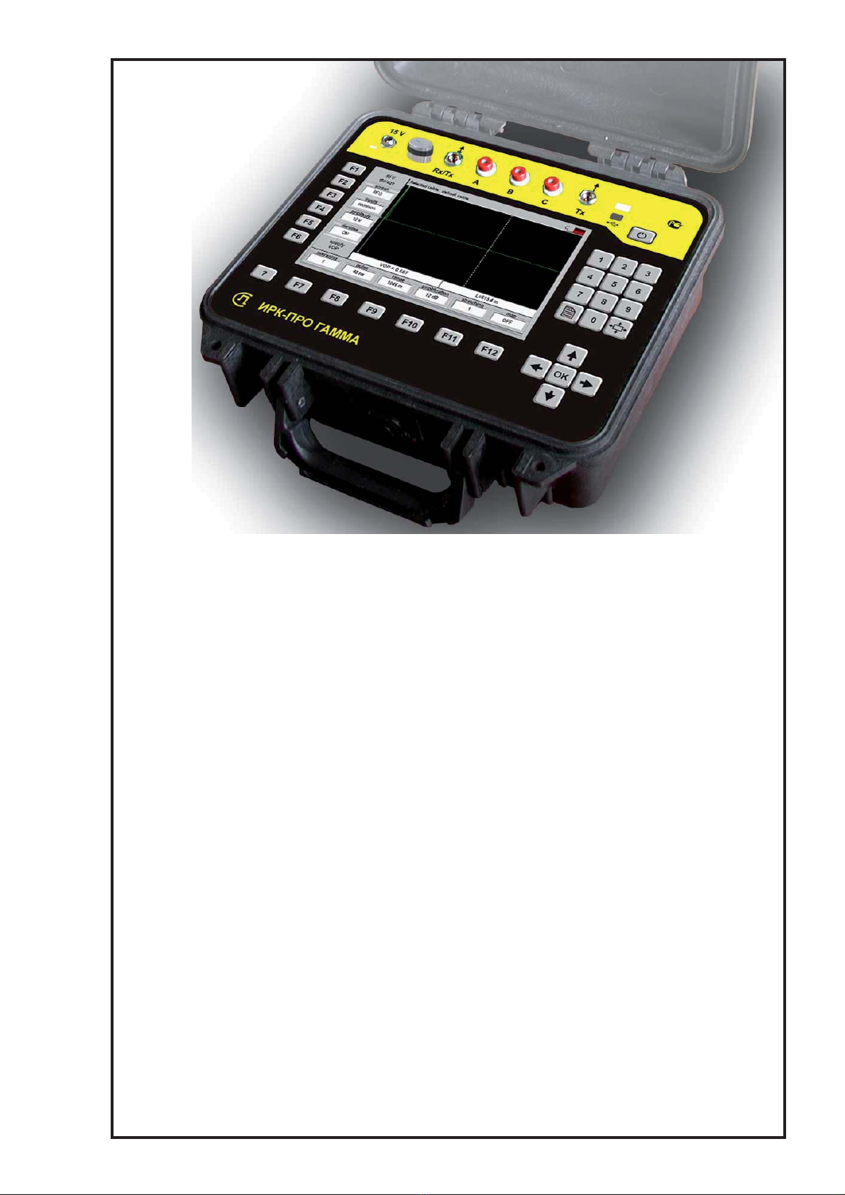
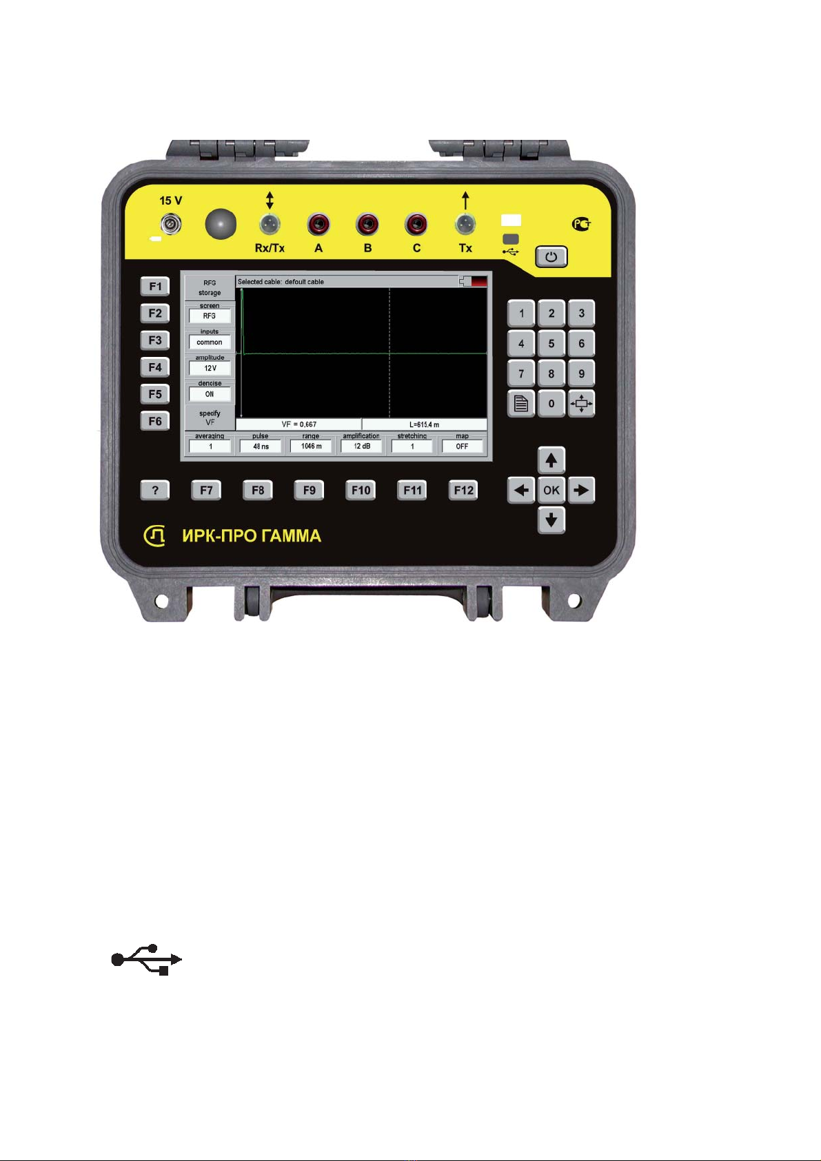
TURNING ON THE DSP TDR
Preliminary choose a cable in Main Menu. The device will adjust on the selected cable
gauges.
If you do not choose a cable – the device will adjust on default cable gauges.
Connect the device to a line through a socket [INPUT/OUTPUT] by the measuring cable.
Connect a red cable to a test line. Blue cable is standby cable for frequency measurements (it
does not use during the TDR operating).

11
TRACE VIEWING
Linear scale
There are two cursors on the TDR screen, between them the distance is measured on the trace.
To make a cursor an active – press the ◄► keys. To vertical move a trace – press the ▲▼
key.
To operate with the trace gauges use the following keys: [PULSE], [RANGE],
[AMPLIFICATION]. At setting the viewing range the device select itself the measuring pulse
width. The [STRETCHING] key is used to view the detail trace around an active cursor. The
[MAP] key is used to view the whole cable. The [AVERAGING] key is used to eliminate the
occasional noises and to rice picture stability during the averaging increasing.
The keys on the left vertical part of the menu are changing the TDR working mode: trace
recording [trace memory], activation of the logged trace for the comparison [+ memory]; work
in separate or combined mode; adjusted pulse amplitude, the mode of averaging for a line with
intensive noise.
The keys on the left vertical part of the menu:
Trace recording [trace memory];
activation of the logged trace for the comparison [+ memory];
work in separate or combined mode;
selection of the match resistance;
selection of the scale (linear, logarithmic, pseudologarithmic)

12
Logarithmic scale «Logarithm»
The screen in logarithmic scale:
This scale is used for the fast-access retrieval of the heterogeneity. The total viewing range is
100 dB. The top screen part is 0 dB, the bottom screen part –100 dB. The [AMPLIFICATION]
key do not have an influence on trace displaying. There is the signal level
UdB
in dB near the
cursor, relatively the measuring pulse level 0
U:
0
20 lg U
UdB U
=×
,
The echo – signal level Uis taken an absolute value, as far as the echo-signal can be positive
or negative. The positive values are displayed green and the negative values are yellow. On
rather long cables the negative values are seldom, and such image display feature is not falsify
a usual situation. Though, on the small pieces the picture may cause unusual. Switch on the
linear scale.
To make a logarithmic scale more usual there are realized an additional viewing mode –
« +/-log ».
Logarithmic scale «±Logarithm »
These logarithmic scale is taken into account a signal character (+ or -): the positive signal
levels are displayed in the top part of the screen, the negative signal levels are displayed in the
bottom part of the screen ( from the top part: 0 dB of the positive signal, 60 dB, -60 dB, 0 dB
of negative signal).
You can select the suitable viewing mode by pressing the keys. Logarithmic scales it is
recommended to use with a rather long cables (more than 2-3 km), with a short cables it is
recommended to use a linear mode.
Installation for a distance measurement
If you does not choose the cable and work with default cable - it is necessary to establish VF (or
CC) an a range of a cable viewing. The distance between cursors will be calculated according
to VF in selected view range.
If the VF is unknown, the device will establish it on a Cable Type. For this purpose select e
necessary mark in Main Men \ Cable selection \ Cable Type.

13
MEASUREMENT OF THE DISTANCE
Measurement of the distance must be made after setting of VF or selecting of a cable from the
List.
Measurement of distance is always carried out between two cursors. For measurement of
the distance from the cable beginning to heterogeneity it is necessary to make a zero cursor
become an active. Above the zero cursor there should be a label. If there is no label, press
[ОК] - and label will appear above the zero cursor. Establish the cursor on the beginning of
a measuring pulse by the ◄► keys. Then pressing the [ОК] key switch to the measuring
cursor and establish it on the beginning of the reflected pulse. Cursors should be established
on the pulse beginning, instead of on a maximum (top) of a pulse. For more exact positioning
of the cursors it is recommended to use the zoom.
LOCALIZATION OF PAIR MISBALANCING BY TDR
This method allows locating the place of symmetry failure of the cable pair. For this purpose
in the TDR measurements you should to use the measuring scheme of asymmetry attenuation
LBal. You can detect a balance failure and noise security failure. Disbalance of the cable pair
is lead to the loss of noise security. What fact can cause a symmetry breaking of the cable
pair? The protection elements and defective cross connections; defective splices and splitter;
insulation defects, split location Defective connections can cause an ohmic asymmetry of the
cable pair Ra . Insulation defects are accompany with the resistance decreasing with respect to
ground or neighbors wires LQ
R.
Measuring of the misbalancing cable pair location
For TDR with the symmetrical input and output.
The measuring pulse generator output is connected to the twisted pair with local defect. The
waves distributed along the symmetrical cable pair and have a small influence to cable shield
and to another cable pair. The influence is determined from
LBal
(Longitudinal balance).
For typical network the value of
LBal
does not exceed the level of -40 dB. On this value the
influence (caused by own heterogeneity of the cable) is decreased and allow to increase the
limit value of detected defect in two orders by comparison with the similar way.

14
Splice with ohmic asymmetry
For the splice with an active asymmetry component it is possible to create an equivalent
circuit:
There is possible a localization of a faulty contacts in the splice from 0,7 Ohm for the cable
of 3rd category (instead of 70 Ohm of usual hookup). For the cable of 4th category – from 0,1
Ohm.
Leakage
The insulation fault can cause the cable pair misbalancing, if there is damaged the one wire in
the cable pair (the leakage on the shield or on the wire of another pair).
The expected limit of leakage definition is increasing for the cable: of Category 3 from the
value 110 Ohm up to 11 kOhm, of Category 4 from 40kOhm up to 50 kOhm.
Example
We are use the IRK-PRO GAMMA device in the mode of DSP TDR with the following
hookup:

15
Leakage
During the amplification of 36 dB on the cable of 600m with the leakage on the distance of 300
m were obtained the following trace:
Obviously, the leakage of 13 kOhm is simply defined rather than open-cable. The open-cable
does not cause an asymmetry and its signal is successfully attenuated at the expense of cable
pair symmetry. In much the same way the measuring pulse is attenuated and causes a difficult
identification. To positioning of the first cursor on the measuring pulse – switch the device
in to combined mode. The reflection polarity is defined from TDR connecting and cable pair
asymmetry character (+ or -).
Splice with ohmic asymmetry
During the amplification of 39 dB on the cable of 600m were obtained the following trace:
Splice with asymmetry of 1 Ohm is clearly defined against the background of own cable
heterogeneity.

16
BRIDGE MEASUREMENTS
You can select bridge measurements in Main Menu.
MULTIFUNCTIONAL SCREEN
The multifunctional screen is divided on 4 sections:
1. the protocol section allows to protocol the measurements results.
2. to select the switching section mode (on the left part of the screen) - press the F1 – F6
keys.
3. the measurements section. The given measurements are displayed in the measurements
section according to whole 3 cable connecting АС, ВС and АВ. You can see the
measurement result of selected cable connection in the big window. To switch the cable
connections – press the ▲▼ keys.
4. the Menu (bottom line) is control the measurements – F7 – F12 keys.

17
INSULATION MODE
Measuring hookup:
Measuring section:
Menu:
K factor – to search the faults.
Threshold MOhm – setup for the bottom indicator - line (imitating the pointer
movement). It is convenient for the rapid check of cable pair good condition.
U test – test voltage: 400 V for defects searching, 180 V for work without turning off
the equipment.
Averaging – quantity of filters averaging: during the unstable indications it is
recommended to increase the averaging quantity. For rapid measurements you should
to decrease the averaging quantity.
Filter: auto – regular restart of the filter, manual – start by the [ОК] key. Before
turning on the manual filter it is necessary the cables complete charging. The filter
work is accompanied by bottom indicator movement.

18
CAPACITY MODE
Measuring hookup:
Measuring section:

19
LOOP MODE
Measuring hookup:
Measuring section:
The loop is measured between only А& Вwires. The measurement result is counted in the
cable length if you have selected a cable type.

20
OHMIC ASYMMETRY MEASUREMENT
Close a test wires at the far end between themselves and to cable shield (or to any back wires).
Connect the Аand Вwires to the test wires, and the Сwire connect to the shield.
Turn on the filter in the LOOP. After the creeping line working the device will remember a loop
resistance. In the LEAKAGE mode press the [asymmetry] key. The result will be recorded.
Measuring hookup:
Measuring section:
Table of contents