Mastech MS6813 User manual

MS6813
Multi Function Network Cable Tester
Users Manual
CO-AX
RJJJ
RJ45
Multi-Function Wire Tracer
SHIELD
7-8
4-53-61-2
TEST
BNC
Short Reversed Split Pairs
Miswire
OFF
CONT TONE
red fauit
green good
MS6813
TRANSMI TTER
10 Base T
Token Ring
258A
EIA&TIA568


01 02
To Avoid Possible Electric Shock Or
Personal Injury:
Out of Box
• Use the Tester only as specified in this manual
or the protection provided by the Tester might
be impaired.
• Do not place the Tester near explosive gas or vapor.
• Read the Users Manual before use and follow all
safety instructions.
Check the Tester and accessories thoroughly before
using the Tester. Contact your local distributor if the
Tester or any components are damaged or malfunction.
Limited Warranty And Limitation
Of Liability
This MS6813 product from Mastech will be free from
defects in material and workmanship for one year
from the date of purchase. This warranty does not
cover fuses, disposable batteries, or damage from
accident, neglect, misuse, alteration, contamination,
or abnormal conditions of operation or handling.
Resellers are not authorized to extend any other
warranty on Mastech's behalf. To obtain service during
the warranty period, contact your nearest Mastech
authorized service center to obtain return authorization
information, then send the product to that Service
Center with a description of the problem.
Accessories
• One Users Manual
• 1 9V 6F22 Battery
Safety Information
TO REDUCE THE RISK OF FIRE, ELECTRICAL
SHOCK, PRODUCT DAMAGE OR PERSONAL
INJURY, PLEASE FOLLOW THE SAFETY
INSTRUCTIONS DESCRIBED IN THE USER
MANUAL. READ THE USER MANUALS BEFORE
USING THE TESTER.
WARNING
DO NOT PLACE THE TESTER IN ANY
ENVIRONMENT OF HIGH PRESSURE, HIGH
TEMPERATURE, DUST, EXPLOSIVE GAS OR
VAPOR. TO ENSURE SAFE OPERATION AND
LIFE OF THE TESTER, FOLLOW THESE
INSTRUCTIONS.
WARNING
Safety Symbols
Important safety message
Conforms to relevant European Union directives


05 06
1.2 Components and Buttons
A. Transmitter (main)
B. Receiver
C. matching box (remote)
CO-AX
RJJJ
RJ45
Multi-Function Wire Tracer
SHIELD
7-8
4-53-61-2
TEST
BNC
Short Reversed Split Pairs
Miswire
OFF
CONT TONE
red fauit
green good
MS6813
TRANSMITT ER
10 Base T
Token Ring
258A
EIA&TIA568
20
19
18
22
21
13
3
4
7
10
11
12
1
2
5
9
6
13
14
15
16
17

08
2. Using the Tester
2.1 Network Cable Testing
TO AVOID ELECTRICAL SHOCK AND INJURY,
UNPOWER THE CIRCUIT WHILE PERFORMING
TESTS.
WARNING
2.1.1 Error Indicator
A wire pair indicator flashes (indicator #13,14,15,16)
indicates an error in the connection. Error indicator
flashes specify an error. If more than one wire pair
indicator flashes, troubleshoot on each case until all
the indicators go back to GREEN(Normal).
Fig.4 SPLIT PAIRS
Fig.3 REVERSED
Fig.2 MISWIRE
Fig.1 SHORT

9 10
The Tester only shows one type of error per test.
Fix one error first then make sure to perform the test
again to check other possible errors.
Open Circuit: Open Circuit is not commonly seen
and therefore no indication is included in the Tester.
Typically there are 2 to 4 coaxial cables pairs in the
network. Corresponding indicators are off if RJ45
sockets are not connected with coaxial cable pairs.
User debugs the network with the wire pair
indicators accordingly.
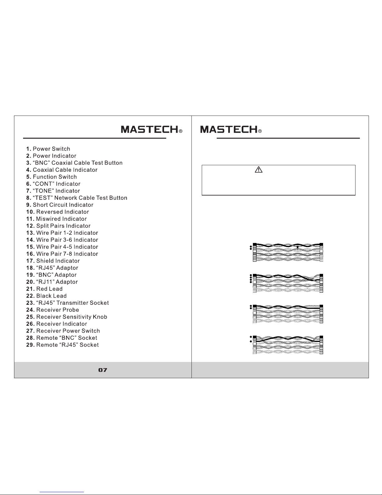
Short Circuit: shown in Fig.1.
Miswired: shown in Fig. 2: two pairs of wires are
connected to wrong terminals.
Reversed: shown in Fig.3: Two wires within the pair
are reversely connected to the pins in the remote.
Split Pairs: shown in Fig.4: Split pairs occurs when
the tip (positive conductor) and ring (negative
conductor) of two pairs are twisted and interchanged.
Note:
2.1.2 Test Mode
Follow the steps:
a) Connect one of the wires to RJ45 transmitter socket.
b) Connect the other end to RJ45 receiver socket.
c) Turn the Tester power on.
d) Press “TEST” button once to start testing.
e) During the test press “TEST” button again to stop
testing.
Example: wires pair 1-2 and pair 3-6 are short circuit.
In test mode, the error indicators will show as following:
• 1-2 and 3-6 indicators flash green lights, short circuit
indicator flash red light.
• 4-5 indicator shows green lights (no error)
• 7-8 indicator shows green lights (no error)
2.1.3 Debug Mode
In Debug Mode, detail of the connection error is
displayed. Condition of every pair of wires is shown
twice in order. With the wire pair indicators and error
indicators, the network cable can be indentified and
debugged. Follow the steps:
a) Connect one end of wire to RJ45 transmitter socket.
b) Connect the other end of wire to receiver socket.
c) Power on the Tester, power indicator is on.
d) Press and hold “TEST” button until all the wire pairs
and error indicators are all on, release the button
afterward.
e) Determine the error from the indicators.
f) If a wire pair indicator turns green twice (one short,
one long), and other error indicators are off, then
the wire pair is in good condition.
g) If the wire pair malfunctions, the corresponding
indicator will flash once and then turn on (long)
again with the error indicator on.
h) In debugging mode, press and release the “TEST”
button to end the debug.


13 14
2.4.1 Sending Audio Frequency Signal:
Connect both leads(“RJ45” Adaptor、“BNC”Adaptor、
“RJ11” Adaptor、the red lead and back lead) on the
transmitter to the network cable (or connect the red lead
to target cable and black lead to ground depends on the
circuit). Turn the transmitter switch to “TONE” mode and
the indicator will lights up. Press and hold receiver power
button, move the receiver close to the target network to
receive signal. Adjust receiver volume through sensitivity
switch.
Use “TONE” mode on transmitter along with the
receiver to track cable. Connect the wire adaptor to
the target network (or connect the red lead to target
cable and black lead to ground depends on the circuit).
Switch to “TONE” mode on the transmitter, “TONE”
indicator turns on. Press and hold the power button
on the receiver. Move the receiver near the target
network to receive audio frequency signal. The tester
detects the direction and continuity of the network cable.
Adjust receiver volume through sensitivity switch.
2.4.2 Tracking Network Cable
2.5 Telephone Line Modes Testing
Turn the switch on the transmitter to “OFF” mode.
When the target telephone line is at work, connect the
red lead to RING line and the black lead to TIP line, If,
a) “CONT” indicator turns green, the telephone line
is idle.
b) “CONT” indicator stays off, the telephone line is
off-hook.
c) “CONT” indicator turns green along with periodic
red flash, the telephone line is in vibrate mode.
d) When connect receiver antenna to an explored
telephone wire, press and hold the receiver power
button to receive the audio signal.
2.5.1 Differentiate TIP or RING wire:
Turn the switch on the transmitter to “OFF”, connect
the corresponding wire adaptor to the open telephone
lines in the network. If,
a) “CONT” indicator turns green, the red lead on the
transmitter connects to RING of the telephone line.
b) “CONT” indicator turns red, the red lead on the
transmitter connects to TIP of the telephone line.
2.5.2 Determine Idle, Vibrate or in use (off-hook):
2.4 Network Cable Tracking
TO AVOID ELECTRICAL SHOCK AND INJURY, DO
NOT CONNECT RECEIVER TO ANY AC SIGNAL
LARGER THEN 24V.
WARNING

Other manuals for MS6813
1
Table of contents
Other Mastech Cable Tester manuals
Popular Cable Tester manuals by other brands

Prokit's Industries
Prokit's Industries Pro'sKit MT-7059 user manual

Cirris
Cirris signature 1100R+ Operator's/performance manual

Platinum Tools
Platinum Tools VDV MapMaster 3.0 T130 user manual

Extron electronics
Extron electronics Cable Cubby 600 user manual

Greenlee
Greenlee 38583 user guide

Steren
Steren HER-435 manual