AEMC CA7024 TDR User manual

CA7024
FAULT MAPPER
CABLE LENGTH METER
AND FAULT LOCATOR
ENGLISH User Manual
www. .com information@itm.com1.800.561.8187

Statement of Compliance
Chauvin Arnoux®, Inc. d.b.a. AEMC®Instruments
certifies that this instrument has been calibrated
using standards and instruments traceable to
international standards.
We guarantee that at the time of shipping your
instrument has met its published specifications.
The recommended calibration interval for this
instrument is 12 months and begins on the date of
receipt by the customer.
Serial #: ________________________________
Catalog #: 2127.80
Model #: CA7024
Please fill in the appropriate date as indicated:
Date Received: _________________________________
Date Calibration Due: _______________________
Chauvin Arnoux®, Inc.
d.b.a AEMC®Instruments
www. .com information@itm.com1.800.561.8187

Fault Mapper Model CA7024
1
Table of Contents
1. INTRODUCTION............................................................................... 3
1.1 International Electrical Symbols................................................3
1.2 Receiving Your Shipment..........................................................4
1.3 Ordering Information.................................................................4
1.3.1 Accessories and Replacement Parts............................4
2. PRODUCT FEATURES ...................................................................... 5
2.1 Description................................................................................5
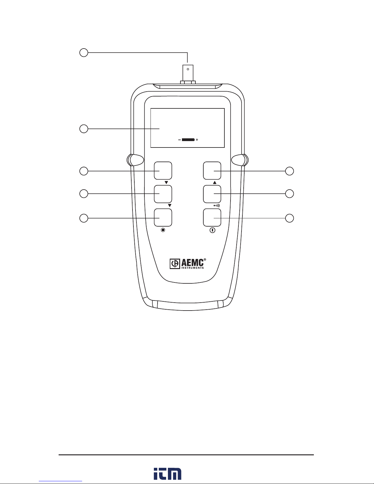
2.2 Fault Mapper Features .............................................................6
3. SPECIFICATIONS............................................................................. 7
4. OPERATION .................................................................................... 8
4.1 Principles of Operation .............................................................8
4.2 Accuracy and Velocity of Propagation (Vp) ..............................8
4.3 Getting Started..........................................................................9
4.4 Set-up Mode .............................................................................9
4.5 Programming a Custom Library Location ...............................10
4.6 Backlight .................................................................................11
4.7 Tone Generator.......................................................................11
4.8 Voltage Safety Warning (Live Sample) ...................................12
4.9 Determining and Measuring Vp Values ..................................13
4.10 Selecting a Library Cable or Setting Vp..................................14
4.10.1 Cable Library ..............................................................14
4.11 Attaching a Cable to the Fault Mapper ...................................16
4.12 Measuring Cable Length or Fault Distance ............................17
5. MAINTENANCE ............................................................................. 18
5.1 Changing the Battery ..............................................................18
5.2 Cleaning..................................................................................18
5.3 Storage ...................................................................................18
www. .com information@itm.com1.800.561.8187

2
Fault Mapper Model CA7024
Limited Warranty ...................................................................................20
Warranty Repairs...................................................................................20
www. .com information@itm.com1.800.561.8187

Fault Mapper Model CA7024
3
CHAPTER 1
INTRODUCTION
WARNING
● This instrument meets the safety requirements of IEC61010-
1:1995.
● TheModelCA7024isdesignedforuseonde-energizedcircuits
only.
● Connection to line voltages will damage the instrument and
couldbehazardoustotheoperator.
● This instrument is protected against connection to telecom
networkvoltagesaccordingtoEN61326-1.
● Safetyistheresponsibilityoftheoperator.
1.1 International Electrical Symbols
Thissymbolsigniesthattheinstrumentisprotectedbydoubleor
reinforced insulation.
This symbol on the instrument indicates a WARNING and that
the operator must refer to the user manual for instructions before
operating the instrument. In this manual, the symbol preceding
instructions indicates that if the instructions are not followed,
bodily injury, installation/sample and product damage may result.
Riskofelectricshock.Thevoltageatthepartsmarkedwiththis
symbol may be dangerous.
www. .com information@itm.com1.800.561.8187

4
Fault Mapper Model CA7024
1.2 Receiving Your Shipment
Upon receiving your shipment, make sure that the contents are consis-
tentwiththepackinglist.Notifyyourdistributorofanymissingitems.If
theequipmentappearstobedamaged,leaclaimimmediatelywiththe
carrier and notify your distributor at once, giving a detailed description of
any damage. Save the damaged packing container to substantiate your
claim.
1.3 Ordering Information
Fault Mapper Model CA7024.............................................Cat. #2127.80
Includes meter, carrying case, BNC pigtail with alligator clips, 4 x 1.5V AA batteries, user
manual and product warranty card.
1.3.1 Accessories and Replacement Parts
Tone Receiver / Cable Tracer Model TR03 ......................... Cat. #2127.76
www. .com information@itm.com1.800.561.8187

Fault Mapper Model CA7024
5
CHAPTER 2
PRODUCT FEATURES
2.1 Description
TheFaultMapperisahandheld,Alpha-Numeric,TDR(TimeDomainReec-
tometer)CableLengthMeterandFaultLocator,whichisdesignedtomeasure
thelengthofpowerandcommunicationcablesortoindicatethedistancetoa
fault on the cable, given access to only one end.
By incorporating Fast-edge Step TDR Technology, the Fault Mapper measures
cable length and indicates the distance to open or short circuit faults, to a range
of6000ft(2000m)onatleasttwoconductors.
The Fault Mapper indicates the cable length or fault distance and description
alpha-numerically on a 128x64 Graphical LCD.
An internal library of standard cable types enables accurate measurement
withoutthenecessityofenteringVelocityofPropagation(Vp)information,and
the Fault Mapper automatically compensates for different cable impedances.
TheFaultMapperincorporatesanoscillatingtonegenerator,whichisdetect-
ablewithastandardcabletonetracer,foruseinthetracingandidentication
of cable pairs.
Theunitalsodisplaysa“VoltageDetected”warningandsoundsanalarmwhen
connectedtoacableenergizedbymorethan10V,whichprohibitstesting.
Features:
Hand-held cable length meter and fault locator
Measures cable length and indicates distance to open or short circuit
faults to a range of 6000 ft (2000m)
Indicates cable length, fault distance and description,
alpha-numerically
Emits an audible tone used to trace a cable and identify the type of
fault
Displays “Voltage Detected” and warning sound when >10V is
present on the tested sample
www. .com information@itm.com1.800.561.8187

6
Fault Mapper Model CA7024
2.2 Fault Mapper Features
1
2
3
4
5
6
7
8
Alpha-Numeric TDR
FAULT MAPPER
®
MODEL CA7024
TEST /
Vp Vp
TDR /
AEMC Instruments
Fault Mapper V3.1B
Appletalk
Vp=66%
1. BNC input connector
2. Alpha-Numeric LCD
3. Vp (Velocity of Propagation) decrement button
4. Test/function select button
5. Backlight button
6. Vp (Velocity of Propagation) increment button
7. Mode select button (TDR or Tone Tracer)
8. PowerON/OFFbutton
www. .com information@itm.com1.800.561.8187

Fault Mapper Model CA7024
7
CHAPTER 3
SPECIFICATIONS
Range @ Vp=70%: 6000 ft (2000m)
Resolution (m): 0.1 m up to 100 m, then 1 m
Resolution (ft): 0.1 ft up to 100 ft, then 1 ft
Accuracy*: ±2% of Reading
Minimum Cable Length: 12 ft (4m)
Cable Library: Built-in
Vp (Velocity of Propagation): Adjustable from 0 to 99%
Output Pulse: 5V peak-to-peak into open circuit
Output Impedance: Automatic compensation
Output Pulse: Nanosecond rise Step Function
Display Resolution: 128 x 64 pixel graphical LCD
Display Backlight: Electroluminescent
Tone Generator: Oscillatingtone810Hz-1110Hz
Voltage Warning: Triggers@>10V(AC/DC)
Power Source: 4 x 1.5V AA alkaline batteries
Auto-off: After 3 minutes
Storage Temperature: -4 to 158°F (-20 to 70°C)
5 to 95% RH non-condensing
Operating Temperature: 32 to 112°F (0 to 40°C)
5 to 95% RH non-condensing
Altitude: 6000 ft (2000m) max
Dimensions: 6.5 x 3.5 x 1.5” (165 x 90 x 37mm)
Weight: 12oz(350g)
Safety: IEC61010-1
EN 60950
Index of Protection: IP54
EMC: EN 61326-1
CE: CompliancewithcurrentEUdirectives
*Measurement accuracy of ±2% assumes the instrument setting for velocity of propagation
(Vp) of the cable under test to be accurately set, and homogeneity of the velocity of propaga-
tion (Vp) along the cable length.
Specications are subject to change without notice.
www. .com information@itm.com1.800.561.8187

8
Fault Mapper Model CA7024
CHAPTER 4
OPERATION
4.1 Principles of Operation
TheFaultMapperworksbymeasuringthetimetakenforasignaltotravel
to the far end of the cable under test, or to an intermediate fault and return.
Thevelocityatwhichthesignaltravels,orVelocityofPropagation(Vp),
willdependonthecharacteristicsofthecable.
Based on the selected Vp and the measured travel time of the test pulse,
the Fault Mapper calculates and displays distance.
4.2 Accuracy and Velocity of Propagation (Vp)
The Fault Mapper measures distances to faults and cable lengths to an
accuracy of ±2%.
This measurement accuracy is based upon the correct value of Vp being
used for the cable under test, and homogeneity of the Vp along the cable
length.
If the Vp is set incorrectly by the operator, or the Vp varies along the length
ofthecable,thenadditionalerrorswillbeincurredandthemeasurement
accuracywillbeaffected.
See § 4.9 for setting the Vp.
NOTE:TheVpislesswelldenedwithunshieldedmulti-conductor
cable,includingpowercable,andislowerwhenacableistightly
woundonadrumthanwhenitisinstalledinalinearfashion.
www. .com information@itm.com1.800.561.8187

Fault Mapper Model CA7024
9
4.3 Getting Started
Theinstrumentisswitchedonandoffusingthegreenpowerbutton ,
foundonthelowerrightsideofthefrontpanel.
Whentheunitisrstswitchedonitwilldisplaytheopeningscreengiving
thesoftwareversion,thecurrentlyselectedcabletype/VelocityofPropa-
gation, and remaining battery capacity.
AEMC Instruments
Fault Mapper V3.1B
Romex 14/2
Vp=66%
4.4 Set-up Mode
Hold the
TDR /
button, then press the
TEST /
button to enter Set-up mode.
Feet
Eng (USA)
Edit Library
Contrast
>
• MeasurementunitscanbesettoFeetorMeters
• Languagescanbesetto:English,Français,Deutsch,Españolor
Italiano
• Auserprogrammablelibraryisavailabletostoreupto15custom-
izedsettings
• Thedisplaycontrastcanadjusted
Press the
TEST /
button to move the line selector (>)downthescreen.
Press the
Vp
or
Vp
button to change the setting of the line selected.
Press the
TDR /
button again to save changes and exit set-up mode.
NOTE: WhentheFaultMapperisturnedoff,itwillrememberthe
current set-up parameters. This feature is useful in the situation
wheretheoperatorisperformingmanytestsonthesametypeof
cable.
www. .com information@itm.com1.800.561.8187

10
Fault Mapper Model CA7024
4.5 Programming a Custom Library Location
To program a custom library location, enter the Set-up mode (see § 4.4).
Press the
TEST /
buttontoselectEditLibrary;thelineselector(>)should
be at Edit Library.
Press the
Vp
or
Vp
button
to enter the library programming mode.
• TheModelCA7024willdisplaytherstprogrammablecableloca-
tion in the library.
• ThefactorysettingforeachlocationisCustom Cable XwithaVp
= 50%,whereXislocation1through15.
Press the
Vp
or
Vp
button
to choose a cable location to program.
--- Choose Cable ---
Custom Cable 1
Vp = 50%
Next, press the
TEST /
button enter the Choose Character mode.
--- Choose Character ---
Custom Cable 1
Vp = 50%
• Thearrowcursorwillpointtotherstcharacter.
• Fifteencharactersareavailableforcablenaming.
Press the
Vp
or
Vp
button
to move the selection cursor to the left or right
respectively. Once the desired character is selected, press the
TEST /
button to enter the Edit Character mode.
Next, press the
Vp
or
Vp
button
to change the character at the selec-
tion point.
www. .com information@itm.com1.800.561.8187

Fault Mapper Model CA7024
11
The available characters for each character location are:
Blank!“#$%&’()*+,-./0123456789:;<=>?@A
BCDEFGHIGJLMNOPQRSTUVWXYZ[\]^_a
bcdefghIjklmnopqrstuvwxyz
When the desired character is selected, press the
TEST /
button to move
to the next character to edit.
After the last character is selected, press the
TEST /
button again to
move the cursor to the VP adjustment. Next, press the
Vp
or
Vp
button
to increase or decrease the Vp, as necessary, for the cable type.
When the Vp selection is complete, press the
TDR /
button to return to
the Choose Character mode and a second time to return to the Choose
Cable mode.Youmaynowdeneanothercableforthelibraryorpressthe
TDR /
button a third time to return to the main set up screen. Pressing
the
TDR /
buttonagain,atthispoint,willexittheSet-up mode.
4.6 Backlight
Thedisplaybacklightisswitchedonandoffwiththe button.
4.7 Tone Generator
The Fault Mapper may also be used as a tone generator, to trace and
identifycablesandwires.Theuserwillneedacabletonetracer,suchas
the AEMC Tone Receiver/Cable Tracer Model TR03 (Cat. #2127.76) or
equivalent.
www. .com information@itm.com1.800.561.8187

12
Fault Mapper Model CA7024
Pressing the
TDR /
buttonwillinjectawarbling(oscillating)toneintothe
cableorlinkundertest.Whenset,thefollowingwillbedisplayed:
* * * * * * * * * * * * * * * * * * *
* * * * * * * * * * * * * * * * * * *
Warble Tone
Theinjectedsignaloscillatesbetween810Hzand1110Hz,sixtimesper
second.
NOTE: The auto-off function is disabled in Tone Generator mode,
so that the tone can be injected into a cable for an extended period
oftimewhiletracingtakesplace.
See §4.11 for attaching a cable to the Fault Mapper
4.8 Voltage Safety Warning (Live Sample)
TheFaultMapperisdesignedtoworkonnon-energizedcablesonly.
WARNING: If the Fault Mapper is accidentally connected to a cable
carryingavoltagegreaterthan10V,awarningtonewillbeemitted,
testingwillbeprohibited,andthewarningdisplayshownbelowwill
appear.
In this situation the operator should immediately disconnect the Fault
Mapper from the cable.
* * * * * * * * * * * * * * * * * * *
* * * * * * * * * * * * * * * * * * *
! ! ! !
Voltage Detected
! ! ! !
www. .com information@itm.com1.800.561.8187

Fault Mapper Model CA7024
13
4.9 Determining and Measuring Vp Values
Velocity of Propagation (Vp) values are characteristic of each cable type
and brand.
The Vp is used to measure the length of a cable and to measure a fault
location. The more accurate the Vp, the more accurate the measurement
resultwillbe.
ThecablemanufacturermaylisttheVpontheirspecicationsheetormay
beabletoprovideitwhenasked.Sometimesthisvalueisnotreadilyavail-
able,ortheusermaywishtodetermineitspecicallytocompensatefor
cable batch variations or for special cable applications.
Thisisquiteeasy:
1. Take a cable sample of exact length increments (ft or m) longer than
60ft (20m).
2. Measure the exact length of the cable using a tape measure.
3. Connect one end of the cable to the Fault Mapper (see § 4.11). Leave
theendunterminatedandmakesurethewiresdonotshorttoeach
other.
4.
Measure the length and adjust the Vp until the exact length is displayed.
5. When the exact length is displayed, Vp is established.
www. .com information@itm.com1.800.561.8187

14
Fault Mapper Model CA7024
4.10 Selecting a Library Cable or Setting Vp
Press the
Vp
and
Vp
buttonstomoveupanddownthroughthelibrary.
4.10.1 Cable Library
Cable Type Vp (%) Z (Ω)
A.I.W 10/4 47 50
A.I.W 16/3 53 50
Alarm Belden 62 75
Alarm M/Core 59 75
AlumaexXHHW-2 57 50
Belden 8102 78 75
Belden 9116 85 75
Belden 9933 78 75
CAT5 STP 72 100
CAT5 UTP 70 100
Cirtex 12/2 65 50
Coax Air 98 100
Coax Air Space 94 100
Coax Foam PE 82 75
Coax Solid PE 67 75
Coloniel 14/2 69 50
CW1308 61 100
Encore 10/3 65 50
Encore 12/3 67 50
Encore HHW-2 50 50
Ethernet 9880 83 50
Ethernet 9901 71 50
Ethernet 9903 58 50
Ethernet 9907 78 50
General 22/2 67 50
IBM Type 3 60 100
IBM Type 9 80 100
Main SWA 58 25
Multicore PVC 58 50
RG6/U 78 75
RG58 (8219) 78 50
RG58 C/U 67 50
RG59 B/U 67 75
RG62 A/U 89 100
Romex 14/2 66 25
StabiloyXHHW-2 61 100
Telco Cable 66 100
T&E BS6004 54 50
Twinax 66 100
URM70 69 75
URM76 67 50
www. .com information@itm.com1.800.561.8187

Fault Mapper Model CA7024
15
If the cable to be tested is not listed in the library, or a different Vp is
required,continuepressingthe
Vp
button, past the top of the library.
Vpwillbedisplayedwithavalue,whichcanbeselectedfrom1to99%.If
theVpvalueisnotknown,see§4.9.
AEMC Instruments
Fault Mapper V3.1B
Vp=95%
NOTE:WhentheFaultMapperisturnedoff,itwillrememberthe
last selected Cable Library or Vp setting. This feature is useful in the
situationwheretheoperatorisperformingmanytestsonthesame
type of cable.
www. .com information@itm.com1.800.561.8187

16
Fault Mapper Model CA7024
4.11 Attaching a Cable to the Fault Mapper
1. Makesurethatthereisnopowersupplyorequipmentattachedtothe
cable to be tested.
2. Checkthatthefarendofthecableiseitheropenorshorted(nottted
witharesistivetermination).
3. Attach the Fault Mapper to one end of the cable to be tested.
The cable attachment is via a BNC connector located at the top of the unit.
For unterminated cables use the alligator clip attachment provided.
Coaxial Cable: Connect the Black clip to the center wire and the Red
clip to the shield/screen.
Shielded Cable: Connect the Black clip to a wire adjacent to the
shield and the Red clip to the shield.
Twisted Pair: Separate out one pair and connect the red and black
clipstothetwowiresofthepair.
Multi-conductor Cable:Connecttheclipstoanytwowires.
Coaxial Cable
Shielded Cable
Twisted Pair
Multi-conductor Cable
www. .com information@itm.com1.800.561.8187

Fault Mapper Model CA7024
17
4.12 Measuring Cable Length or Fault Distance
• Selectthecabletypefromthelibrary(see§4.10)orselectthecableVp
(see § 4.9) and attach to the cable to be tested as previously described
in § 4.11.
• Pressthe
TEST /
button.
Assuming there are no opens or shorts in the cable, the length of the cable
willbedisplayed.
Forlengthslessthan100ft,the displayed value will betoonedecimal
place.
AEMC Instruments
Fault Mapper V3.1B
Open Circuit
63.2ft
For lengths over 100ft the decimal place is suppressed.
AEMC Instruments
Fault Mapper V3.1B
Open Circuit
632ft
If there is a short at the end of the cable or at some point along the cable,
thenthedisplaywillshowthedistancetotheshort.
AEMC Instruments
Fault Mapper V3.1B
Short Circuit
87.2ft
www. .com information@itm.com1.800.561.8187

18
Fault Mapper Model CA7024
CHAPTER 5
MAINTENANCE
Use only factory specied replacement parts. AEMC® will not be held
responsible for any accident, incident, or malfunction following a repair
done other than by its service center or by an approved repair center.
5.1 Changing the Battery
Disconnecttheinstrumentfromanycableornetworklink.
1. Turn the instrument OFF.
2. Loosenthe2screwsandremovethebatterycompartmentcover.
3. Replacethebatterieswith4x1.5VAAalkalinebatteries,observing
the polarities.
4. Reattach the battery compartment cover.
5.2 Cleaning
Disconnect the instrument from any source of electricity.
• Useasoftclothlightlydampenedwithsoapywater.
• Rinsewithadampclothandthendrywithadrycloth.
• Donotsplashwaterdirectlyontheinstrument.
• Donotusealcohol,solventsorhydrocarbons.
5.3 Storage
If the instrument is not used for a period of more than 60 days, it is recom-
mended to remove the batteries and store them separately.
www. .com information@itm.com1.800.561.8187
Table of contents
Other AEMC Cable Tester manuals