Sweiss SKYVIEW 610 User manual

SKYVIEW 610 – INSTRUCTIONS MANUAL
MANUAL DE INSTRUCCIONES
INSTRUCTION MANUAL
SKYVIEW 610
IMPORTANT: Read this Owner’s Manual Completely before attempting to use this equipment.
Save this manual and keep it handy for quick reference. Pay particular attention to the safety
instructions we have provided for your protection. Contact your distributor if you do not fully
understand this manual.

CARETA DE SOLDADURA FOTOSENSIBLE
IMPORTANTE: Lea el manual de usuario completamente antes de utilizar el equipo. Mantenga
este manual al alcance para futuras referencias. Ponga especial atencion a las intrucciones de
seguridad para la proteccion de su integridad sica. Contacte a su distribuidor local si tiene
alguna duda acerca de la operación de cualquiera de los equipos SWEISS .
IMPORTANT: Read this Owner’s Manual Completely before attempting to use this equipment.
Save this manual and keep it handy for quick reference. Pay particular attention to the safety
instructions we have provided for your protection. Contact your distributor if you do not fully
understand this manual.
SKYVIEW 610

CONTENIDO
1.BEFORE WELDING ................................................................................................................1
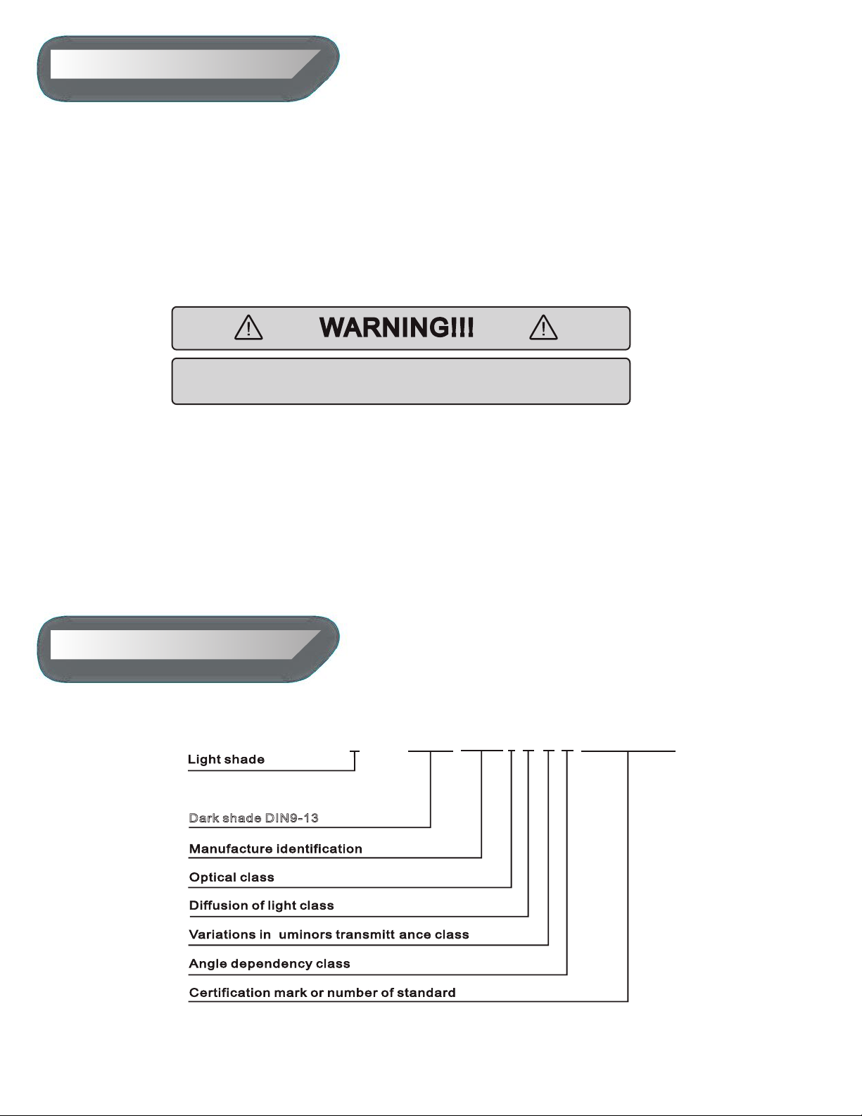
2.MARKINGS................................................................................................................................1
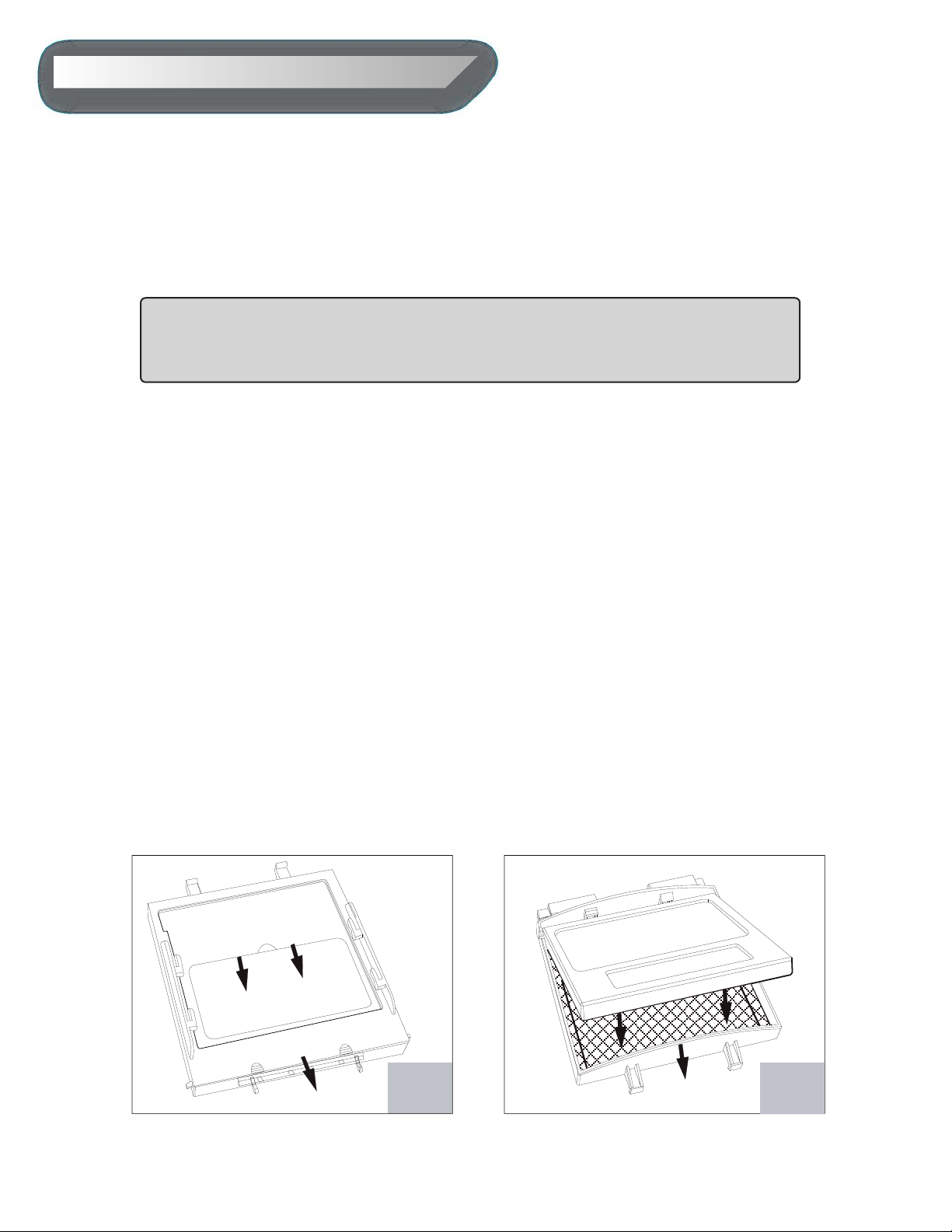
3.STORAGE AND MAINTENANCE........................................................................................2
4. ADJUSTING HEADGEAR (FOUR PARTS).......................................................................3
5. AUTO-DARKENING FILTER FUNCTIONS.......................................................................4
5.1 Selecting the Operating Mode....................................................4
5.2 Selecting Delay Time........................................................................4
MA X 1.0 second-Longer.....................................................................4
MIN (0.1 s ec ond)-Shorter delay......................................................4
5.3 Selecting Sensitivity...........................................................................5
5.4 Power........................................................................................................5
6. TECHNICAL SPECIFICATION.................................................................................5
7. COMMON PROBLEMS AND REMEDIES............................................................6
8. SHADE SELECTION CHART..................................................................................6
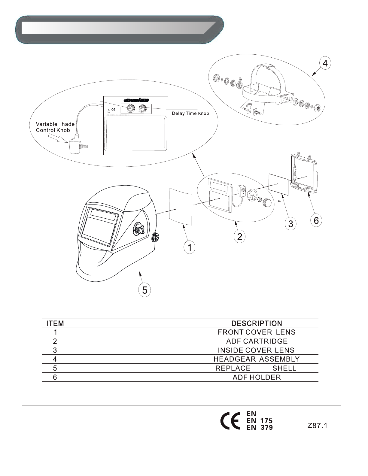
9. PARTS LIST...................................................................................................................7
1.ANTES DE SOLDAR ................................................................................................................8
2.ESPECIFICACIONES..................................................................................................................9
3.ALMACENAMIENTO Y MANTENIMIENTO........................................................................9
4.AJUSTES DEL ARNES DE CABEZA........................................................................................11
5.FUNCIONES DEL FILTRO ELECTRONICO...........................................................................12
5.1 Selección del tipo de función..........................................................12
5.2 Selección del tiempo de retraso....................................................12
“MAX” (1.0 segundos)..........................................................................12
“MIN” (0.1 segundos)...........................................................................12
5.3 Selección de sensibilidad:................................................................13
5.4 Alimentación........................................................................................13
6. ESPECIFICACIONES TECNICAS............................................................................14
7. PROBLEMAS Y SOLUCIONES................................................................................14
8. TABLA DE SELECCIÓN DE SOMBRAS................................................................15
9. LISTA DE PARTES......................................................................................................16
ENGLISH
ESPAÑOL

1. BEFORE WELDING
2. MARKINGS
Auto-Darkening welding helmet is designed to protect the welders eyes from
harmful radiation including visible light, ultraviolet radiation (UV) and in f r a - r e d r
a d i a t i o n ( IR) r e s u l t ing f rom cer tain arc and gas we ld in g cesses when used
in accordance with these User Instructions.
This welding helmet is suitable for all types of electro-weldings:covered electrodes,
MIG/MAG,TIG/WIG, plasma welding,cutting and laser welding (only selected models
with two shade ranges i.e.5-8 and 9-13), except for gas welding.
Never place the helmet or the lter on hot surface.
- Use only within the temperature range of -10°C to+60°C.
- Do not immerse the lter (auto-dakening lter) in water.
- Do not expose the lter to liquids and protect it from dirt.
- Regularly replace the cracked-scratched protection cover lens. If this helmet
doesn’t darken upon striking an arc, stop welding immediately and contact your
supervisor or your dealer.
The lter is marked wi th the shade range and optical classication. The following is
an example(EN379) :
Make suret o remove any additiona l protection
foil from both sides of Protection Lens .
4 9-13 SWG1 1 1 2/EN379 CE/ / / / /
Dark shade DIN9-13
l
1

3.STORAGE AND MAINTENANCE
When not in use,the lter should be stored in a dry place within the temperature
range of -20°C to +70°C Prolonged exposure at temperature above 45°C ma y
decrease the battery lifetime of the lter.It is recommended to keep the solar cel l s
of the f i lter in the dark or not exposed to light during storage in order to maintain
power down mode.This can be achieved by simply placing the lter face down on
the storage shelf.
It is always necessary to keep the solar cells and the light sensors of the lter free of
dust and spatters:cleaning can be done with a soft tissue or a cloth soaked in mild
detergent (or alcohol).Never use aggressive solvents such as acetone.
If protection screens are in any way damaged,they must be immediately replaced.
- Replacing External Cover Lens : Remove lter holder by moving locks toward
center (Fig.1) and lift up the lter holder to remove/replace the external cover lens.
Replacing Internal Cover Lens : Place your ngernail in recess below the cartridge of
view window and ex lens upwards until it releases from edges of the cartridge of
view window.
- Change the Shade Cartridge: Remove lter holder assembly from helmet shell (See
Fig.1). Then ex top end of the lter holder to allow lter cartridge to be removed
from the frame. Install new lter cartridge into frame(See Fig.2). Make sure that the
lter cartridge is inserted in lter holder correctly as shown and install lter holder
assembly into helmet shell.
Protection cover Lens ,both internal and external (Polycarbonate)
must be used in conjunction with the autodarkening lter in order
to protect it against permanent damage.
Fig.1 Fig.2
2

4. ADJUSTING HEADGEAR (FOUR PARTS)
4.1 Headgear top (see adjustment“W” in the g. 4)
4.2 Headgear tightness (see adjustment“Y” in the g. 4)
4.3 Headgear tightness (see adjustment“Y” in the g. 4)
Adjusting headgear for proper depth on the head to ensure correct balance and
stability.
Pressing the adjusting knob located on the back of the headgear and turn left or
right to a desired tightness.
Adjusting the distance between the face and the lens by loosening both outside
tension knobs and press inward to free from adjustment slots. Move forward or back
to desired position and retighten. (Both sides must be equally positioned for proper
vision.)
4.4 Angle adjustment (see adjustment “X”in the g. 4)
Four pins on the right side of the headgear top provide adjustment for the forward
tilt of the helmet. To adjust, loosen the right outside tension adjustment knob then
lift on the control arm tab and move it to the desired position and retighten tension
adjustment knob.
W
′ ′
′ ′
Y
′ ′
Z
′ ′
T
′ ′
Z
Y
Fig.4
X
3

5. AUTO-DARKENING FILTER FUNCTIONS
5.1 Selecting the Operating Mode
5.2 Selecting Delay Time
For some lters, two modes of operation can be selected: welding or grinding. (See
Fig.3)
Grind Mode: shade function is turned o. In this mode the shade is xed in the light
state that allowing a clear view to grind a weld with the helmet providing face
protection. Used for metal grinding applications.
Weld Mode-Used for most welding applications.In this mode the shade function is
turned on. When it optically senses a welding arc, please select a suitable shade
level,delay time and sensitivity as required.
The Delay Time knob will vary from dark to light time,it can be set at MAX (1.0
second) or MIN (0.1second) by using the innitely dial knob.(See Fig.6)
MA X 1.0 second-Longer delay is for most welding applications, specially for high
amperage (current) applications.
MIN (0.1 s ec ond)-Shorter delay is for Spot welding applications
Grind mode is intended for Grinding not for welding. Before restarting
welding, the knob should be set back to the“ Weld position”
Fig.6
LO
HI
Fig.7
Longer delay can also be used for T IG Welding in order to prevent the lter
opening when the light path to the sensors is temporarily obstructed by a hand,
torch, etc.
4

6. TECHNICAL SPECIFICATION
5.3 Selecting Sensitivity
5.4 Power
The sensitivity can be set at ”HI”(High) or ”LO”(Low) by using the innitely dial knob.
(See Fig.7)
As a simple rule for optimum performance, it is recommended to set sensitivity
at the High at the beginning and then gradually reduce it, until the lter reacts only
to the welding light ashes and without annoying spurious triggering due to
ambient
light conditions (direct sun, intensive articial light, neighboring welder ’s arcs etc.).
“HI” (High)- Most for welding applications but specially for low welding current
work.
“LO” (L ow)- Only in some specic surrounding lighting conditions in order to avoid
unwanted triggering.
All the welding helmets are powered by solar energy. Some of models are without
replaceable batteries. Some selected models need to replace Li-Batteries when LOW
BATTERY Light starts blinking.
Car e 114*133*10mm
(4.48*5.24*0.39in)
110*90*9mm
(4.33*3.54*0.35in)
110*90*9mm
(4.33*3.54*0.35in)
110*90*9mm
(4.33*3.54*0.35in)
110*90*8mm
(4.33*3.54*0.31in)
98*88mm
(3.86*3.46in)
100*53mm
(3.93*2.09in)
100*53mm
(3.93*2.09in)
100*53mm
(3.93*2.09in)
96*40mm
(3.93*1.62in)
tion 1/1/1/2 1/1/1/2 1/1/1/2 1/1/1/2 1/1/1/2
4 Independent 4 Independent 4 Independent 2 Independent 2 Independent
Shade Variable DIN4/5-8/9-13
(Internal Variable)
DIN4/5-8/9-13
(External Variable)
DIN4/9-13
(Internal Variable)
DIN4/9-13
(External Variable)
DIN4/9-13
(External Variable)
Shade Range Internal Slection Internal Slection NO NO NO
Yes, DIN4(Internal ) Yes, DIN4(External) Yes, DIN4(Internal ) Yes, DIN4(External) Yes, DIN4(External)
Sensiti Internal Variable Internal Variable Internal Variable Internal Variable Internal Variable
Delay 0.1-1.0s
(Internal Variable)
0.1-1.0s
(Internal Variable)
0.1-1.0s
(Internal Variable)
0.1-1.0s
(Internal Variable)
0.1-1.0s
(Internal Variable)
<1/30,000S <1/30,000S <1/30,000S <1/30,000S <1/30,000S
DIN 16 DIN 16 DIN 16 DIN 16 DIN 16
ting Enhanced Enhanced Enhanced Enhanced Enhanced
er Supply
tt Indicator YES YES YES YES YES
Batt Replaceable 2*CR2032 Li-Batt
change required
1*CR2032 Li-Batt
change required
1*CR2032 Li-Batt
change required
1*CR2032 Li-Batt
change required
1*CR2032 Li-Batt
change required
Operating emp.
ed
Solar Cell&Li-Batt
-10℃~+ 60 ℃
EN379:2009;CE,ECS (NB.1883)
SKYVIEW600SKYVIEW710SKYVIEW780SKYVIEW810SKYVIEW880 r3
5

7. COMMON PROBLEMS AND REMEDIES
8. SHADE SELECTION CHART
Irregular Darkening Dimming
The Filter Does Not Darken Or Flickers
The Filter Darkening Without Arc Being Struck
The Filter Remains Dark After Completing A Weld
Slow Response
Headgear has been set unevenly and there is an uneven distance from the eyes to
the lter lens.(Reset the headband to reduce the dierence to the lter ).
1. Front cover lens is soiled or damaged (please change the cover lens)
2. Sensors are soiled/blocked or solar panel is blocked(Clean the sensors surface to
make sure you are not blocking the sensors or solar panel with your arm or other
obstacle while welding)
3. Sensitivity is set too low or delay time is set too short(Adjust to required level)
4. Make sure proper shade is selected (not Grind mode)
Sensitivity set too high(Adjust Sensitivity to a required level)
Delay time set too long(Adjust Delay time to a required level).
Operating temperature is too low(Do not use at temperatures below-10°C or 14°F).
Welding Helmet Slips
Headgear is not properly adjusted .(Readjust the headband).
Scales recommended for dierent arc weldings.
6

9. PARTS LIST
ABLE
Z94.3
166 CSA
A NS I
C6-612
C6-614
C8-805
C6-616
C6-617
C6-613
S c h w e i s s t e c h n i k
Sensitivity Knob
S
1883
SKYVIEW600
7

SKYVIEW 610 – MANUAL DE INSTRUCCIONES
MANUAL DE INSTRUCCIONES
INSTRUCTION MANUAL
SKYVIEW 610
IMPORTANTE: Lea este manual de usuario completamente antes de usar este equipo.
Guarde este manual y manténgalo a mano para futuras referencias. Preste particular
atención a las instrucciones de seguridad que hemos provisto para su protección.
Contacte a su distribuidor si tiene dudas o no entiende este manual.

8
1. ANTES DE SOLDAR
La careta electrónica está diseñada para proteger los ojos del soldador de la
radiación perjudicial incluyendo la luz visible emitida por el arco, radiación
ultravioleta (UV) y radiación infra roja (IR) que se producen en el arco y los gases que
se utilizan en los procesos de soldado siempre que se utilice de acuerdo a las
instrucciones contenidas en este manual de usuario.
Esta careta es apropiada para utilizarse en cualquier tipo de soldadura eléctrica
(MMA, MIG, TIG), soldadura por plasma, corte y soldado por láser (solo para
productos con dos rangos de sombra ej: 5-8 y 9-13), exceptuando soldadura por gas.
Asegúrese de retirar la protección plástica frontal y trasera del
ltro electrónico antes de utilizar el producto
ADVERTENCIA
- Nunca coloque el casco o el ltro electrónico en supercies calientes, el rango de
temperatura es de -10°C a +60°C.
- No sumerja el ltro electrónico en agua.
- No exponga el ltro a ambientes húmedos y protéjalo de partículas sólidas.
Reemplace las protecciones del ltro apenas se produzcan rayones o grietas. Si el
ltro no se activa inmediatamente inicia el arco suspenda su uso y revise la
funcionalidad del producto.
- La garantía es contra defectos de fabricación, no están cubiertos los siguientes
casos: - Golpes, caídas, maltrato o uso indebido de la Careta. - La Garantía no cubre
la duración de la batería.

Cuando no se encuentra en uso el ltro debe ser almacenado en un lugar seco, y
temperaturas entre -20°C a +70°C. Exposiciones prolongadas a temperaturas
superiores a 45°C pueden disminuir la vida útil de la batería del ltro. Se recomienda
mantener las celdas solares en la oscuridad o sin exposición a la luz para mantener la
alimentación por baterías apagado. Esto se puede lograr al colocar el ltro hacia
abajo en el sitio de almacenamiento.
Advertencia: Siempre debe utilizarse las protecciones exteriores e interiores en
policarbonato para evitar daños permanentes en el ltro electrónico.
Es necesario mantener las celdas solares y los sensores de luz del ltro libre de libre
de polvo o cualquier tipo de salpicaduras, se pueden limpiar con toallas de papel
suave o un paño húmedo y detergente suave o alcohol. No utilice solventes fuertes
como acetona.
Si las protecciones se encuentran deterioradas reemplácelas inmediatamente;
9
2. ESPECIFICACIONES
El ltro electrónico se encuentra marcado con el rango de sombras y clasicación
óptica.
3.ALMACENAMIENTO Y MANTENIMIENTO

Reemplazo de la protección exterior:
Remueva el soporte del ltro moviendo los seguros hacia el centro (FIG1) y levántelo
para remover y/o cambiar la protección exterior.
Reemplazo de la protección interior:
Utilizando la uña separe los bordes del soporte del ltro electrónico (FIG2) para
remover o cambiar la protección interior.
10

4.1. Ajuste de la parte superior del arnés (Fig.4 W): Ajuste la longitud de la correa
superior para asegurar el balance y estabilidad apropiada.
4.2. Ajuste del diámetro del arnés (Fig.4 Y): Gire la perilla ubicada en la parte
trasera del arnés para aumentar o disminuir su diámetro y conseguir el ajuste
deseado.
4.3. Ajuste de distancia al ltro (Fig.4 Z y T): Ajuste la distancia entre el lente y la
cara soltando las perillas de tensión ubicadas a los lados del casco y presione hacia
adentro para liberar de las ranuras de ajuste. Mueva hacia adelante y hacia atrás para
obtener la posición deseada. Ambos lados deben estar ubicados a la misma distancia
para una óptima visión.
4.4. Ajuste de ángulo (Fig.4 X): Cuatro pasadores en la parte derecha del arnés para
proveer ajuste al ángulo de avance del casco. Para ajustarlo suelte la perilla de ajuste
externa del lado derecho luego levante la pestaña y ajústela para obtener el ángulo
de avance deseado.
11
4. AJUSTES DEL ARNES DE CABEZA

5.1. Selección del tipo de función: Pulidora (Grind) o Soldado.
5.2. Selección del tiempo de retraso:
Función Pulidora (Grind): se utiliza para hacer
procesos de pulido de partes metálicas. En este modo
el ltro electrónico no se oscurece permitiendo una
visión clara para realizar procesos de pulido. Esto
permite tener la protección del casco al realizar dicho
proceso.
La función pulidora no ofrece ningún tipo de protección a la vista si se realiza proceso
de soldado, antes de empezar a soldar la perilla de funciones debe ubicarse en
posición de soldado.
Funcion de Soldado: En esta función las sombras del ltro se encuentran activadas.
Debe ajustarse la oscuridad, sensibilidad y retraso del ltro.
La perilla para el tiempo de retraso es el tiempo en que cambia de oscuro a claro. Se
puede graduar entre 0.1 y 1 segundo utilizando la perilla de posiciones innitas (FIg.
6).
En “MAX” (1.0 segundos) es el tiempo de retraso más largo y aplica para todo tipo
de procesos de soldado especialmente para aplicaciones de alto amperaje. Este tipo
de retrasos se utiliza para los procesos de TIG para prevenir que el ltro se aclare al
obstruirse los sensores por la antorcha.
En “MIN” (0.1 segundos) es el tiempo de retraso más corto y se utiliza para
aplicaciones de soldado en puntos.
12
5. FUNCIONES DEL FILTRO ELECTRONICO

13
5.3. Selección de sensibilidad:
La sensibilidad puede ser alta (HI) o baja (LO) utilizando la perilla de posiciones
innitas (Fig.7)
Como regla de desempeño óptimo se recomienda colocar la perilla en sensibilidad
alta (HI) y reducir gradualmente hasta que el ltro reaccione únicamente con la luz
del arco y sin activaciones indeseadas por las condiciones de luz del ambiente (luz
directa del sol, luz intensa articial, arcos de equipos soldadores vecinos).
Utilice “HI” (High) para la mayoría de las aplicaciones de soldado pero
especialmente para amperajes bajos.
Utilice “LO” (Low) para condiciones especiales de iluminación que activen el ltro.
5.4. Alimentación.
Algunos equipos cuentan solo con alimentación por energía solar, otros cuentan con
baterías sin la posibilidad de reemplazo y la última generación con batería de
intercambiable. Estas deben cambiarse cuando el signo de LOW BATTERY empieza a
parpadear.
Las SWEISS cuentas con la tecnología más avanzada, con doble alimentación, por
energía solar y a batería (intercambiable).

14
6. ESPECIFICACIONES TECNICAS
7. PROBLEMAS Y SOLUCIONES
MODELO
SKYVIEW 800
SKYVIEW 610
Tamaño
114*133*10mm
110*90*9mm
4.48*5.24*0.39 Pulgadas
4.33*3.54*0.31 Pulgadas
Área de visión
98*88mmm
96*40mm
3.86*3.46 Pulgadas
3.78*1.57 Pulgadas
Clasificación CE
1/1/1/2
1/1/1/2
Sensores
4 Independientes
2 Independientes
Sombras
DIN4/5-8/9-13
DIN4/9-13
Selección Interna Variable
Rango sombra
Selección Interna
Selección Externa
Modo Pulidora
Si, DIN4 (Interna)
Si, DIN4 (Externa)
Sensibilidad
Selección Interna Variable
Retraso
0.1-1.0 Segundos
0.1-1.0Segundos
Tiempo Respuesta
<1/30.000 Segundos
<1/30.000 Segundos
Protección UV/IR
DIN 16
DIN 16
Clasificación TIG
Mejorado
Mejorado
Alimentación
Celdas Solares & Batería de Li�o
Indicador Batería Baja
Si
Si
Reemplazo Baterías
2*CR2032 Li
Intercambiable
2*CR2032 Li
Intercambiable
Temp. Operación
-10C + 60C
Norma
EN379:2009;CE,ECS (NB.1883)
7.1. Oscurecimiento Irregular
La careta se ha ajustado de manera irregular entre el ltro y los ojos, reajuste la careta
para eliminar el efecto.
7.2. El ltro no se oscurece o parpadea
7.2.1. La protección frontal está sucia o dañada, cambie la protección frontal.
7.2.2. Sensores están sucios/bloqueado o el panel solar está bloqueado, limpie la
supercie de los sensores o el panel solar y asegúrese que no está bloqueando los
paneles con el brazo o algún objeto se interponga entre el arco y los sensores.

15
8. TABLA DE SELECCIÓN DE SOMBRAS
Por Metales pesados se entiende acero, cobre y sus aleaciones.
PROCESO
CORRIENTE AMPS
1.5
6
10
15
30
40
60
70
100
125
150
175
200
225
250
300
350
400
450
500
600
Electrodo 8 9 10 11 12 13 14
MIG 8 9 10 11 12 13 14
TIG 8 9 10 11 12 13
MIG Metales Pesados 9 10 11 12 13 14
MIG aleaciones livianas 10 11 12 13 14
Arc-air / Gouging 10 11 12 13 14 16
Corte Plasma 9 10 11 12 13
Micro plasma 4 5 6 7 8 9 10 11 12
1.5 6 10 15 30 40 60 70 100 125 150 175 200 225 250 300 350 400 450 500 600
7.2.3. Sensibilidad es muy baja o el tiempo de retraso se ajusta muy corto, ajústelo al
nivel requerido.
7.2.4. Asegúrese de escoger la sombra apropiada: verique que la careta no se
encuentre en modo pulidora.
7.3. El ltro se oscurece sin que el arco se encienda
La sensibilidad del ltro se ajustó muy alta, redúzcala al nivel apropiado.
7.4. El ltro se mantiene oscuro después de nalizar el arco.
El tiempo de retraso se ajustó muy largo, redúzcalo al nivel apropiado.
7.5. Baja velocidad de respuesta
La temperatura de operación es muy baja, no utilice la careta en temperaturas
inferiores a -10C o 14F.
7.6. La careta se resbala
Arnés no se encuentra ajustado apropiadamente, reajústelo

16
9. LISTA DE PARTES
Z94.3
166 CSA
A NS I
C6-612
C6-614
C8-805
C6-616
C6-617
C6-613
S c h w e i s s t e c h n i k
1883
SKYVIEW610
Perilla seleccion de
tiempo de retraso
Perilla ajuste de
sensibilidad
Perilla sombra
variable
PROTECCIÓN EXTERIOR FILTRO
FILTRO ELECTRÓNICO
PROTECCION INTERIOR FILTRO
ARNÉS CABEZA
CASCO
SOPORTE FILTRO ELECTRÓNICO
Other manuals for SKYVIEW 610
1
Table of contents
Languages:
Other Sweiss Welding Accessories manuals
Popular Welding Accessories manuals by other brands

FRONIUS
FRONIUS VR 1500-PAP operating instructions

cleanAIR
cleanAIR CA-40 Series user manual

Elektra Beckum
Elektra Beckum TIG Welding Torch SRT 17 /4 parts list

Iso
Iso ISOJET Cleaner 6 instruction manual

Hypertherm
Hypertherm Duramax Series Operator's manual

Miller Electric
Miller Electric Belt/Hydraulic-Driven Generator owner's manual

Miller
Miller ps-100 owner's manual

Abicor Binzel
Abicor Binzel AUTC 61GD operating instructions

MICRO-AIR
MICRO-AIR XA23 Max Installation and operation manual

KRAUSMANN
KRAUSMANN 2600 Operation manual

Migatronic
Migatronic MigADCplus instruction manual

Abicor Binzel
Abicor Binzel ABIROB W50 Instruction leaflet