Swiwin SW Series User manual

SWIWIN Turbines
SW Brushless Series
Kero Start
Full Autostart with Auto-Restart
Operations Manual

Pg. 2
Table of Contents
Introduction.......................................................................................................................................5
Non- Disclaimer................................................................................................................................5
Safety First.......................................................................................................................5
Warning to Bystanders.....................................................................................................6
Fire extinguishers.............................................................................................................6
Failsafe ..........................................................................................................................................6
Ear Protection....................................................................................................................................6
Burns ..........................................................................................................................................6
Turbine Oil.......................................................................................................................7
SWIWIN Limited Lifetime Warranty ...............................................................................................7
Terms ..............................................................................................................................8
Exclusions........................................................................................................................8
Operation and Setup..........................................................................................................................9
Motor Setup ....................................................................................................................................12
Introduction................................................................................................................... 12
Radio Setup and Training –Learn RC............................................................................... 13
Servo Tester in Place of a Radio ...................................................................................... 14
Priming the Pump ...........................................................................................................................14
Startup Operation.......................................................................................................... 14
Ignition ........................................................................................................................................15
Preheat ........................................................................................................................................15
Fuelramp ........................................................................................................................................15
First time use...................................................................................................................................15
Shutdown Procedure...................................................................................................... 16
ECU ................................................................................................................................................16
ECU/Motor Electrical Connections.................................................................................. 17
GSU Screen Button Function........................................................................................... 17
Initial Screen.................................................................................................................. 17

Pg. 3
Large font Running Screen.............................................................................................. 18
Main menu –initial screen..............................................................................................................18
Start Up Screen (advanced functions).............................................................................................18
PumpVoltage...................................................................................................................................18
RPM StartUp Ramp........................................................................................................................19
PumpStartUp Ramp ........................................................................................................................19
Pump Auto ......................................................................................................................................19
GlowPlug ........................................................................................................................................19
GasValve and Fuel Valve ................................................................................................................19
Ignition RPM ..................................................................................................................................19
Preheat RPM...................................................................................................................................20
RPM Starter Off..............................................................................................................................20
Learn RC ........................................................................................................................................20
Cooling ........................................................................................................................................20
Running Display .............................................................................................................................21
RPMAcceleration Curve/Delay time..............................................................................................21
Test function menu..........................................................................................................................22
Data chart........................................................................................................................................23
ECU Parameters –Brushless starter ...............................................................................................24
Engine Diagrams.............................................................................................................................25
Specifications..................................................................................................................................27
Diagrams
Figure 1 Safe Distance......................................................................................................................6
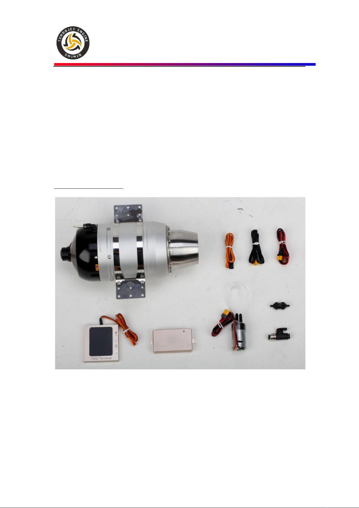
Figure 2 Items Included in Motor Kit ...............................................................................................9
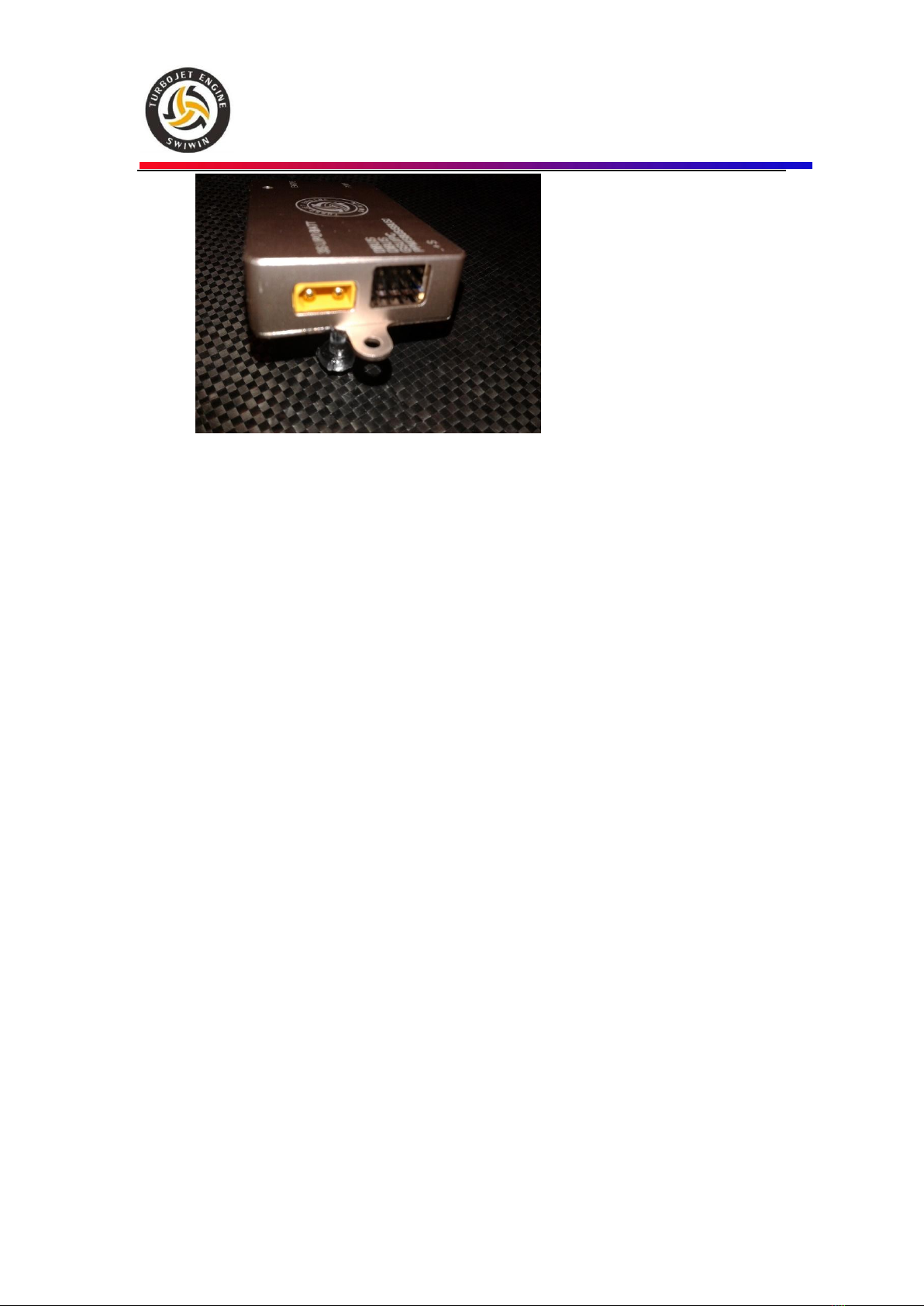
Figure 3 ECU Connections and Power Connection........................................................................10
Figure 4 Engine Connection and Pump ..........................................................................................11
Figure 5 ECU Connections.............................................................................................................11
Figure 6 Engine Cable.....................................................................................................................11
Figure 7 Super Trap Pump..............................................................................................................11
Figure 8 Throttle Line.....................................................................................................................11
Figure 9 Battery Power Cable.........................................................................................................11
Figure 10 Optional Remote Display ...............................................................................................11
Figure 11 GSU................................................................................................................................11

Pg. 4
Figure 12 Brushless Pump ..............................................................................................................12
Figure 13 Motor Setup....................................................................................................................12
Figure 14 Pump Tube Connection...................................................................................................13
Figure 15 ECU/GSU.......................................................................................................................16
Figure 16 SW45B ...........................................................................................................................25
Figure 17 SW60/80B ......................................................................................................................25
Figure 18 SW120/140B ..................................................................................................................26
Figure 19 SW90B ...........................................................................................................................26
SWIWIN USA
Written by CRX Turbines - Andy Fioretti
afioretti@crxturbines.com

Pg. 5
Introduction
This manual is intended to aid the user in setup and running practices associated with the
SWIWIN SW series micro turbines. This manual is not intended to take the place of a
primer on micro-turbines. It is assumed that the user has working knowledge and
experience with turbines and that each user is familiar with best practices before attempting
to run a turbine.
Non- Disclaimer
Turbines are inherently dangerous to run. Please read these instructions completely over
and over then read them over and over AGAIN. You must be entirely familiar with the
operation of this turbine before attempting to run this unit. It is strongly advised that if
this is a first time turbine that the user engage the help of a seasoned pilot or turbine
mechanic in order to help to familiarize the user with the operation and to minimize
potential risks involved. This entails risk to the engine and risk to yourself and any
bystanders.
SWIWIN USA will not take any responsibility for any damages or injury to the user or
bystanders. Our responsibility is explicitly limited to the motor and to the internal
workings and ancillary supplies offered with the turbine.
SWIWIN USA advises ALL users (novice or pro) to test their motors in a test stand before
mounting them in a plane. The reason for this is to familiarize yourself with SWIWIN
motor operation and to ensure reliable operation before mounting the engine in the plane.
If you have any questions, do not run the turbine. If you are unsure about how to
operate the unit, do not run the turbine.
Safety First
Users need to be versed in model jet turbine operation. Purchaser acknowledges the
risks and dangers involved
.
Turbines are potentially hazardous to operate and pose a risk
to the user and any bystanders.
Risk of Explosion
Risk of expelled turbine blades (rear)
Risk of Burns
Risk of long range effect of inhalation of smoke from turbine oil additives
Risk of death or injury due to loss of control of a turbine or turbine propelled
model

Pg. 6
User accepts full responsibility for all risks including those to any bystanders. User
accepts responsibility and bares all risks associated with operation of SWIWIN turbine
engines.
Warning to Bystanders -
User acknowledges the risk of
injury or burns to bystanders during start-up or while
operating a turbine.
User agrees to take all steps
necessary to ensure that all persons are situated a safe
distance from the operations of the engine.
Please refer to figure 1. Always ensure, that all bystanders
maintain a safe distance from the engine. At least 10m (30ft)
clear of the area to the side and rear of the engine, Turbines
rarely catastrophically malfunction but in the rare event of an
issue, it is best to maintain a safe distance.
Fire extinguishers –It is absolutely crucial to have at least one
CO2 extinguisher and a Class ABC extinguisher on hand at all
times. CO2 is the only recommended application for a motor
fire. A dry chemical extinguisher will work to extinguish a fire
but the residue left behind from dry chemical extinguishers
does heavy damage to a running turbine. If a chemical
extinguisher is used to douse a running engine fire, the motor
will need to be completely dissembled and cleaned. The
warranty is void if dry chemical extinguisher is used to put a
turbine fire out.
Important Note: Please be sure to inspect all extinguishers each day that a turbine is being
used. There are countless recounts by pilots and assistants where they reached for a fire
extinguisher and it was not where it needed to be and even worse is an extinguisher that
was not operational.
Failsafe
-
Failsafe. Please read carefully the notes on setting the failsafe on your radio to
ensure safe operation in event of interference or loss of signal.
Ear Protection –Turbines produce excessive Db levels of noise. Always use ear protection
when running the engine.
Burns - Exhaust gases are very hot (up to 1000°C) and can cause burns to skin or damage to
objects close to it –keep exhausts clear of anything which is affected by such heat.
Figure 1 Safe Distance

Pg. 7
Turbine Oil Toxicity - Turbine oil is poisonous. Keep it away from the mouth and eyes and from
contact with skin. Always store it in a marked container and out of reach to children.
Inhalation of Smoke from Turbine Exhaust –Turbine oil is a known carcinogenic. Prolonged
and repeated exposure to turbine exhaust (1when using turbine oil) can be a health
endangerment.
Ground Assistants -
Use a qualified ground assistant during all Start-Up procedures
.
Purchaser agrees to use an assistant who is familiar with the operations of a micro
turbine.
Keep assistants close and be sure that they understand their role before starting the engine.
One assistant should carry out the role of fireman. Ensure that they are aware of what to
do in event of emergency and where to position the extinguishers.
Turbine Oil –Turbine oil is required for operation of your turbine. Use of any
non-approved oil such as 2 cycle oil voids the warranty.
SWIWIN Limited Lifetime Warranty
SWIWIN warrants each turbine to be free from defects in materials and workmanship during
normal usage, according to the following terms and conditions.
1. The warranty is transferable to any subsequent user. There is a $50 admin fee which
will be collected when ownership of the motor is transferred. Please make sure that
each user registers the motor with SWIWIN at the time of transfer so that service can be
maintained on the motor.
2. Warranty period commences on the date of purchase.
3. First year warranty covers all parts except for batteries.
4. Lifetime warranty coverage applies after year one and covers the following items:
a. Combustion chamber
b. Shaft
c. Shaft tunnel
d. Diffuser
e. Injectors
f. NGV
g. Turbine wheel
5. Lifetime Warranty does not cover the following items:
a. Damage to Can
b. Crash Damage –under no circumstance
c. Starter motor
d. Glow Plug
1Turbine oil or Mobil DTE may be used for lubrication purposes.

Pg. 8
e. Any FOD damage including and not limited to:
i. Broken compressor blades
ii. Scored intake cover
f. Diffuser
g. Solenoid/valves
h. Pump
i. ECU
j. GSU
Terms
1. Within the initial 1 year warranty period, SWIWIN will repair or replace, at SWIWIN’s
discretion, any defective part(s), with new or factory rebuilt replacement items if such
repair or replacement is required and is due to a malfunction during normal usage.
2. SWIWIN will cover labor charges associated with any warranty repair.
3. SWIWIN warranty coverage is limited to replacement of parts and repair of the unit and
does not apply to any other losses or damages, consequential or inconsequential to the
failure.
4. Buyer is required to register the motor with SWIWIN at the time of purchase. Please
retain all receipts and paper work.
5. Buyer agrees to cover the cost of shipping the turbine to SWIWIN USA for repair.
Exclusions
6. Warranty and/or extended coverage does not apply under the following circumstances:
a. The turbine is used for commercial or institutional (school) use
b. The turbine has been stored improperly
c. The turbine was submerged in water
d. The turbine has been modified in any fashion
e. Any attempt to repair
f. Any dismantling of the turbine
g. Any crash regardless of cause
h. The turbine was not cooled properly
i. Improper electrical connections
j. Turbine serial number has been removed or altered.
k. Turbine is found to have been operated with 2 cycle oil
7. If a problem occurs during the warranty period, please contact our service department
and take the following steps:
a. Contact SWIWIN in order to coordinate shipping of the turbine to the service
center for evaluation and repair.
b. Send the turbine to our repair center. Please include all user information
including address and daytime phone number, email address, etc. Please also

Pg. 9
include a photo copy of the original sales receipt.
8. Owner agrees to cover charges for all parts and/or labor charges not covered by this
warranty.
9. In the event that a turbine is returned and it is later determined that the engine has
failed due to issues that are not covered under the warranty (see above conditions) the
owner will be provided with a repair estimate.
l. If the estimate is refused, the turbine will be returned to the user. Owner
agrees to cover all return shipping costs.
10. This document constitutes the entire warranty between SWIWIN and the owner and
supersedes all prior agreements and/or understandings.
Operation and Setup
Figure 2 Items Included in Motor Kit
Please refer to Figure 3 below for steps 1 and 2
1. Refer to Figure 3 below. Connect one end of the RJ45 black data cable (provided) to
the motor receptacle. Connect the other end of the black RJ45 cable to the ECU
connection labeled “Sensor Cable”
2. Connect the yellow power cable (Male) to the ECU port labeled “Power Cable”.

Pg. 10
Figure 3 ECU Connections and Power Connection
Refer to Figure 4 below for steps 3 and 4.
3. Connect one end of the servo cable (provided) between the ECU port labeled
“Throttle” and the other end to your receiver #3 input.
Please note “S” signal and “-“ on ECU polarity. The ECU and/or GSU will
not function properly if not connected properly.
4. Connect the battery cable to ECU port labeled “Battery”. The battery connector
can be deans or XT60 type.
5. Connect the pump (deans) to the pump cable and the other end to the ECU port
labeled “pump”.
6. Connect the GSU to the ECU port labeled GSU. Orange signal toward top of ECU.
Please observe correct polarity or the terminal will not operate properly.

Pg. 11
Figure 4 Engine Connection and Pump
Figure 5 ECU Connections
Figure 6 Engine Cable
Figure 7 Super Trap Pump
Figure 8 Throttle Line
Figure 9 Battery Power Cable
Figure 10 Optional Remote Display
Figure 11 GSU

Pg. 12
Figure 12 Brushless Pump
Figure 13 Motor Setup
Motor Setup
Introduction –for first time users and for first time use of any engine, it is strongly
recommended that the motor be placed into a test stand for the first time. There are a hundred
reasons to do this. There is only one good reason to mount a brand new motor into a plane for
the first start time and the answer is there is no benefit. I have had countess discussions with
people who have spent hours or days to install a new engine and all the ancillaries then have to
undo their work to test the motor because of startup issues. There is just no upside to not
taking the time to adequately test the engine before putting it into a plane.
Mount the engine in a test stand that will minimally handle the full thrust of the engine. This
means secure it properly and weight the table if needed. A workmate bench can work for a
small 60 sized engine but is not suitable for securing a larger engine. Mount the engine securely

Pg. 13
into whatever apparatus you select. Do not do this indoors. Do route the exhaust outdoors or
into a pipe that goes outdoors. Mount the ancillaries neatly where you can see them. Do not
skimp on this step. Note the orientation of the parts and the plumbing. Make sure the valve is
off. Then work on the electrical. It is difficult to mix up polarity with all of the enhancements
to the wiring we provide now but depending on how you are supplying LiPo current please
observe correct polarity to the ECU. If you mix up polarity on the LiPo end, the ecu will instantly
be fried. There is no warranty on a fried ecu so please observe correct polarity.
Please refer to Figure 13 - Motor Setup above
1. Connect the motor festo fitting to a section of 4mm tubing (included).
2. Route the tubing to the filter then to the shut off as shown.
3. Connect the other end of the shutoff with 4mm tubing to the output of the
supertrap pump.
4. Plumb the UAT as shown and per the UAT instructions (UAT is not included)
5. Plumb the Fuel tank per the manufacturer instructions noting orientation above.
6. Connect Input of fuel pump to UAT fuel out fitting
7. Double check your fittings
8. Use 20 gauge stainless wire to secure tubing to non-festo connections
Figure 14 Pump Tube Connection
Radio Setup and Training –Learn RC
Refer to Learn RC below. It may take some getting used to the functions of the GSU. Highlight
maximum on the GSU, raise the radio stick and trim to max. Note the signal level changes as
you raise stick and trim. Depress OK to lock in the new “maximum” value.
Highlight Idle on the GSU and lower the stick while leaving trim at maximum level. Depress Ok
and lock in the “idle”value
Highlight Minimum on the GSU and lower the trim to a value you select as stop. The stick

Pg. 14
should be at minimum now. Press Ok to lock in the “minimum” value.
Servo Tester in Place of a Radio
For test purposes, a servo tester can be used in place of a radio. The use of a servo tester
provides a means to isolate the motor especially if there are any suspected radio issues.
Ensuring that the engine works properly first is a good measure. The setup and utilize a servo
tester, refer to the radio setup. Maximum is maximum signal out for the tester. Minimum or
stop is set to the lowest output of the tester and idle is a value in-between which is arbitrary and
up the user.
Priming the Pump
Before using the turbine for the first time it is imperative to prime the pump and remove all
air from the lines before attempting to start the engine.
To prime the pump:
1. Connect a section of fuel line to the input of the pump and to a vessel with fuel in it
2. Connect another section of fuel line to from the output of the pump to the same
vessel. This will establish a loop.
3. Initiate the test pump function by going to the main screen then stepping down to
“test”. Select the first option “test pump”. With the OK button depressed the
pump will gradually begin to spin faster and faster until a steady stream of fuel can
be seen entering back into the vessel. Be sure all air bubbles have been expelled
from the fuel line.
4. Once the operation is complete remove fuel line from the vessel and install on the
motor.
Note: Some users report running the pump for a few minutes with fuel circulating to “break
in” the pump before running the engine for the first time.
Startup Operation
Prior to running the turbine walk around the aircraft or motor stand and make sure that all
power and data connections are placed properly.
1. Turn the fuel valve to the on position
2. Turn on power to the receiver and observe GSU startup. The motor and GSU will
sync up with an audible signal.
3. Turn on power to the Radio Controller. Note an audible sync tune when the radio is
powered up. This lets the user know that the motor is online with connection to

Pg. 15
the radio.
4. Turn on the fuel valve.
5. Raise the trim to 100% and observe ECU status switches from stop to “ready”.If
the ECU does not transition to ready state, recheck the ECU to radio connection and
retrain if needed.
6. Raise the throttle stick to full then to min. This will initiate a start sequence.
7. The starter motor will begin to spin. The ECU will switch to ignition, then to
preheat, then to ramp.
oIgnition - This is the first phase of startup. During the ignition phase, there
is a minimal flow of fuel (based on pump voltage you select) to the plug.
During ignition, listen for a sizzling sound. This occurs as fuel begins to flow
across the white hot glowplug. As heat increases, the engine will then
transition to preheat. View the transition on the screen. Temperature
should be on a continuous rise.
oPreheat –As the engine transitions to “preheat” the motor will increase rpm
to the value set in the startup menu –“preheat RPM”. Fuel continues to
flow through the plug based on the value set in “gas valve”. At this time,
the main jets begin to flow fuel.
Note: Depending on the software release of your engine, a main
“fuel Valve” setting may not be visible in the startup values. This
parameter has been eliminated on newer releases.
oFuelramp –After the motor has reached a suitable heat level, the motor
enters the “Fuelramp” phase. The motor begins to ramp and the pump
begins to pump more and more aggressively. The rate at which the engine
increases speed is based on the startup value set in “percentage fuel ramp”.
Higher numbers equate to a faster start sequence but it is advised to be
conservative when changing ramp values.
Tip: Adjust pump start, ramp start and % ramp to fine tune the startup.
Please note that these values have no effect on the running state of the
engine.
After the motor reaches idle speed the ECU will train to the motor. For first
time only use, the ECU will display a message to “raise stick”. Raise the stick
to full and allow the motor time to reach full output. Next, the ecu display
“lower stick”. Lower the stick (not the trim) to minimum. After the motor
reaches idle speed, the ECU will transfer control to the user and switch to
“running” status.
Note: the actual messages displayed may be different depending on the
software revision. Please refer to the notes regarding specific software
First time use

Pg. 16
revisions.
Shutdown Procedure
Always observe proper shutdown and cooling of the turbine. Failure to observe proper
shutdown by not properly cooling the unit will render damage and will void the warranty.
Shut down the turbine
1. Lower the stick to minimum
2. Lower trim to minimum
3. As trim is lowered to the threshold initially set, the motor will shut down and initiate
a cool down sequence by turning on the starter motor to an RPM defined in motor
parameters. This cool down speed is determined in cooling menu of ECU setup.
The default cool down speed is 7000 rpm. Depending on the software release the
engine may turn continuously until a safe temperature is reached or with brushed
starters the starter engages intermittently until the engine is cooled (80C).
4. Turn off the fuel
5. Turn off power to the controller
6. Turn off power to your radio
ECU
The SWIWIN ECU was designed from the ground up and is based on 32 bit microprocessor
functionality and designed specifically for SWIWIN Turbines.
Figure 15 ECU/GSU
The ECU offers the following benefits:

Pg. 17
Data Logging
Auto start
Automatic Restart
Color Screen visible in direct sunlight
Configurable thrust curve with very fast throttle response
ECU/Motor Electrical Connections
Do not exceed these voltages!
Receiver voltage:5-8.4V(5S Nimh or 2S Life or 2S Lipo)
Power voltage:9.9-11.1V (3S Life or 3S Lipo)
GSU Screen Button Function
“OK” Invoke a change or command
“C” Clear a screen
“+” Increment a value
“-“Decrement a value
Initial Screen
RPM –Current running status of the
turbine
Temp –Current temperature of engine
Curr –Electrical current in use
Cap –Main Battery that has been used
ACC –Response time from idle to max. in
seconds.
Screen Bottom –Running Status
RPM - 0 –100%
Temp - 0 –1000 Celsius
Pump –output measured in volts –ex.

Pg. 18
4300/1000 = 4.3 volts
RC –throttle position from 0 –100%
Large font Running Screen
Press “C” to toggle between large screen
and normal
Main menu –initial screen
From the initial screen, press “OK” key,
click “C”to toggle back to boot screen
StartUp –enter startup menu
Adjust RC –Train Radio to ECU
Cooling –set cooling rpm
Running –enter Running menu
Other –enter other parameters menu
Test –enter Test menu
Language - switchable Chinese or English
*DispAllMenu –select to show all hidden
menu –see next pic for all menu screen.
*This screen omitted on recent releases
Start Up Screen (advanced functions)
PumpVoltage - Set pump voltage Typical
value is from .4 to .5. This sets the
initial pump volume when the motor is
initially started. The flow should be a
drip, drip, drip.. not a heavy flow at all.
Test over a piece of rag or a canister.
Pump Voltage, Pump Auto, ramp,
startup ramp and Ramp Percent values
have zero effect on the engine after the
engine is running.

Pg. 19
Each pump is different even for the same
brand of pump. .2 - .8 is a huge change.
Make adjustments .02 - .04 increments at
a time.
RPM StartUp Ramp –Set ramp profile –On
new engines please follow the default
parameters. Once familiar you can raise
this value in order to speed the start time
of the turbine. Typical values from 60 –
80%
PumpStartUp Ramp - This parameter
adjusts the speed of the fuel increase
during the “Fuel ramp” phase. Higher
values mean a faster fuel flow increase.
Increase this value if the engine takes too
long to arrive to idle, and decrease it if the
starts are too hot, with the engine
overshooting the idle speed. Typical values
from 0 –5.
Pump Auto - Sets the power of the pump
when it is started at beginning of the fuel
ramp. The ECU has the ability to
automatically adjust the pump power to
start it at the lowest possible speed.
Typical values from -5 –0.
GlowPlug –Set Glow Plug Voltage. Typical
value from 6.0 to 6.8. Set this to the
lowest value to achieve a reliable start.
GasValve and Fuel Valve - Set the
percentage of time of the main fuel valve
is open at beginning of the switchover
phase. This percentage will increase
automatically with RPM until arrive to fully
open when the RPM of next phase are
reached. The time where the burner valve
is open is complementary to the injector
time, so when the main valve is open at
80%, the burner is 20%. Typical value
50%-70% Please note recent software
revisions may have removed the main
valve setting.
Ignition RPM –Set the RPM where ignition

Pg. 20
phase commences
Preheat RPM –Set the RPM value for
preheat phase to begin.
RPM Starter Off –Set the RPM where the
starter motor will disengage.
Learn RC
This menu is to train the transmitter to the
ECU. Be sure to depress OK to lock in the
value that you select.
Max –Throttle up, trim up
Idle –Throttle down, trim up
Min –Throttle down, trim down
FailSafeTime –set fail safe time in seconds
Cooling
Sets the cooling rpm after shut down or
when starter is manually run using test
functions.
*Please note that following a failsafe
failure or flameout that the motor will not
automatically enter a cool down sequence.
This is because the ECU has no way of
knowing the status of the motor whether
flame out, crash or other.
This manual suits for next models
11
Table of contents
Popular Industrial Equipment manuals by other brands

Endress+Hauser
Endress+Hauser Teqwave F/I Brief operating instructions

Graco
Graco PR-X Setup - Operation - Repair

Regulus
Regulus RGMAT E G60 Installation and operation manual

M-system
M-system M8BS-16K2 instruction manual

Flott
Flott TS 150 SW operating instructions

Rexnord
Rexnord FALK HF132 Installation & maintenance