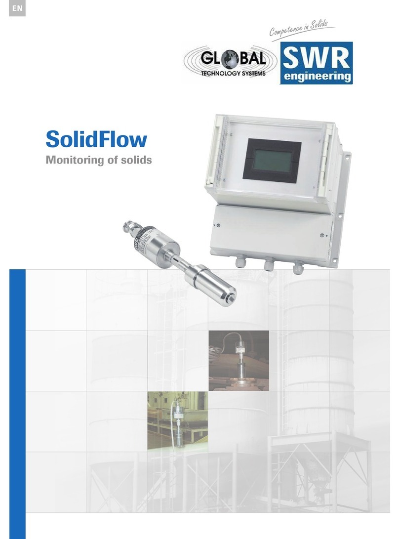
SWR ENGINEERING SOLIDFLOW User manual

BA-0003-e-03/02
SOLIDFLOW
SWR engineering
Messtechnik GmbH
Mittlerer Weg 22
D -79424 Auggen
Germany
Tel +49 7631 10501
Fax +49 7631 10502
eMail info@swr-engineering.com
Operating
Instructions

System overview
Page 2
1. SYSTEM OVERVIEW 4
2. FUNCTION 5
3. SAFETY 6
3.1 Regular use 6
3.2 Identification of dangers 6
3.3 Operational safety 6
3.4 Technical progress 6
4. MOUNTING AND INSTALLATION 7
4.1 Delivery range 7
4.2 Auxiliary 7
4.3 Mounting of the sensor 7
4.4 Mounting of the transmitter unit 10
5. ELECTRICAL CONNECTION 11
5.1 Connection of the separated version 11
5.2 Flow diagram of the separated version 12
5.3 Connection compact version 13
5.4 Flow diagram of the compact version 14
6. COMMISSIONING 15
7. OPERATION 17
7.1 Operating elements 17
7.2 Adjusting the output signal 17
7.3 Adjusting the parameters for the measurement value alarm 18
7.4 Filter adjustments 18
8. MAINTENANCE 19
9. WARRANTY 19
10. TROUBLE SHOOTING 20

System overview
Page 3
11. TECHNICAL DATA 21

System overview
Page 4
1. System overview
Overview of the measuring system separated version
++
Overview of the measuring system compact version
+
←Max. 1.5 m →←up to 1000 m →
sensor pre-amplifier evaluation unit
←Max. 1.5 m →
sensor evaluation unit

Function
Page 5
2. Function
SolidFlow is a measuring system especially developed for measuring the flow rate of pneumatically
conveyed solids in metallic ducts.
The microwave energy is being back scattered by the solid particles and received by the sensor. These
signals are evaluated in frequency and amplitude. Because of the selective frequency evaluation only
moving particles are measured.
The measuring signal is independent of pressure and temperature in the duct. A measuring unit consists
of one or two sensors, a pre-amplifier and the evaluation unit.
Fig. 3: Coupling and reflection of the microwaves.

Safety
Page 6
3. Safety
The measuring system SolidFlow was designed, built and tested to be safe and was shipped in safe
condition. Nevertheless persons or objects may be endangered by components of the system if these
are operated in an inexpert manner. Therefore the operational instructions must be read completely and
the safety notes must be followed.
In case of inexpert or irregular use, the manufacturer will refuse any liability or guarantee.
3.1 Regular use
The measuring system must be installed for measuring the flow rate in metallic ducts only. Other usages and
modifications of the measuring system are not permitted.
Only original spare parts and accessories of SWR engineering must be used.
3.2 Identification of dangers
Possible dangers when using the measuring system are marked by the following symbols in the
operating instructions:
Warning!
This symbol in the operating instructions marks actions, which may represent a danger for life and limb
of persons when carried out in an inexpert manner.
Attention!
All actions which may endanger objects are marked with this symbol in the operating instructions.
3.3 Operational safety
The measuring system must be installed by trained and authorised personnel only.
Switch off the supply voltage for all maintenance, cleaning or inspection works on the tubes or on
components of the SolidFlow. Follow the notes of the chapter maintenance.
The components and electrical connections must be checked for damages regularly. If damage is found,
it is to be repaired before further operation of the instruments.
3.4 Technical progress
The manufacturer reserves the right to adapt technical data to the technical progress without particular
advance notice. If you have any questions, SWR engineering will be pleased to inform you on possible
changes and extensions of the operating instructions.

Mounting and installation
Page 7
4. Mounting and installation
4.1 Delivery range
•Evaluation unit, version as ordered.
•Weld on sensor accommodation.
•Hook wrench for the union nut.
•Sensor, prepared to the wall thickness (union nut, distance washers, seal-ring).
•Operating instructions.
4.2 Auxiliary
•Drill Ø 20 mm for steel.
•Pliers for circlips (Ø 20 mm) for adjusting the wall thickness at the sensor.
4.3 Mounting of the sensor
The sensor is to be mounted as follows:
•Determine the place of mounting on the duct. On horizontal or inclined ducts the sensor should be
mounted from top.
•In case of duct diameters greater than Ø 150 mm (6”) or aspecial application one has to install 2
sensors which are located 300 mm (12”) apart from each other and moved by 90° towards each
other.
•Follow the necessary distances of valves, bows, fans or cellular wheel sluices etc. and also other
measurement devices like temperature and pressure etc. to the sensor (see fig. 4).
Fig. 4: Minimal distances of the sensor to duct
bends and baffles.

Mounting and installation
Page 8
•Weld the sensor accommodation on to the duct.
•Drill the Ø 20 mm hole into the duct. Please use your own drill as there are different shafts
available. Take care that the hole is in line and rectangular to the surface to avoid trouble by
inserting the sensor.
•If the sensor is not installed immediately, the dummy plug must be put in until the sensor will be
installed (see fig. 5). Use the delivered hook wrench for tightening the union nut.
Fig. 5: Installation of the sensor accommodation and the dummy plug.
•Remove the dummy plug for installing the sensor.
•The sensor will be delivered prepared to the required wall thickness if known and ordered otherwise
the sensor comes prepared for 5 mm wall thickness. We strongly recommend that the correct
adjusting is checked again, see table, if necessary the wall thickness must checked with a depth
gauge. It is important that the sensor does not intrude into the duct because the front end of the
sensor will be worn by abrasion otherwise. The sensor may be submerged into the duct wall by up
to 1 mm without creating an error of measurement.
Wall thickness [mm] Circlip for shafts
position
(Fig.6a Pos.2)
Number of
distance washers
(Fig.6a Pos.3)
4.0
5.0
6.0
7.0
8.0
9.0
10.0
11.0
12.0
1
3
3
3
3
3
5
5
5
-
4
3
2
1
-
3
2
1
1union nut
2circlip for shafts
3distance washer 1 mm
4O-ring-type sealing ring
5not applicable
6sensor accommodation
7dummy plug
8headless screw 3 mm (only by
St52 steel design)

Mounting and installation
Page 9
•Now the sensor is put into the sensor accommodation and screwed with the union nut according to
figure 6a.
Fig. 6a: Installation of sensor accommodation and sensor.
•Look at the POLARISATION –label to adjust the sensor along to the duct, fig. 6b. Lock the sensor
with the union nut dust proof and fix the sensor with the headless screw against turning around.
Fig. 6b: Adjustment of the sensor
1union nut
2circlip for shafts
3distance washer(s) 1mm
4O-ring type sealing ring
5not applicable
6sensor accommodation
7sensor
8headless screw 3 mm
9guide washer 1mm

Mounting and installation
Page 10
4.4 Mounting of the transmitter unit
The transmitter unit is available in two versions:
As compact version:
All the electronic equipment (power supply, pre-amplifier and evaluation unit in one field housing) can
be installed at a maximum distance of 1.5 m from the sensor. The housing is prepared for wall
mounting. For mounting dimensions see technical data.
Fig. 7: Field housing
As separated version:
The pre-amplifier is installed at a distance of 1.5 m from the sensor, power unit and evaluation unit can
be installed in a measuring station or in a control box at a maximum distance of 1,000 m (Cable
specification: 4 wires used, min. 0.5 mm² wire cross section, single shielded, recommended cable type
LiYCY 8*0.5 mm2;RD-Y(St)Y 4*2*0.5 mm2or equal quality).
The pre-amplifier can be put on a standard rail (EN 5002) or is delivered in a housing prepared for wall
mounting. The mounting dimensions are shown in fig. 8. For mounting dimensions see technical data,
for the housing of the evaluation unit see fig. 7.
Fig. 8: Pre-amplifier housing
Other manuals for SOLIDFLOW
1
Table of contents
Other SWR ENGINEERING Measuring Instrument manuals
Popular Measuring Instrument manuals by other brands

Endress+Hauser
Endress+Hauser Promag 300 installation instructions

Vibration Research
Vibration Research ObserVR1000 quick start guide

Scientific
Scientific SM6020 user manual

PCB Piezotronics
PCB Piezotronics IMI SENSORS 623C00 Installation and operating manual

TECPEL
TECPEL DPM 035 quick start guide

Fungilab
Fungilab EVO Series instruction manual