SX BLUE GPS NET20 PRO User manual

CORS REFERENCE STATION RECEIVER
High performance
NET20 PRO
User Manual

2 3
Content
1 Technical Specication............................................................................................ 5
1.1 Overview............................................................................................................................................................................ 5
1.2 Main features.................................................................................................................................................................... 5
1.3 Technical Specication.................................................................................................................................................. 5
1.3.1 Physical .................................................................................................................................................................. 5
1.3.2 Environmental ...................................................................................................................................................... 5
1.3.3 Electrical ................................................................................................................................................................. 5
1.3.4 GNSS....................................................................................................................................................................... 6
1.3.5 Ports ........................................................................................................................................................................ 7
1.3.6 Data and Storage................................................................................................................................................ 7
2 Hardware Structure ................................................................................................. 8
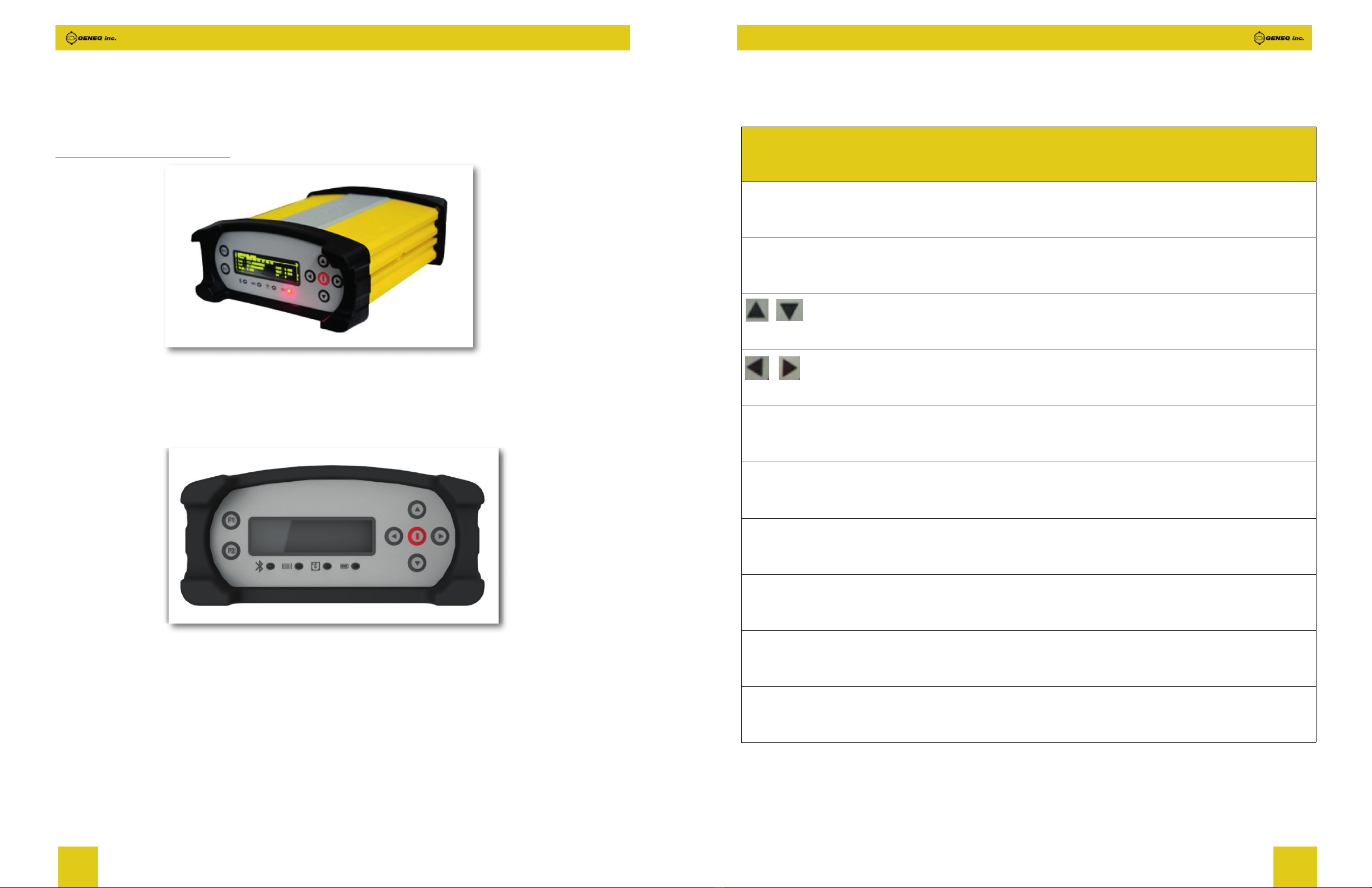
2.1 Receiver appearance..................................................................................................................................................... 8
2.1.1 Front panel ............................................................................................................................................................ 8
2.1.2 Back panel............................................................................................................................................................. 10
2.2 Structural drawings / mounting dimensions ......................................................................................................... 11
3 WEB UI ....................................................................................................................... 12
3.1 Summary............................................................................................................................................................................ 12
3.2 System Information ........................................................................................................................................................ 13
3.2 1 System Information............................................................................................................................................ 13
3.2.2 GPS Status............................................................................................................................................................ 13
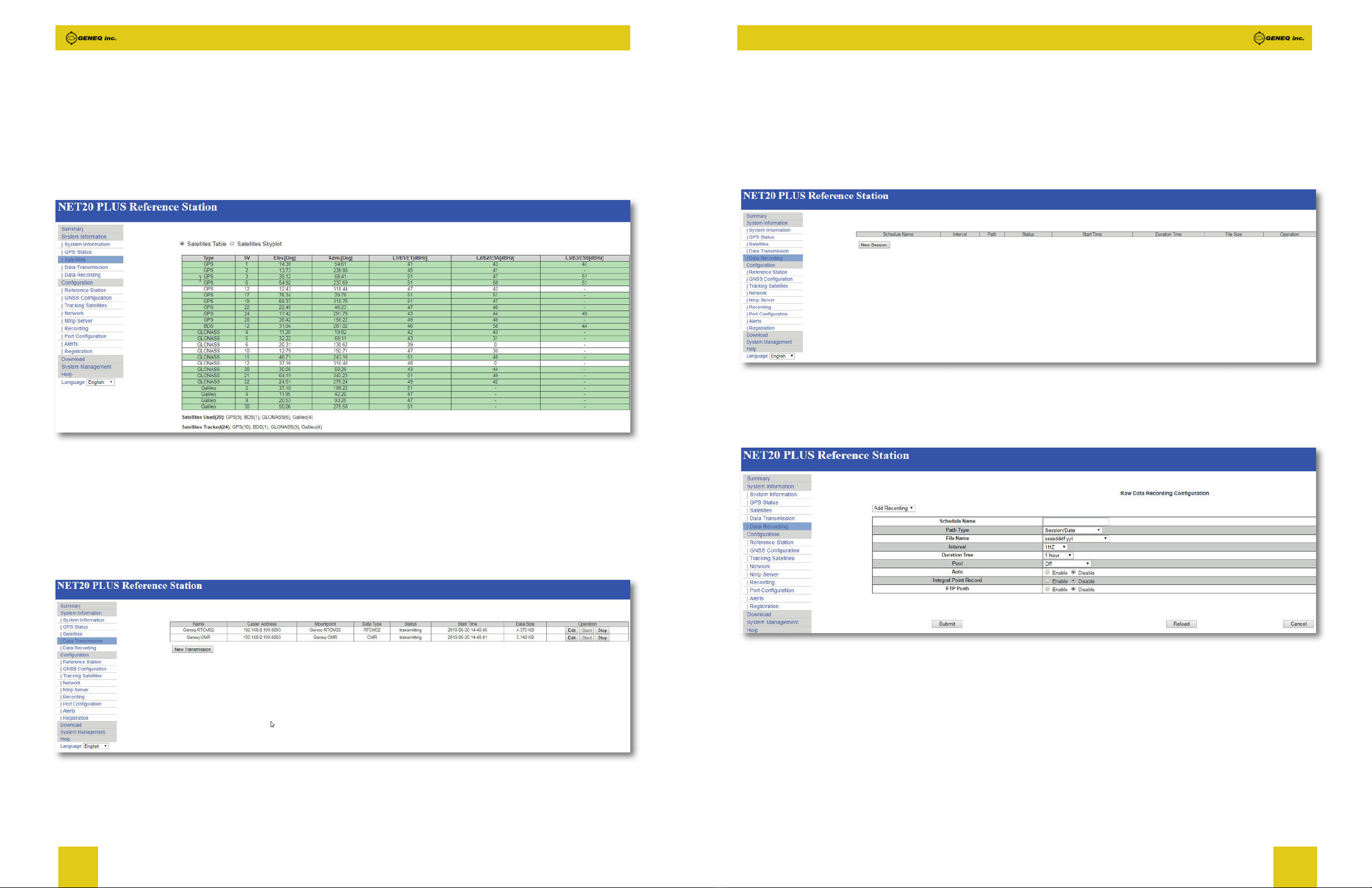
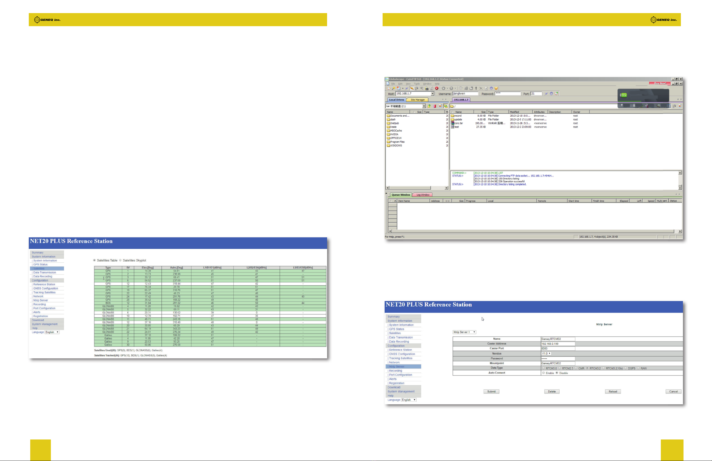
3.2.3 Satellites................................................................................................................................................................. 14
3.2.4 Data Transmission.............................................................................................................................................. 14
3.2.5 Data Recording.................................................................................................................................................... 15
3.3 Conguration.................................................................................................................................................................... 16
3.3.1 Reference Station ............................................................................................................................................... 16
3.3.2 GNSS conguration ........................................................................................................................................... 17
3.3.3 Tracking satellites ............................................................................................................................................... 17
3.3.4 Network.................................................................................................................................................................. 18
3.3.5 Ntrip Server........................................................................................................................................................... 19
3.3.6 Recording............................................................................................................................................................... 20
3.3.7 Port Conguration .............................................................................................................................................. 21
3.3.8 Alerts....................................................................................................................................................................... 22
3.3.9 Registration........................................................................................................................................................... 23
Statement
Please read carefully :
The nal interpretation of this user manual belong to Geneq.
This user manual is only for your reference. If your receiver does not match the case in user manual,
the actual situation of the receiver shall prevail.
Information in this document is subject to change without notice; Geneq reserves the right to change
or improve its products and to make changes in the content without obligation to notify any person or
organization of such changes or improvements. If you have any questions, please contact customer
service center, or contact our authorized dealers.
Please carefully read the notes and instructions in User Manual. In order to avoid unexpected damage,
you should only use original supplied parts. If you do not use the system with the correct procedure
or connect incompatible accessories, cause the equipment damage and may even endanger other
person and your safety. In this regard, the Company does not assume any responsibility.

4 5
1 Technical Specification
1.1 Overview
NET20 PLUS is a high-precision CORS reference station receiver. LINUX system as its development
platform, and it support for secondary development. It has powerful and stable function, and can be
used in many elds.
1.2 Main features
• 555 channels with Multi-constellation GNSS support.
• Superior carrier phase observations of less than 1mm accuracy.
• Internal battery for more than 20 hours operation.
• 4G LTE and Bluetooth / WLAN datalink support.
• Easy conguration from Web UI and remote server.
• NTRIP server/caster support.
1.3 Technical Specification
1.3.1 Physical
• Weight : 2KG
• Dimension : 222mm*164mm*79mm
1.3.2 Environmental
(1) Operating temperature : -30°C-60°C
(2) Storage temperature : -40°C-80°C
(3) Humidity : 0 %-100 % non-condensing
1.3.3 Electrical
(1) Input : 9-28V
(2) Power : 2.8W
3.4 Download .......................................................................................................................................................................... 23
3.5 System Management .................................................................................................................................................... 24
3.6 Help ..................................................................................................................................................................................... 24
4 Operation ................................................................................................................... 25
4.1 Power on............................................................................................................................................................................ 25
4.2 Quick setting..................................................................................................................................................................... 26
5 Accessories ................................................................................................................ 32

6 7
1.3.5 Ports
(1) 3 RS232 serial ports(DB9 and 2 LEMO 5pin).
(2) 1 RJ45 Ethernet port.
(3) 1 power port.
(4) 1 USB port.
(5) 1 4G LTE antenna port.
(6) 1 UHF antenna port.(Optional)
(7) 1 EVENT port.
(8) 1 1PPS port.
(9) 1 SIM card slot.
(10) 1 GNSS antenna port.
1.3.6 Data and Storage
(1) Output data format : NMEA-0183, binary, RINEX, RTCM2.x, RTCM3.x
(2) Internal memory : 32G
(3) External storage : 32G
1.3.4 GNSS
(1) Channels : 555
(2) Tracking signals :
• GPS : L1 C/A, L1C, L2C, L2P, L5
• GLONASS : L1 C/A, L2C, L2P, L3, L5
• BeiDou : B1, B2, B3
• Galileo : E1, E5 AltBOC, E5a, E5b, E6
• IRNSS : L5
• SBAS : L1, L5
• QZSS : L1 C/A, L1C, L2C, L5, L6
• L-Band up to 5 channels
(3) Positioning accuracy
Table 1-1 Positioning accuracy
Positioning mode Accuracy
Horizontal Vertical
Static 5mm 10mm
RTK 1cm + 1ppm 2cm + 1ppm
(4) initialization time : < 10s
(5) initialization reliability : > 99.9 %

8 9
Table 2-1 Function table
Name Function
F1
Save the current setup and return to the previous menu
F2
Enter the main menu
Move the cursor up and down, modify parameters when entering modify items
Move the cursor left and right
Power key
Switch on/off the receiver and con rmation key
Power Off
Press once until “Shut Down” , press second time
Bluetooth indicator
It will be light blue when NET20 PLUS is connected via Bluetooth
Differential
transmission indicator
When the differential data output, the differential indicator blinks evenly at 1-second
interval
Static recording
indicator
When start static recording, static recording indicator blinks evenly at 1-second interval
Power indicator
After switching on NET20 PLUS receiver, the power light is normal on
2 Hardware Structure
2.1 Receiver appearance
Figure 2-1
2.1.1 Front panel
The front panel of NET20 PLUS receiver includes seven buttons, four LED indicators, and one OLED
display.
Figure 2-2
After switching ON NET20 PLUS receiver, current time information, GPS status displayed in the main
interface. The default language is English, and you can press the left and right arrow keys to obtain
the current IP information.

10 11
2.2 Structural drawings / mounting dimensions
Figure 2-4
2.1.2 Back panel
NET20 PLUS receiver provides a variety of communication interfaces to facilitate users in different
application scenarios.
Figure 2-3 Back panel
Table 2-2 Interface function table
No. Name Function
1PWR Receiver power supply interface, input voltage DC 9V-28V.
2USB USB interface
3COM1 RS232 serial port
4COM2 RS232 serial port(Optional RS485 serial port)
5COM3 DB9 serial port
6LT E GPRS antenna interface
71PPS 1 Pulse Per Second output
8EVENT EVENT input
9SIM Standard size SIM card interface
10 RJ45 Wired Ethernet port
11 GNSS GNSS External receiver antenna connector
12 UHF UHF External receiver antenna connector
Note :
The UHF interface is replaced by the OSC interface in the NET20 PLUS.

12 13
3.2 System Information
3.2.1 System Information
In the system information screen will display the station name, device model, body number, system
version, application version information, built-in OEM board models, and network parameter
information.
Figure 3-2
3.2.2 GPS Status
Status page displays the current NET20 PLUS positioned state, the base station coordinates and
antenna type usage.
3 WEB UI
There are two ways to login the WEB interface, which are Ethernet port login and WIFI login. The
WEB interface content of the two login modes is same.
(1) Ethernet port login : Connect the RJ45 network port with the computer host, and enter the IP on
the NET20 PLUS display in the browser for NET20 PLUS access. Enter the user name and password
in the pop-up dialog box, and the default username and password are : admin - password.
(2) WIFI login : When NET20 PLUS opens WIFI hotspot, the user can login the browser by connecting
the WIFI. The hotspot name is the serial number of the fuselage. Enter the IP address : 192.168.10.1.
A window will pop up when the user log in, which need to ll in the account and password, and the
default username and password is admin : password.
3.1 Summary
After authentication information to log into the web interface of NET20 PLUS. Home page contents
Reference information, device version, system version, network parameters, memory status and so
on. It is shown as below :
Figure 3-1
Note : The effect of different browsers display may be slightly different, recommend using Google
Chrome or IE.

14 15
3.2.5 Data Recording
In this page, the user can see the speci c data record information as shown in gure 3-6. Click [Edit],
the user could modify the parameters like path type, le name, interval, duration time, etc. As shown
in gure 3-7.
Figure 3-6
Figure 3-7
3.2.3 Satellites
This page shows the satellite signal-to-noise ratio of the current search, elevation mask angle,
azimuth and other information. The information of GPS, BEIDOU, Galileo and GLONASS are displayed
separately.
Figure 3-4
3.2.4 Data Transmission
After setting up the data transmission, the user can see the current data transfer status on the page
as shown in gure 3-5. Click [Edit] to directly jump to [Ntrip Server].
Figure 3-5

16 17
3.3.2 GNSS configuration
This page is mainly set for the satellite systems and the cutoff angle, as shown in gure 3-9.
Figure 3-9
3.3.3 Tracking satellites
In this page, the user can select the satellites they want to track, as shown in gure 3-10.
Figure 3-10
3.3 Configuration
3.3.1 Reference Station
This page mainly sets the reference station, antenna, and reference station parameters, as shown in
gure 3-8.
Figure 3-8
Reference station coordinates : If you do not need a known coordinate to start reference station,
then click the “Load Current Position” as a reference station coordinate. However, if you need a
known coordinate to start reference station, please input the known point coordinates in accordance
with the appropriate format. The web access port is 80. After setting mapping in the router device,
then you can access the NET20 PLUS by Internet.

18 19
If anonymous access is turned off, you need permission to enter the user name and password. After
using the FTP tool to connect NET20 PLUS, the data appears as follows :
Figure 3-12
3.3.5 Ntrip Server
In this page, the user could set the transmission content and the server for the NET20 PLUS reference
station.
Figure 3-13
3.3.4 Network
This page is mainly set for the data link method used by NET20 PLUS, as shown in gure 3-11.
DHCP : If the model DHCP is enable, the NET20 PLUS receiver will auto get IP address, otherwise it
uses the static IP.
WIFI hotspot : After power on WIFI hotspot, then you can use other devices with WIFI function to
search and connect to this NET20 PLUS receiver. The hotspot is named by driver serial. You don’t
need to input password when connect to the WIFI hotspot. Access NET20 PLUS by IP address
192.168.10.1. The hotspot only play the role of control and can’t access internet.
WIFI Client : When selecting WIFI client, in SSID box input a name of WIFI hotspot can be used for
the search, and in the Password box input the password for connecting to WIFI hotspot, then submit.
After connecting to the connection WIFI, the password can be seen in system terminal or panel
interface (the displayed place will be different in different versions).
Mobile network : After starting the mobile network, enter the function mode supported by the SIM
card; NET20 PLUS supports 4G netcom. Users can set the user name and password as needed.
Figure 3-11
FTP download : You can set the parameters of the FTP download. If anonymous access is turned on,
it does not require a user name and password to connect to the NET20 PLUS for FTP downloading.

20 21
Table 3-1 The rule of Static record le name
File name Annotation
YYYYMMDDhhmmss.dat Date and when, minute and second
YYYYMMDDhhmm.dat Date and when, minute
DOYhhmm.dat Day of year, hour and minute
YYYYDOY?.dat Year, day of year, period of time
ssssdddf.yyt Station name, day of year, period of time
Rinex302.dat Named by rinex3.02 standard
Custom Manually input the le name by the way of name + .dat
Duration time : After setting the record length, the le will be recorded depending on the setting
time, and it will be stopped recording at the end of the record length. If you turn on the auto record,
the NET every record length, or it need to be manually start recording.
FTP push : First you should set the FTP server parameters. When it records the data to the internal
memory, NET20 PLUS will also send the data to FTP server automatically.
3.3.7 Port Configuration
Port setting includes Bluetooth port, COM1 port and Socket settings. They can support the function
as follow :
CMD (INPUT/OUTPUT) : Instruction NET20 PLUS
NMEA (OUTPUT) : Output Speci ed NMEA sentences
RTK (INPUT) : Differential Input
RTK (OUTPUT) : Differential Output
RAW (OUTPUT) : Raw data output
BINEX (OUTPUT) : Output Speci ed BINEX sentences
By the way you can use com1 to connect the OEM.
Note :
a. The password in this page can be entered arbitrarily, but not empty.
b. When the [Auto Connect] is chose, after the network is disconnected, the data transmission
will be automatically connected, otherwise the transmission will need to be initiated arti cially.
c. Before setting parameters, please back to the page of reference station and make sure the
base station coordinate is correct or not. If you need to start with known coordinates, please input the
known coordinate.
After parameters setting, click “Submit” and the data transmission is turned on. In the status bar, you
can see the data transfer status displayed as “transmitting”. The differential transmission indicator in
the front panel of the receiver starts to blink. The above process is the establishment of a base station
transmission.
3.3.6 Recording
In this page, the user could set the data content of recording.
Figure 3-14
Static data record is stored as the data analysis, static solver and other post-processing.
File name : The static date could record in 4 ways.

22 23
3.3.9 Registration
When NET20 PLUS receiver expires, you need to register it. And you just need to input the registration
code and click Submit, then instrument register will be completed.
Figure 3-17
3.4 Download
Download data stored in the NET20 PLUS receiver by the way of the network connection. Alternatively,
you can connect to NET20 PLUS receiver for copying data via USB cable.
Figure 3-18
Figure 3-15
3.3.8 Alerts
When NET20 PLUS system or program exception occurs, NET20 PLUS will use e-mail or cell phone
text message to notify manager in time for maintenance.
Figure 3-16

24 25
4 Operation
4.1 Power on
Press the red power button on the panel, and until the initialization is completed, you can see the
main menu display on OLED screen as shown in gure 4-1.
Figure 4-1
Press left or right soft key to view the current IP information of Ethernet, WIFI, and GPRS.
Figure 4-2
3.5 System Management
The users can upgrade online, view logs, secure login, and recycle storage.
Note :
1. Log view part are abnormal operation of storage systems and procedures of a record;
2. When setting the security login, the admin account is the manage account and the guest account
can only view the information.
3.6 Help
Here provide operating guidelines for NET20 PLUS introductory guiding.
Figure 3-19

26 27
Lightly press power key to con rm, then enter into “Start Record”, you can see the page shown in
gure 4-6.
Figure 4-6
When the static is stopped, the cursor stops at the row of “Start Record”
Transmit Data : When you transmit data by the panel, rst you need to set the transmission parameters
in the WEB UI page, then you can operate the panel. There doesn’t have the transmission parameters
setup on the panel. We can quickly set differential type, start and stop transmit data.
Figure 4-7
Figure 4-3
Figure 4-4
4.2 Quick setting
You can quick set the receiver by the panel key. It includes six parts : start record, transmit the data,
network set, antenna set, other set, and device information.
Start Record : In the main interface, lightly press F2 key shown in gure 4-5.
Figure 4-5

28 29
Figure 4-11
Figure 4-12
Antenna settings : Not support for the moment.
Figure 4-13
Figure 4-8
Network Settings : NET20 PLUS network settings can be set to automatically obtain the IP or
choose a static IP mode.
Figure 4-9
Figure 4-10

30 31
Figure 4-17
Figure 4-18
Figure 4-19
Figure 4-14
Other settings : Other settings could set the OLED language display, OLED brightness, OLED
turned off interval.
Figure 4-15
Figure 4-16
Device information : In this page, you can get the information of device model, device serial,
hardware version and BOOT version.

32 33
5 Accessories
Table 5-1 Accessories of NET20 PLUS
Categories Model Description Quantity
Standard accessories
Antenna HX-CSX601A GNSS survey antenna 1
Cable Geo10-35-01 Cable for survey antenna (35 m)
Adaptor
PSAA30R-150-2P Power Adaptor with 4 plugs (US,
UK, AU and EU), 15V/2A, 2PIN
1
Cable TC.GK428.ABL Lemo 7 to USB 1
Cable LM.GK183.ABL lemo 5 to DB-9 serial 1
Cable
CV-0088-3.0 DB9 female-DB9 female, to debug
and transfer data
1
Cable NETC3 Network cable 3M 1
Antenna GA.110.101111 4G LTE antenna, male SMA
connector
1
Optional accessories
Antenna HX-CG7601A Chock ring GNSS antenna x
Cable Geo10-35-01 Cable for choke ring antenna
(35m)
x
Cable TC.GK427.ABL lemo 5 to DB-9 serial(RS485) x
Antenna
QC410A UHF antenna for external radio,
TNC connector, 410-430MHz
x
Antenna
QC430A UHF antenna for external radio,
TNC connector, 430-450 MHz
x
Antenna
QC450A UHF antenna for external radio,
TNC connector, 450-470 MHz
x

34 35

December 2018
NET20 PRO
Table of contents