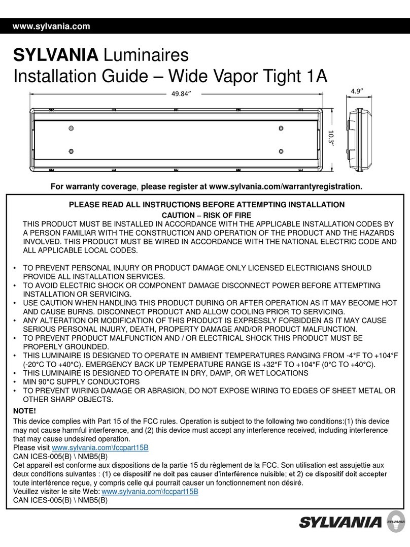
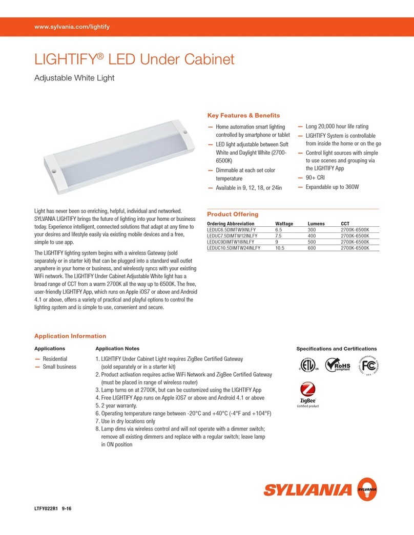
Sylvania briteline led raptor User manual

Instructions
Installation / Warranty Instructions

Page 2
PAGE 1 OF 2 COPYRIGHT GERARD LIGHTING ABN 71 115 184 999 Vi2015
Gerard Lighting Pty Ltd
96-112 Gow Street, Padstow, NSW 2211
T: 02 9794 9300 | www.gerardlighting.com.au
INSTALLATION / WARRANTY INSTRUCTIONS issue date: 01/04/2016
PRODUCT BRAND - Sylvania
PRODUCT NAME / CODES - Sylvania Briteline LED Raptor – SR4H757A2
PLEASE READ THESE INSTALLATION INSTRUCTIONS CAREFULLY BEFORE INSTALLING OR MAINTAINING THIS
EQUIPMENT. THE PRODUCT IS DESIGNED FOR INSTALLATION AND MAINTENANCE IN ACCORDANCE WITH
RELEVANT AUSTRALIAN STANDARDS (AS3000) AND LOCAL REGULATIONS (WHERE APPLICABLE), BY AN
AUTHORISED AND LICENCED ELECTRICIAN. THE INSTALLATION INSTRUCTIONS WERE CORRECT AT THE TIME OF PRINT.
TO REFLECT CHANGES IN TECHNOLOGY AND AUSTRALIAN STANDARDS; GERARD LIGHTING RESERVES THE RIGHT TO AMEND
THE INSTRUCTIONS WITHOUT NOTICE. UPDATED GUIDELINES CAN BE FOUND ON THE RELEVANT BRAND WEB SITE.
IMPORTANT - THE PRODUCT MUST BE MAINTAINED AND OPERATED IN ACCORDANCE WITH THE MANUFACTURER’S
INSTRUCTIONS, FAILURE TO DO SO MAY DAMAGE THE PRODUCT AND SERVICES. IT IS STRONGLY RECOMMENDED THAT THIS
IMPORTANT NOTE BE COMMUNICATED TO THE OWNER AND OR OPERATOR OF THE INSTALLATION AT THE TIME OF SITE
COMMISSIONING. GOOD PRACTICE DOES NOT RECOMMEND THE 24/7 USE OF PRODUCTS WITHOUT THE APPLICATION OF
SUITABLE SWITCH CYCLE INTERVALS. FURTHERMORE, WITH THE OMISSION OF NOMINATED SURVIVAL CURVES AND OR
RECOMMENDED OPERATING HOURS, PRODUCT DESIGN EXPECTATIONS PROVIDE FOR A CONTINUAL DAILY USAGE OF 6 HOURS
FOR RESIDENTIAL APPLICATIONS AND A CONTINUAL DAILY USAGE OF 12 HOURS FOR COMMERCIAL AND INDUSTRIAL
APPLICATIONS. ALL PRODUCTS MUST BE THOROUGHLY CLEANED ON A REGULAR BASIS AT INTERVALS THAT REFLECT IN THE
INSTALLATION ENVIRONMENT, ENSURING THE OPTICAL PERFORMANCE, TOGETHER WITH THE ELECTRICAL, MECHANICAL AND
STRUCTURAL INTEGRITY AS DESIGNED, IS MAINTAINED THROUGHOUT THE SERVICE LIFE OF THE PRODUCT.
For the latest product online reference data,
simply install and activate a QR code
scanner application on your smartphone.
For more information refer brand web.
1. PRODUCT SPECIFICATION: 240V System 415V System
Product brand - Sylvania -Sylvania
Type of Protection - Class I - Class I
IP Rating - for interior products, the IP rating nominated
is “from below the ceiling” unless specifically nominated. - IP66 - IP66
Nominal design Voltage - 240V - 415V
Circuit wattage - 1260W - 1260W
Line current - 5.5A, - 3.2A
Important – when installing electronic or HID lighting equipment, the installer must consider the In-rush start current (if any) as
documented on the control gear identification label when selecting appropriate circuit controls or protective devices.
Power factor - 0.9 -0.9
Nominal Freq. (Hz) - 50 Hz -050Hz
Rated Minimum / Maximum Ambient Temperature - -10°C / 40°C - -10°C / 40°C
Suitable for direct mounting on flammable surfaces - NO - NO
Dimmable (if relevant refer brand web for approved list) - YES 0-10V Analogue - YES 0-10V Analogue
Installation orientation - -10 deg to +60 deg on the horizontal
Designed application - Exterior use, Insterior on GL approval
Rated average design life - 36000hrs @ L90
2. APPROVALS: The RCM marking of this product applies to AS/NZS CISPR15 (EMC) “Limits and methods of
measurement of radio disturbance characteristics of electrical lighting and similar equipment”. This
product is designed to conform to AS/NZS60598 “Luminaires, general requirements and tests”.
3. STORAGE: Prior to installation products are to be stored in cool and dry conditions.
4. APPLICATION: The installation application and orientation of the product is designed in accordance with the nominated
product IP rating, class designation and these installation instructions. Installation environments and operating conditions
beyond these instructions are not recommended.
5. INSTALLATION / GENERAL: Installation of the product is to be completed by an authorized and licensed electrician, in
accordance with these instructions, relevant Australia standards and local regulations (where applicable). Termination of product
wiring, together with the installation of the product must be in a manner and orientation that maintains the integrity of the
designated IP rating of the product For electronic control equipment (when supplied) DO NOT MEGGER between A and N.
QR CODE
PLACEMENT
IF AVAILABLE
PAGE 1 OF 2 COPYRIGHT GERARD LIGHTING ABN 71 115 184 999 Vi2015
Gerard Lighting Pty Ltd
96-112 Gow Street, Padstow, NSW 2211
T: 02 9794 9300 | www.gerardlighting.com.au
INSTALLATION / WARRANTY INSTRUCTIONS issue date: 01/04/2016
PRODUCT BRAND - Sylvania
PRODUCT NAME / CODES - Sylvania Briteline LED Raptor – SR4H757A2
PLEASE READ THESE INSTALLATION INSTRUCTIONS CAREFULLY BEFORE INSTALLING OR MAINTAINING THIS
EQUIPMENT. THE PRODUCT IS DESIGNED FOR INSTALLATION AND MAINTENANCE IN ACCORDANCE WITH
RELEVANT AUSTRALIAN STANDARDS (AS3000) AND LOCAL REGULATIONS (WHERE APPLICABLE), BY AN
AUTHORISED AND LICENCED ELECTRICIAN. THE INSTALLATION INSTRUCTIONS WERE CORRECT AT THE TIME OF PRINT.
TO REFLECT CHANGES IN TECHNOLOGY AND AUSTRALIAN STANDARDS; GERARD LIGHTING RESERVES THE RIGHT TO AMEND
THE INSTRUCTIONS WITHOUT NOTICE. UPDATED GUIDELINES CAN BE FOUND ON THE RELEVANT BRAND WEB SITE.
IMPORTANT - THE PRODUCT MUST BE MAINTAINED AND OPERATED IN ACCORDANCE WITH THE MANUFACTURER’S
INSTRUCTIONS, FAILURE TO DO SO MAY DAMAGE THE PRODUCT AND SERVICES. IT IS STRONGLY RECOMMENDED THAT THIS
IMPORTANT NOTE BE COMMUNICATED TO THE OWNER AND OR OPERATOR OF THE INSTALLATION AT THE TIME OF SITE
COMMISSIONING. GOOD PRACTICE DOES NOT RECOMMEND THE 24/7 USE OF PRODUCTS WITHOUT THE APPLICATION OF
SUITABLE SWITCH CYCLE INTERVALS. FURTHERMORE, WITH THE OMISSION OF NOMINATED SURVIVAL CURVES AND OR
RECOMMENDED OPERATING HOURS, PRODUCT DESIGN EXPECTATIONS PROVIDE FOR A CONTINUAL DAILY USAGE OF 6 HOURS
FOR RESIDENTIAL APPLICATIONS AND A CONTINUAL DAILY USAGE OF 12 HOURS FOR COMMERCIAL AND INDUSTRIAL
APPLICATIONS. ALL PRODUCTS MUST BE THOROUGHLY CLEANED ON A REGULAR BASIS AT INTERVALS THAT REFLECT IN THE
INSTALLATION ENVIRONMENT, ENSURING THE OPTICAL PERFORMANCE, TOGETHER WITH THE ELECTRICAL, MECHANICAL AND
STRUCTURAL INTEGRITY AS DESIGNED, IS MAINTAINED THROUGHOUT THE SERVICE LIFE OF THE PRODUCT.
1. PRODUCT SPECIFICATION: Luminaire head only – Control gear refer additional instruction manual
Product brand - Sylvania
Product weight - 28.6Kgs
Type of Protection - Class I
IP Rating - for interior products, the IP rating nominated
is “from below the ceiling” unless specifically nominated. - IP66
Important – when installing electronic or HID lighting equipment, the installer must consider the In-rush start current (if any) as
documented on the control gear identification label when selecting appropriate circuit controls or protective devices.
Voltage - 130 – 150V DC per channel
Current - 2.1 - 2.2A per channel
Rated Minimum / Maximum Ambient Temperature - 0°C / 40°C
Suitable for direct mounting on flammable surfaces - NO
Dimmable - Refer compatible control gear
Installation orientation - -10 deg to +60 deg on the horizontal refer page 5
Designed application - Exterior use only: Refer Section 6A
Rated average design life - 36000hrs @ L90
Minimum distance from lit objects - 5m
2. APPROVALS: The RCM marking of this product applies to AS/NZS CISPR15 (EMC) “Limits and methods of
measurement of radio disturbance characteristics of electrical lighting and similar equipment”. This
product is designed to conform to AS/NZS60598.1:2013 “Luminaires, general requirements and tests”,
AS/NZS60598.2.5:2002“Luminaires - Particular requirements – Floodlights”
3. STORAGE: Prior to installation products are to be stored in cool and dry conditions.
4. APPLICATION: The installation application and orientation of the product is designed in accordance with the nominated
product IP rating, class designation and these installation instructions. Installation environments and operating conditions
beyond these instructions are not recommended.
5. INSTALLATION / GENERAL:Installation of the product is to be completed by an authorized and licensed electrician, in
accordance with these instructions, relevant Australia standards and local regulations (where applicable). Termination of product
wiring, together with the installation of the product must be in a manner and orientation that maintains the integrity of the
designated IP rating of the product For electronic control equipment (when supplied) DO NOT MEGGER between A and N.
6. INSTALLATION / SPECIAL CONDITIONS (relevant only for products approved for such an installation):
(a) products installed in high wind environments must have suitable installation / fastening methods applied to ensure the
product’s mounting points are not damaged through, corrosion, constant vibration and or movement. Exterior products are
designed with precise vertical aiming limits, which should not be exceeded.Any vertical floodlight aiming requirements should

Page 3
Gerard Lighting Pty Ltd
96 - 112 Gow Street, Padstow, NSW 2211
Tel: 02 9794 930
www.gerardlighting.com.au
PAGE 2 OF 2 COPYRIGHT GERARD LIGHTING ABN 71 115 184 999 Vi2015
Gerard Lighting Pty Ltd
96-112 Gow Street, Padstow, NSW 2211
T: 02 9794 9300 | www.gerardlighting.com.au
be specifically validated in writing with the relevant brand before consideration. Product has been tested and compliant to
AS/NZS60598.2.5:2002 Region C, Terrain Category 2 Wind Loading, for wind speeds up to 250Km/H at a mounting height of
20m, after such an occurrence the luminaire may require re aiming to original lighting design. For areas outside of this scope,
requirements should be specifically validated in writing with the relevant brand before consideration
For luminaires located in Wind Region A and mounted as per table below, no re aiming will be required.
Wind Region A
Table above measured to AS/NZS1170.2:2011”Structural Design Actions – Wind Actions”
(b) products installed in corrosive or salt laden environments require special consideration and such; specific product
selection, inclusive of suitable fastening methods and extensive ongoing maintenance of products installed in these environments
require professional advice. It is essential that all aspects of the product selection, material specification and maintenance are
specifically designed for such use and a cleaning program be adopted that maintains the design integrity of the product.
7. MAINTENANCE:
(a) The supply must be isolated before opening or accessing the luminaire. Product maintenance is IMPORTANT and is critical to
the products designed performance. The product is to be maintained in accordance with the manufacturer’s instructions. For the
latest product maintenance guides please go to relevant brand web site. Gerard Lighting is not responsible for any product not
maintained in accordance with the recommended procedure or intervals. (b) lamps (where provided): The product is
designed with the supplied (LEDs) / LAMP/s and it is strongly recommended that any LAMP / (LEDs) changes (if any) be made in
accordance with the type, colour and brand supplied. For recommended LAMP / LED maintenance or operating guides (inclusive
of recommended product switch cycles and mandatory run-in procedures for HID and Fluorescent lamps when used with
dimming circuits), Gerard Lighting recommends the application of the lamp manufacturer’s operating guidelines, which can be
found on manufacturer’s website. Gerard Lighting is not responsible for the product performance of alternative lamp/s used. As a
member of FluroCycle, we encourage recycling of lamps and components. (c) Luminaire must be kept clear of foreign matter –
buildup of debris will degrade performance and void warranty. (d) Do not use high pressure cleaners. To maintain peak
optical performance, glass shall be wiped down with a damp cloth. Do not use any abrasives or chemicals. (e) for products
supplied with glass visors or covers, do not operate the product with a damaged visor or cover; it is recommended the
product be turned off, area surrounding the product vacated and the damaged glass replaced by a professional installer
immediately.
8. WARRANTY INSTRUCTIONS: For the purpose of warranty claims (if any) the following instructions apply:
Warranty components – THE PRODUCT, (identified as the SR4H757A2 only). Warranty period - The above components are
provided with a warranty of FIVE (5) year/s or 20,000 hours of operation (which ever arrives first) against manufacturing defects
or failure to perform to specifications for products installed by an authorised installer in accordance with the manufacturer’s
installation instructions and which have not been subject to incorrect operation or maintenance, unauthorised modification or
damage arising from any intervening cause. Warranty reference - The warranty reference date commences from the date of
purchase. Warranty point of contact – Gerard Lighting Pty Ltd, 96 Gow Street Padstow NSW 2211,
phone T 02 9794 9300 contact – Gerard Lighting After Sales Support.
Warranty claim procedure – For the purpose of making a claim the customer must:
1. Contact the “point of contact” above and upon provision of proof of purchase the customer will receive a goods return advice
(GRA) number. 2. At the customer’s expense, collect and return the goods to the “point of contact” with the issued GRA number.
3. Upon receipt of the goods, Gerard Lighting will review the claim and if found to be accepted, Gerard Lighting will return a
replacement product to the customer to install at the customer’s expense. Alternatively if the claim is rejected, the customer
may request the return of the goods at their expense. Consumer Contracts - The benefits to the customer given by the Gerard
Lighting warranty are in addition to other rights and remedies of the customer if the goods are the subject of a Consumer
Contract under the Australian Consumer Law. In that event the following statement is required to be brought to the Consumer’s
attention:- Our goods come with guarantees that cannot be excluded under the Australian Consumer Law. You are entitled to a
replacement or refund for a major failure and for compensation for any other reasonably foreseeable loss or damage. You are
also entitled to have the goods repaired or replaced if the goods fail to be of acceptable quality and the failure does not amount
to a major failure. Limitation of Liability – if the goods are not purchased by the customer under a Consumer Contract within
the Australian Consumer Law then but not otherwise;- (a) the Company is not liable in tort for any loss or damage suffered by
the customer or by any third party; and (b) in no circumstances is Gerard Lighting liable to the customer or to any third party
for any loss of profits, loss of anticipated savings, economic loss or interruption of business or for any indirect or
consequential
loss
(Consequential Loss). Terms of Sale – these Warranty provisions are in substitution for any inconsistent provisions in the
Gerard Lighting Terms and Conditions of Sale in so far as they apply to the Warranty components.

Page 4
Carton Weight 34kgsRemove from carton
Lifting point indicated

Page 5
200
100
22
546
242
71
880
Gerard Lighting Pty Ltd
96 - 112 Gow Street, Padstow, NSW 2211
Tel: 02 9794 930
www.gerardlighting.com.au
60° MAX.
10° MAX
Fixture Dimensions
22
100
200
For mounting use 2 x M16 Hex Bolts
or 1 x M20 Hex Bolts

Page 6
60¡ MAX.
10¡ MAX
1603
838
Aiming Point
19mm
Aiming Point
Torque to 110Nm
Torque to 10Nm
Hex Key
23º MAX.

Page 7
Gerard Lighting Pty Ltd
96 - 112 Gow Street, Padstow, NSW 2211
Tel: 02 9794 930
www.gerardlighting.com.au
M3
Module Identication
Junction Box
Junction Box Access Cover Access
M4
M1
M2

Page 8
Aiming
There are 2 ways to set the correct aiming. When mounted on poles, it is recommend that for
best accuracy the aiming is done after the poles and floodlights have been erected and have
been allowed to settle into their installed position.
Method 1 – with inclinometer
1. Place markers, (visible from floodlight), at reference points according to lighting design.
2. To set the horizontal rotation (azimuth, this is generally set first):
a. Slightly loosen/tighten the torque on the trunnion bracket bolt so the floodlight can be
rotated while the weight is still held securely.
b. Unclip the plastic bolt head caps from the two side adjustment bolts (if necessary).
Slightly loosen/tighten the torque on the side bolts (19mm) so the floodlight can be
tilted while the weight is still held securely.
c. Rotate in azimuth, and tilt up/down the elevation of the floodlight to enable the
sighting of the appropriate marker through one of the v-notch and post sights provided
at various locations on the housing (Fig 1). Other straight sides/edges/heat sinks can
also be used to line up the marker.
Fig 1

Page 9
Gerard Lighting Pty Ltd
96 - 112 Gow Street, Padstow, NSW 2211
Tel: 02 9794 930
www.gerardlighting.com.au
d. Tighten the trunnion bracket mounting bolt to the required torque (by others) so that
floodlight will no longer rotate.
e. The azimuth angle can be marked for future reference by marking a line in the cross
arm along the back and/or front of the trunnion bracket foot (without damaging
galvanising).
3. To set the tilt angle (elevation):
a. The tilt is adjusted using the front glass as a reference plane. Attach an accurate
inclinometer to indicate tilt of the glass according the lighting design.Avoid the
irregular edges of the modules. Note, when the glass is horizontal, the built-in protractor
will indicate zero.
b. Tighten side bolts (19mm) so that the floodlight will no longer tilt (110 nm).
c. Tighten the safety side screws (5mm Hex - 10 nm).
d. The tilt angle can be marked for future reference by writing in the box provided on the
type label near the side bolt.
e. Clip on the plastic bolt covers.
Note regarding the built-in protractor:
This actually indicates the angle of the glass with respect to the trunnion bracket, and not
necessarily the true horizontal. Its reading relies on the levelness of its mounting surface being
truly horizontal for the actual tilt of the floodlight to be correctly indicated. It is for this reason
that it is not recommended that the built-in protractor is used for accurate aiming. It is for
approximate aiming only.
Note regarding a lighting design with an asymmetric optic:
The lighting design will normally list the tilt angle of the floodlight with respect to the downward
vertical (nadir). Depending on the format of the photometric data used, the design can
present the tilt angle is one of two ways:
1. The tilt of the glass, where a typical design would have tilts of 0-10 degrees (Fig. 2), or
2. The tilt of the peak intensity (or similar reference direction), where a typical design would
have tilts of 60-70 degrees (Fig. 3).
The latter type is generally preferred as the aiming arrow (vector), and thus the aiming points
used by the design will correspond to where the peak intensity is directed. Where a reference
direction angle is used, it is necessary know the difference between this angle and the nadir
(B°, see Fig 3). This should be noted in the design schedules, and it can be different for each
beam type, e.g. NB/60°.

Page 10
For example, a Raptor using an asymmetric Narrow Beam A2 reflector type (with a B=60°
offset) that requires a tilt of 660should have the glass tilted 66-60=6°. Tilts can be negative.
Method 2 – with aiming device
1. Place markers, (visible from floodlight), at reference points according to lighting design.
2. Slightly loosen/tighten the torque on the trunnion bracket bolt so the floodlight can be
rotated while the weight is still held securely.
3. Unclip the plastic bolt head caps from the two side adjustment bolts (if necessary). Slightly
loosen/tighten the torque on the side bolts (19mm) so the floodlight can be tilted while the
weight is still held securely.
4. Loosen either one of the side bolts by a few turns sufficiently to remove the blank ring, and
attach the supplied aiming sight (Fig 4). The aiming sight has a reference mark, and teeth at
5° spacing. It needs to be inserted so the mark aligns with the reference direction angle A°
(where A=90-B, Fig 2). For example, a Raptor using an asymmetric Narrow Beam A2 reflector
type (with a B=60° offset), A=90-60=30° (Fig 5). For a symmetric reflector angle B will be 0° so
that angle A=90°.
5. Re-tighten the torque on the side bolt so the floodlight can be tilted while the weight is still
held securely.
6. Using the v-notch and post sight on the aiming device aim to the applicable marker (Fig 4).
The sight ring can be left in place.
7. Tighten the trunnion bracket mounting bolt to the required torque (by others) so that
floodlight will no longer rotate.
8. The azimuth angle can be marked for future reference by marking a line in the cross arm
along the back and/or front of the trunnion bracket foot (without damaging galvanising).
9. Tighten side bolts (19mm) so that the floodlight will no longer tilt (110 nm).
10. Tighten the safety side screws (5mm Hex - 10 nm).
11. The tilt angle can be marked for future reference by writing in the box provided on the type
label near the side bolt.
12. Clip on the plastic bolt covers.
Fig 2
Fig 3

Page 11Copyright Gerard Lighting ABN: 71 115 184 999 Vi2015
Gerard Lighting Pty Ltd
96 - 112 Gow Street, Padstow, NSW 2211
Tel: 02 9794 930
www.gerardlighting.com.au
Note, an optional optical sight can be attached to the supplied sighting ring for longer throws
(Fig 6).
Fig 4
Fig 5
Fig 6
Put marker at
30deg
Cable must be secured
to trunnion after aiming
100mm MIN.
Fig 5
Aiming Point

Sylvania is a brand of Gerard Lighting Pty Ltd
Table of contents
Other Sylvania Light Fixture manuals
Popular Light Fixture manuals by other brands

Mark
Mark MBAR 381 IP user manual

HAMPTON BAY
HAMPTON BAY HD41247 Use and care guide

Lightmybricks
Lightmybricks LEGO Land Rover Defender 42110 manual

afx light
afx light HYBRID-470LED-FC user manual

superbrightleds
superbrightleds STN-1-TW user manual

Sunsystem
Sunsystem RS 1850 LED Installation and operating instructions