Luminaires SYLVANIA
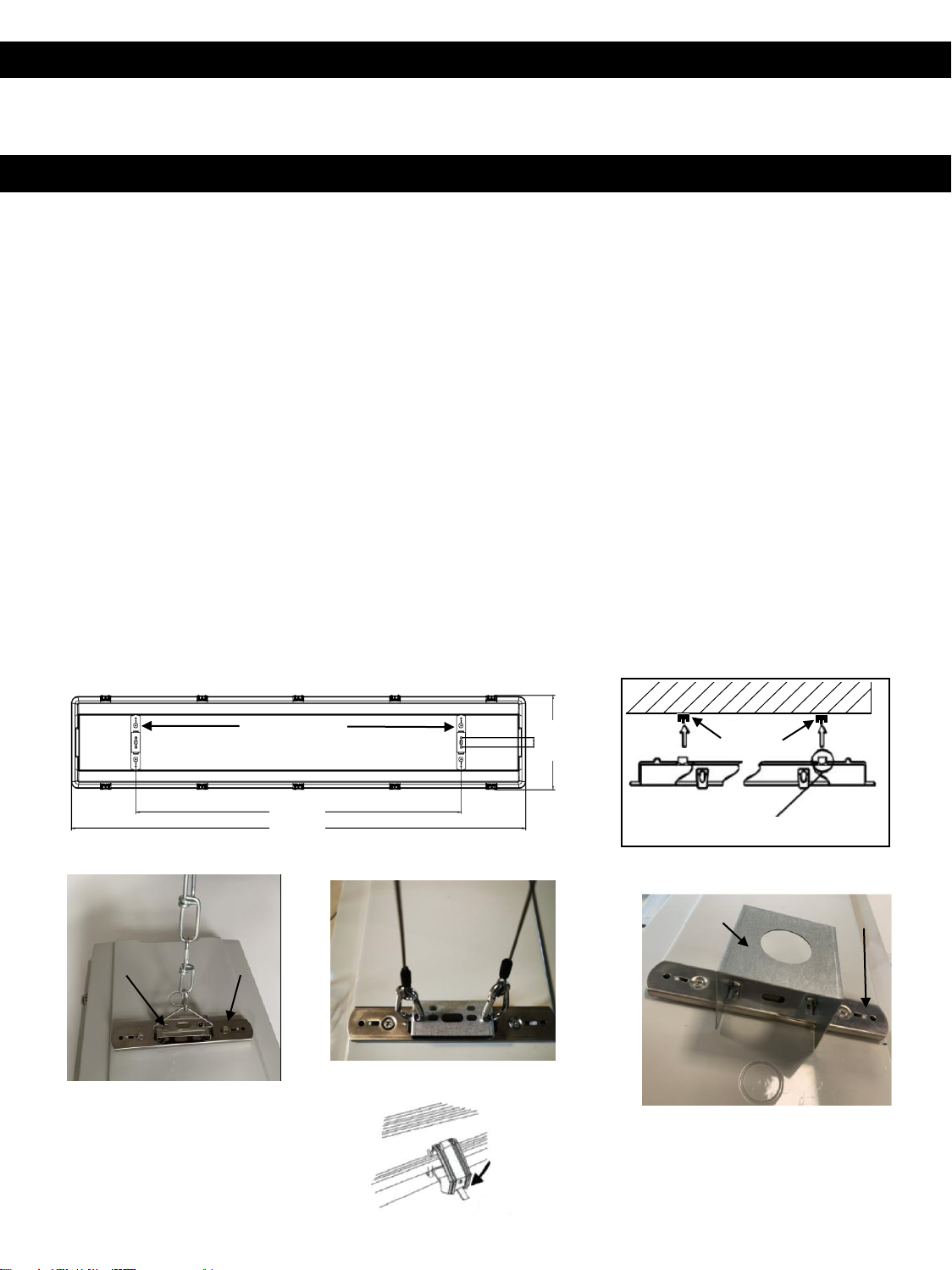
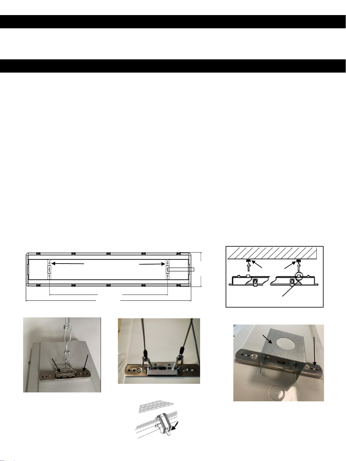
Guide d’installation – Luminaire étanche à la vapeur large 1A
www.sylvania.com
Pour la garantie, veuillez-vous enregistrer à www.sylvania.com/warrantyregistration.
VEUILLEZ LIRE TOUTES LES DIRECTIVES AVANT DE DÉBUTER L’INSTALLATION
ATTENTION – RISQUE D’INCENDIE
CE PRODUIT DOIT ÊTRE INSTALLÉ EN RESPECTANT LES EXIGENCES DES CODES D’INSTALLATION
APPLICABLES PAR UNE PERSONNE FAMILIÈRE AVEC LA CONSTRUCTION ET L’OPÉRATION DU PRODUIT AINSI
QUE DES DANGERS INHÉRENTS. CE PRODUIT DOIT ÊTRE CONNECTÉ EN RESPECTANT LES EXIGENCES DU
CODE DE L’ÉLECTRICITÉ NATIONAL ET DE TOUS LES CODES LOCAUX APPLICABLES.
•AFIN DE PRÉVENIR LES BLESSURES CORPORELLES OU DES DOMMAGES AU PRODUIT, SEULS LES
ÉLECTRICIENS LICENCIÉS DEVRAIENT EFFECTUER L’INSTALLATION
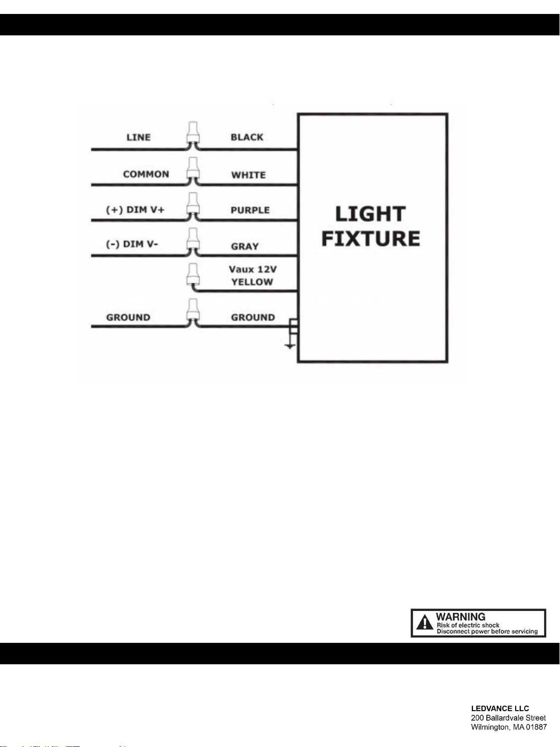
• AFIN D’ÉVITER LES CHOCS ÉLECTRIQUES OU D’ENDOMMAGER LES COMPOSANTS, DÉBRANCHER
L’ALIMENTATION AVANT D’EFFECTUER L’INSTALLATION OU L’ENTRETIEN
•FAITES PREUVE DE PRUDENCE LORSQUE VOUS MANIPULEZ CE PRODUIT PENDANT SON OPÉRATION OU
IMMÉDIATEMENT APRÈS PUISQU’IL PEUT DEVENIR CHAUD ET CAUSER DES BRÛLURES. DÉBRANCHER LE
PRODUIT ET LE LAISSER REFROIDIR AVANT D’EFFECTEUR L’ENTRETIEN.
• TOUT CHANGEMENT OU MODIFICATION APPORTÉ À CE PRODUIT EST EXPRESSÉMENT DÉFENDU PUISQU’IL
PEUT CAUSER DES BLESSURES CORPORELLES, UN DÉCÈS, DES DOMMAGES À LA PROPRIÉTÉ ET OU UN
MAUVAIS FONCTIONNEMENT DU PRODUIT
•POUR PRÉVENIR UN MAUVAIS FONCTIONNEMENT DU PRODUIT ET/OU UN CHOC ÉLECTRIQUE, CE PRODUIT
DOIT OFFRIR UNE MISE À LA TERRE ADÉQUATE
•CE LUMINAIRE EST CONÇU POUR FONCTIONNER À DES TEMPÉRATURES AMBIANTES ENTRE -20°C À
•40°C (-4°F À +104°F). LA TEMPÉRATURE AMBIANTE POUR LA BATTERIE DE SECOUR EST DE 0C À 40C (32°F À
+104°F)
• CE LUMINAIRE CONVIENT À L’UTILISATION DANS LES ENDROITS SEC, HUMIDE OU MOUILLÉ
• CONDUCTEURS D’ALIMENTATION DE 90°C MINIMUM
• AFIN DE PRÉVENIR LES DOMMAGES OU L’ABRASION DU CÂBLAGE, NE PAS EXPOSER LE CÂBLAGE À DES
BORDURES DE FEUILLE DE MÉTAL OU AUTRES OBJETS TRANCHANTS
NOTE!
This device complies with Part 15 of the FCC rules. Operation is subject to the following two conditions:(1) this device may not cause
harmful interference, and (2) this device must accept any interference received, including interference that may cause undesired
operation. Please visit www.sylvania.com\fccpart15B
CAN ICES-005(B) \ NMB5(B)
Cet appareil est conforme aux dispositions de la partie 15 du règlement de la FCC. Son utilisation est assujettie aux deux conditions
suivantes : (1) ce dispositif ne doit pas causer d’interférence nuisible; et 2) ce dispositif doit accepter toute interférence reçue,
y compris celle qui pourrait causer un fonctionnement non désiré.
Veuillez visiter le site Web: www.sylvania.com\fccpart15B
CAN ICES-005(B) \ NMB5(B)
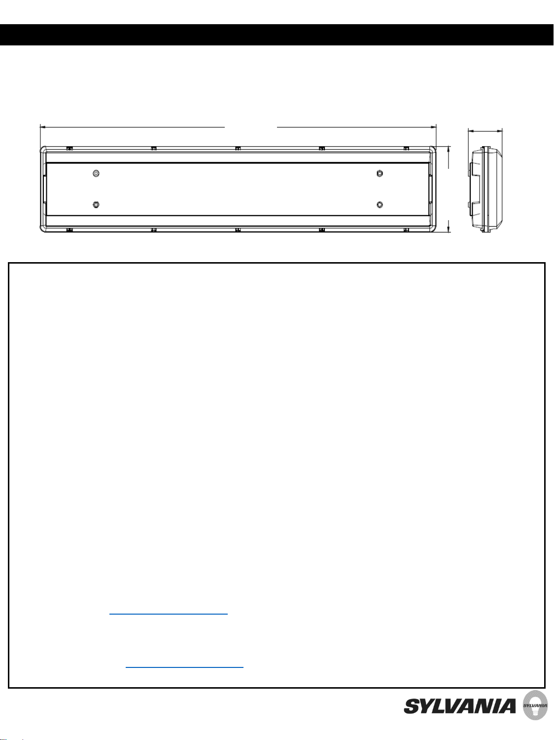
49,84 po 4,9 po
10,3 po